UN65U Users ManualEnglish
Page 2
SPECIFICATIONS AND INFORMATION CONTAINED IN THIS MANUAL ARE FURNISHED FOR INFORMATIONAL USE ONLY, AND ARE SUBJECT TO CHANGE AT ANY TIME WITHOUT NOTICE, AND SHOULD NOT BE CONSTRUED AS A COMMITMENT BY ASUS. ASUS ASSUMES NO RESPONSIBILITY OR LIABILITY FOR ANY ERRORS OR INACCURACIES THAT MAY APPEAR IN THIS MANUAL, INCLUDING THE PRODUCTS AND SOFTWARE... SERVICE AND SUPPORT Visit our multi-language web site at https://www.asus.com/support Copyright © 2016 ASUSTeK COMPUTER INC. E12068 First Edition October 2016 COPYRIGHT INFORMATION No part of this manual, including the products and software ...
SPECIFICATIONS AND INFORMATION CONTAINED IN THIS MANUAL ARE FURNISHED FOR INFORMATIONAL USE ONLY, AND ARE SUBJECT TO CHANGE AT ANY TIME WITHOUT NOTICE, AND SHOULD NOT BE CONSTRUED AS A COMMITMENT BY ASUS. ASUS ASSUMES NO RESPONSIBILITY OR LIABILITY FOR ANY ERRORS OR INACCURACIES THAT MAY APPEAR IN THIS MANUAL, INCLUDING THE PRODUCTS AND SOFTWARE... SERVICE AND SUPPORT Visit our multi-language web site at https://www.asus.com/support Copyright © 2016 ASUSTeK COMPUTER INC. E12068 First Edition October 2016 COPYRIGHT INFORMATION No part of this manual, including the products and software ...
UN65U Users ManualEnglish
Page 3
... your VivoMini Features...8 Front panel...8 Left panel...9 Right panel...9 Rear panel...10 Using your VivoMini Getting started 14 Connecting the AC power adapter 14 Connecting a display panel 16 Connecting USB keyboard or mouse 17 Turning on your VivoMini 17 Turning off your VivoMini 18 Putting your VivoMini to sleep 18 Entering the BIOS Setup 18 Quickly enter the BIOS 18 Memory upgrade Upgrading memory modules 20 Appendix Safety information 28 Setting up your system 28 Care during use 28 Regulatory notices 30 ASUS contact information 36 VivoMini UN Series 3
... your VivoMini Features...8 Front panel...8 Left panel...9 Right panel...9 Rear panel...10 Using your VivoMini Getting started 14 Connecting the AC power adapter 14 Connecting a display panel 16 Connecting USB keyboard or mouse 17 Turning on your VivoMini 17 Turning off your VivoMini 18 Putting your VivoMini to sleep 18 Entering the BIOS Setup 18 Quickly enter the BIOS 18 Memory upgrade Upgrading memory modules 20 Appendix Safety information 28 Setting up your system 28 Care during use 28 Regulatory notices 30 ASUS contact information 36 VivoMini UN Series 3
UN65U Users ManualEnglish
Page 4
... damage to complete a task. Conventions used in this manual To highlight key information in this manual. 4 VivoMini UN Series This indicates sections that can refer to select. NOTE: This message contains additional information and tips that you with information on how to install new memory modules to know your VivoMini This chapter details the hardware components of your PC, organized through...
... damage to complete a task. Conventions used in this manual To highlight key information in this manual. 4 VivoMini UN Series This indicates sections that can refer to select. NOTE: This message contains additional information and tips that you with information on how to install new memory modules to know your VivoMini This chapter details the hardware components of your PC, organized through...
UN65U Users ManualEnglish
Page 5
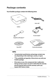
VivoMini UN Series 5 Package contents Your VivoMini package contains the following items: VivoMini DisplayPort to VGA adapter** Power cable* AC power adapter* Driver DVD** Technical documentations NOTE: • *Actual product specifications and package contents may vary depending on the model type, country, or region. • **The availability and quantity of these items vary with your VivoMini package. • If the device or any of its components fail or malfunction...
VivoMini UN Series 5 Package contents Your VivoMini package contains the following items: VivoMini DisplayPort to VGA adapter** Power cable* AC power adapter* Driver DVD** Technical documentations NOTE: • *Actual product specifications and package contents may vary depending on the model type, country, or region. • **The availability and quantity of these items vary with your VivoMini package. • If the device or any of its components fail or malfunction...
UN65U Users ManualEnglish
Page 8
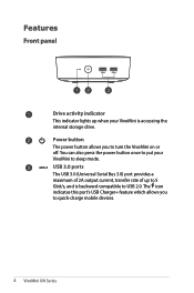
You can also press the power button once to put your VivoMini is backward compatible to USB 2.0. Power button The power button allows you to turn the VivoMini on or off. Features Front panel Drive activity indicator This indicator lights up to 5 Gbit/s, and is accessing the internal storage drive. The icon indicates this port's USB Charger+ feature which allows you to quick-charge mobile devices. 8 VivoMini UN Series USB 3.0 ports The USB 3.0 (Universal Serial Bus 3.0) port provides a maximum of 2A output current, transfer rate of up when your VivoMini to sleep mode.
You can also press the power button once to put your VivoMini is backward compatible to USB 2.0. Power button The power button allows you to turn the VivoMini on or off. Features Front panel Drive activity indicator This indicator lights up to 5 Gbit/s, and is accessing the internal storage drive. The icon indicates this port's USB Charger+ feature which allows you to quick-charge mobile devices. 8 VivoMini UN Series USB 3.0 ports The USB 3.0 (Universal Serial Bus 3.0) port provides a maximum of 2A output current, transfer rate of up when your VivoMini to sleep mode.
UN65U Users ManualEnglish
Page 9
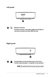
VivoMini UN Series 9 NOTE: The position for this slot may vary per model. Right panel The Kensington security slot allows you to secure your VivoMini to read and write data to and from MMC/SD cards. Left panel Memory card slot The built-in memory card reader enables your VivoMini using Kensington® compatible security products.
VivoMini UN Series 9 NOTE: The position for this slot may vary per model. Right panel The Kensington security slot allows you to secure your VivoMini to read and write data to and from MMC/SD cards. Left panel Memory card slot The built-in memory card reader enables your VivoMini using Kensington® compatible security products.
UN65U Users ManualEnglish
Page 10
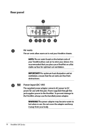
... are free from your VivoMini on the bottom side of your VivoMini allow warm air to exit your device. IMPORTANT! WARNING! For optimum heat dissipation and air ventilation, ensure that you place your body. 10 VivoMini UN Series Do not cover the adapter and keep it away from obstructions. To prevent damage to the VivoMini. Power supplied through this jack. Rear panel Air...
... are free from your VivoMini on the bottom side of your VivoMini allow warm air to exit your device. IMPORTANT! WARNING! For optimum heat dissipation and air ventilation, ensure that you place your body. 10 VivoMini UN Series Do not cover the adapter and keep it away from obstructions. To prevent damage to the VivoMini. Power supplied through this jack. Rear panel Air...
UN65U Users ManualEnglish
Page 11
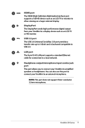
... external display. HDMI port The HDMI (High Definition Multimedia Interface) port supports a Full-HD device such as an LCD TV or HD monitor. LAN port The 8-pin RJ-45 LAN port supports a standard Ethernet cable for connection to USB 2.0. Headphone output/microphone input combo jack port This port allows you to connect your VivoMini to amplified speakers or headphones. NOTE: This port does not support three-conductor 3.5mm microphone. VivoMini UN Series 11 You can also use this port to connect...
... external display. HDMI port The HDMI (High Definition Multimedia Interface) port supports a Full-HD device such as an LCD TV or HD monitor. LAN port The 8-pin RJ-45 LAN port supports a standard Ethernet cable for connection to USB 2.0. Headphone output/microphone input combo jack port This port allows you to connect your VivoMini to amplified speakers or headphones. NOTE: This port does not support three-conductor 3.5mm microphone. VivoMini UN Series 11 You can also use this port to connect...
UN65U Users ManualEnglish
Page 14
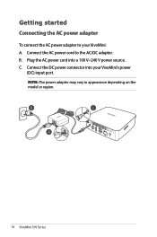
B. NOTE: The power adapter may vary in appearance depending on the model or region. 14 VivoMini UN Series Getting started Connecting the AC power adapter To connect the AC power adapter to the AC/DC adapter. Plug the AC power cord into your VivoMini: A. Connect the DC power connector into a 100 V~240 V power source. C. Connect the AC power cord to your VivoMini's power (DC) input port.
B. NOTE: The power adapter may vary in appearance depending on the model or region. 14 VivoMini UN Series Getting started Connecting the AC power adapter To connect the AC power adapter to the AC/DC adapter. Plug the AC power cord into your VivoMini: A. Connect the DC power connector into a 100 V~240 V power source. C. Connect the AC power cord to your VivoMini's power (DC) input port.
UN65U Users ManualEnglish
Page 16
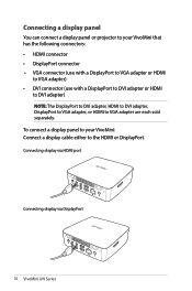
... following connectors: • HDMI connector • DisplayPort connector • VGA connector (use with a DisplayPort to VGA adapter or HDMI to VGA adapter) • DVI connector (use with a DisplayPort to DVI adapter or HDMI to DVI adapter) NOTE: The DisplayPort to DVI adapter, HDMI to DVI adapter, DisplayPort to VGA adapter, or HDMI to the HDMI or DisplayPort. Connecting display via HDMI port Connecting display via DisplayPort 16 VivoMini UN Series Connecting a display panel You can connect a display panel or projector to your VivoMini: Connect a display cable either to VGA adapter...
... following connectors: • HDMI connector • DisplayPort connector • VGA connector (use with a DisplayPort to VGA adapter or HDMI to VGA adapter) • DVI connector (use with a DisplayPort to DVI adapter or HDMI to DVI adapter) NOTE: The DisplayPort to DVI adapter, HDMI to DVI adapter, DisplayPort to VGA adapter, or HDMI to the HDMI or DisplayPort. Connecting display via HDMI port Connecting display via DisplayPort 16 VivoMini UN Series Connecting a display panel You can connect a display panel or projector to your VivoMini: Connect a display cable either to VGA adapter...
UN65U Users ManualEnglish
Page 17
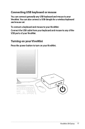
VivoMini UN Series 17 Turning on your VivoMini. To connect a keyboard and mouse to your VivoMini: Connect the USB cable from your keyboard and mouse to turn on your VivoMini Press the power button to any USB keyboard and mouse to your VivoMini. You can connect generally any of the USB ports of your VivoMini. Connecting USB keyboard or mouse You can also connect a USB dongle for a wireless keyboard and mouse set.
VivoMini UN Series 17 Turning on your VivoMini. To connect a keyboard and mouse to your VivoMini: Connect the USB cable from your keyboard and mouse to turn on your VivoMini Press the power button to any USB keyboard and mouse to your VivoMini. You can connect generally any of the USB ports of your VivoMini. Connecting USB keyboard or mouse You can also connect a USB dongle for a wireless keyboard and mouse set.
UN65U Users ManualEnglish
Page 18
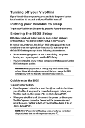
... BIOS settings or update. Turning off your VivoMini If your VivoMini is off . Inappropriate BIOS settings may result to ensure optimal performance. Reconnect the power cable and press the power button to sleep To put your VivoMini. NOTE: POST (Power-On Self Test) is a series of a trained service personnel. Entering the BIOS Setup BIOS (Basic Input and Output System) stores system hardware settings that run the BIOS Setup. • You have installed a new system component that you turn on your VivoMini...
... BIOS settings or update. Turning off your VivoMini If your VivoMini is off . Inappropriate BIOS settings may result to ensure optimal performance. Reconnect the power cable and press the power button to sleep To put your VivoMini. NOTE: POST (Power-On Self Test) is a series of a trained service personnel. Entering the BIOS Setup BIOS (Basic Input and Output System) stores system hardware settings that run the BIOS Setup. • You have installed a new system component that you turn on your VivoMini...
UN65U Users ManualEnglish
Page 20
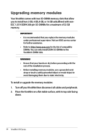
... with its top side facing down. 20 VivoMini UN Series To install or upgrade the memory modules: 1. Place the VivoMini on a flat stable surface, with nonECC 1.35 V DDR4 260-pin SO-DIMMs for the list of 32 GB memory. WARNING! • Ensure that you to the VivoMini's DIMM slots. IMPORTANT! • It is recommended that your VivoMini then disconnect all cables and peripherals. 2.
... with its top side facing down. 20 VivoMini UN Series To install or upgrade the memory modules: 1. Place the VivoMini on a flat stable surface, with nonECC 1.35 V DDR4 260-pin SO-DIMMs for the list of 32 GB memory. WARNING! • Ensure that you to the VivoMini's DIMM slots. IMPORTANT! • It is recommended that your VivoMini then disconnect all cables and peripherals. 2.
UN65U Users ManualEnglish
Page 21
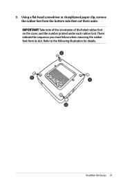
3. VivoMini UN Series 21 Using a flat-head screwdriver or straightened paper clip, remove the rubber feet from its slot. IMPORTANT! Refer to the following illustration for details. Take note of the orientation of the holed rubber foot on the cover, and the number printed under each rubber foot. These indicate the sequence you must follow when removing the rubber foot from the bottom side then set them aside.
3. VivoMini UN Series 21 Using a flat-head screwdriver or straightened paper clip, remove the rubber feet from its slot. IMPORTANT! Refer to the following illustration for details. Take note of the orientation of the holed rubber foot on the cover, and the number printed under each rubber foot. These indicate the sequence you must follow when removing the rubber foot from the bottom side then set them aside.
UN65U Users ManualEnglish
Page 28
.... • Set up the system on a stable surface. • Openings on your system • Read and follow the operating instructions. - The system performance changes. 28 VivoMini UN Series The system was dropped or the cabinet is damaged. - Do not block or cover these openings. Safety information Your VivoMini is designed and tested to meet the latest standards of the devices plugged into the...
.... • Set up the system on a stable surface. • Openings on your system • Read and follow the operating instructions. - The system performance changes. 28 VivoMini UN Series The system was dropped or the cabinet is damaged. - Do not block or cover these openings. Safety information Your VivoMini is designed and tested to meet the latest standards of the devices plugged into the...
UN65U Users ManualEnglish
Page 30
... are located. Operation is subject to http://csr.asus.com/english/Takeback.htm for a Class B digital device, pursuant to provide reasonable protection against harmful interference in a residential installation. If this equipment does cause harmful interference to radio or television reception, which can radiate radio frequency energy and, if not installed and used in accordance with manufacturer's instructions, may...
... are located. Operation is subject to http://csr.asus.com/english/Takeback.htm for a Class B digital device, pursuant to provide reasonable protection against harmful interference in a residential installation. If this equipment does cause harmful interference to radio or television reception, which can radiate radio frequency energy and, if not installed and used in accordance with manufacturer's instructions, may...
UN65U Users ManualEnglish
Page 31
... , the user is connected. • Consult the dealer or an experienced radio/TV technician for satisfying RF exposure compliance. the equipment off and on a circuit different from all persons and must not be co-located or operating in [Article 3.1b] • Testing for this transmitter must be installed to [EN 300 328-2] VivoMini UN Series 31 Any changes or...
... , the user is connected. • Consult the dealer or an experienced radio/TV technician for satisfying RF exposure compliance. the equipment off and on a circuit different from all persons and must not be co-located or operating in [Article 3.1b] • Testing for this transmitter must be installed to [EN 300 328-2] VivoMini UN Series 31 Any changes or...
UN65U Users ManualEnglish
Page 33
... to use your wireless LAN card in the Radio Interference Regulations of the Canadian Department of the device. To maintain compliance with ART for the latest information (www.art-telecom.fr) NOTE: Your WLAN Card transmits less... than 100mW, but more areas within France. This requirement is subject to the following two conditions: • This device may not cause interference and • This device must follow the specific operating instructions for satisfying RF exposure compliance. This class B digital apparatus complies with IC radiation exposure limits set...
... to use your wireless LAN card in the Radio Interference Regulations of the Canadian Department of the device. To maintain compliance with ART for the latest information (www.art-telecom.fr) NOTE: Your WLAN Card transmits less... than 100mW, but more areas within France. This requirement is subject to the following two conditions: • This device may not cause interference and • This device must follow the specific operating instructions for satisfying RF exposure compliance. This class B digital apparatus complies with IC radiation exposure limits set...
UN65U Users ManualEnglish
Page 35
...the U.S. VivoMini UN Series 35 All ASUS products with the ENERGY STAR logo comply with the ENERGY STAR standard, and the power management feature is enabled by default. NOTE: Energy Star is NOT supported on the keyboard. Environmental Protection...mouse or press any key on FreeDOS and Linux-based products. The monitor and computer are automatically set to the environment. In addition, please visit http://www.energystar.gov for detail information on the ENERGY STAR joint program. Please visit http://www.energystar.gov/powermanagement for detail information on power management...
...the U.S. VivoMini UN Series 35 All ASUS products with the ENERGY STAR logo comply with the ENERGY STAR standard, and the power management feature is enabled by default. NOTE: Energy Star is NOT supported on the keyboard. Environmental Protection...mouse or press any key on FreeDOS and Linux-based products. The monitor and computer are automatically set to the environment. In addition, please visit http://www.energystar.gov for detail information on the ENERGY STAR joint program. Please visit http://www.energystar.gov/powermanagement for detail information on power management...
UN65U Users ManualEnglish
Page 37
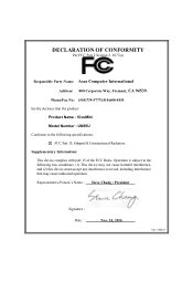
...Person's Name : Steve Chang / President Signature : Date : Nov. 24, 2016 Ver. 140331 Operation is subject to the following specifications: FCC Part 15, Subpart B, Unintentional Radiators Supplementary Information: This device complies with part 15 of the FCC ...device must accept any interference received, including interference that the product Product Name : VivoMini Model Number : UN65U Conforms to the following two conditions: (1) This device may cause undesired operation. DECLARATION OF CONFORMITY Per FCC Part 2 Section 2. 1077(a) Responsible Party Name: Asus Computer International...
...Person's Name : Steve Chang / President Signature : Date : Nov. 24, 2016 Ver. 140331 Operation is subject to the following specifications: FCC Part 15, Subpart B, Unintentional Radiators Supplementary Information: This device complies with part 15 of the FCC ...device must accept any interference received, including interference that the product Product Name : VivoMini Model Number : UN65U Conforms to the following two conditions: (1) This device may cause undesired operation. DECLARATION OF CONFORMITY Per FCC Part 2 Section 2. 1077(a) Responsible Party Name: Asus Computer International...


