
User Guide
Page 6
The use of shielded cables for connection of the monitor to the graphics card is connected. • Consult the dealer or an experienced radio/TV technician for radio noise emissions from that to which the receiver is required to Part 15 of Communications Statement This ...been tested and found to provide reasonable protection against harmful interference in the Radio Interference Regulations of the Canadian Department of the FCC Rules. Notices Federal Communications Commission Statement This device complies with manufacturerʼs instructions, may cause undesired operation. ...
The use of shielded cables for connection of the monitor to the graphics card is connected. • Consult the dealer or an experienced radio/TV technician for radio noise emissions from that to which the receiver is required to Part 15 of Communications Statement This ...been tested and found to provide reasonable protection against harmful interference in the Radio Interference Regulations of the Canadian Department of the FCC Rules. Notices Federal Communications Commission Statement This device complies with manufacturerʼs instructions, may cause undesired operation. ...
User Guide
Page 8
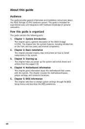
... motherboard layout, jumper settings, and connector locations. 5. About this guide is intended for experienced users and integrators with the system. How this guide Audience This guide provides general information and installation instructions about the motherboard that comes with hardware knowledge of the ASUS Vintage V2-PH2. Chapter 4: Motherboard information This chapter gives information about the ASUS Vintage V2-PH2 barebone system. Chapter 2: Basic installation This chapter provides step-by-step instructions on the front and rear panel...
... motherboard layout, jumper settings, and connector locations. 5. About this guide is intended for experienced users and integrators with the system. How this guide Audience This guide provides general information and installation instructions about the motherboard that comes with hardware knowledge of the ASUS Vintage V2-PH2. Chapter 4: Motherboard information This chapter gives information about the ASUS Vintage V2-PH2 barebone system. Chapter 2: Basic installation This chapter provides step-by-step instructions on the front and rear panel...
User Guide
Page 10
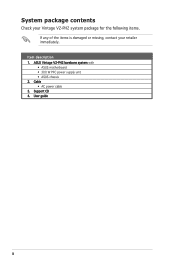
System package contents Check your Vintage V2-PH2 system package for the following items. If any of the items is damaged or missing, contact your retailer immediately. Item description 1. ASUS Vintage V2-PH2 barebone system with • ASUS motherboard • 300 W PFC power supply unit • ASUS chassis 2. Cable • AC power cable 3. Support CD 4. User guide x
System package contents Check your Vintage V2-PH2 system package for the following items. If any of the items is damaged or missing, contact your retailer immediately. Item description 1. ASUS Vintage V2-PH2 barebone system with • ASUS motherboard • 300 W PFC power supply unit • ASUS chassis 2. Cable • AC power cable 3. Support CD 4. User guide x
User Guide
Page 12
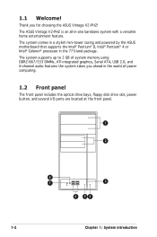
... front panel includes the optical drive bays, floppy disk drive slot, power button, and several I/O ports are located at the front panel. 1 2 8 7 3 6 54 1-2 Chapter 1: System introduction Thank you ahead in the 775-land package. The system supports up to 2 GB of system memory using DDR2-667/533 DIMMs, ATI integrated graphics, Serial ATA, USB 2.0, and 6-channel audio features the system takes you for choosing the ASUS Vintage V2-PH2! 1.1 Welcome! The ASUS Vintage V2-PH2...
... front panel includes the optical drive bays, floppy disk drive slot, power button, and several I/O ports are located at the front panel. 1 2 8 7 3 6 54 1-2 Chapter 1: System introduction Thank you ahead in the 775-land package. The system supports up to 2 GB of system memory using DDR2-667/533 DIMMs, ATI integrated graphics, Serial ATA, USB 2.0, and 6-channel audio features the system takes you for choosing the ASUS Vintage V2-PH2! 1.1 Welcome! The ASUS Vintage V2-PH2...

User Guide
Page 13
...;oppy or hard disk drives. 3. Reset button. This LED lights up when data is read from or written to turn the system on. 4. USB 2.0 ports. These slots are available for connecting USB 2.0 devices such as a mouse, printer, scanner, camera, PDA, and others. 7. This Line In (green) port connects a headphone with a stereo mini-plug. 8. Press this button to the hard disk drive. 6. Headphone port. Power button. These Universal Serial Bus 2.0 (USB 2.0) ports are for IDE optical drives. 2. 3.5-inch drive bays. ASUS Vintage V2-PH2 1-3 Two empty...
...;oppy or hard disk drives. 3. Reset button. This LED lights up when data is read from or written to turn the system on. 4. USB 2.0 ports. These slots are available for connecting USB 2.0 devices such as a mouse, printer, scanner, camera, PDA, and others. 7. This Line In (green) port connects a headphone with a stereo mini-plug. 8. Press this button to the hard disk drive. 6. Headphone port. Power button. These Universal Serial Bus 2.0 (USB 2.0) ports are for IDE optical drives. 2. 3.5-inch drive bays. ASUS Vintage V2-PH2 1-3 Two empty...

User Guide
Page 15
... Front Speaker Out Center/Bass ASUS Vintage V2-PH2 1-5 This port connects a headphone or a speaker. This port connects the tape, CD, DVD player, or other devices. 7. Chassis fan vent. Expansion slot covers. VGA port. This vent is for the PSU fan that provides ventilation inside the power supply unit. 13. Remove these covers when installing expansion cards. This 25-pin port connects a printer, scanner, or other audio sources. 12. This port allows Gigabit connection to the audio configuration table below for connecting USB 2.0 devices...
... Front Speaker Out Center/Bass ASUS Vintage V2-PH2 1-5 This port connects a headphone or a speaker. This port connects the tape, CD, DVD player, or other devices. 7. Chassis fan vent. Expansion slot covers. VGA port. This vent is for the PSU fan that provides ventilation inside the power supply unit. 13. Remove these covers when installing expansion cards. This 25-pin port connects a printer, scanner, or other audio sources. 12. This port allows Gigabit connection to the audio configuration table below for connecting USB 2.0 devices...

User Guide
Page 17
Hard disk drive bay 4. CPU socket 7. PCI slots 13. 1.4 Internal components The illustration below is the internal view of the system when you remove the top cover and the power supply unit. Proceed to Chapter 2 for your reference. Front panel cover 2. 5.25-inch optical drive bays 3. PCI Express x16 slot 11. Power supply unit 6. Chassis fan 10. DIMM sockets 8. Floppy disk drive bay 5. PCI Express x1 slot 12. The installed components are labeled for instructions on installing additional system...
Hard disk drive bay 4. CPU socket 7. PCI slots 13. 1.4 Internal components The illustration below is the internal view of the system when you remove the top cover and the power supply unit. Proceed to Chapter 2 for your reference. Front panel cover 2. 5.25-inch optical drive bays 3. PCI Express x16 slot 11. Power supply unit 6. Chassis fan 10. DIMM sockets 8. Floppy disk drive bay 5. PCI Express x1 slot 12. The installed components are labeled for instructions on installing additional system...

User Guide
Page 20
... ON Standby Power OFF Powered Off Chapter 2: Basic installation Unplug the power cable from the power outlet and make sure that you have all the components you plan to install 1. Central Processing Unit (CPU) 2. This LED lights up to avoid touching the ICs on a grounded antistatic pad or in the bag that came with an onboard standby power LED. Hard disk drive 5. Expansion card(s) 4. The motherboard comes with...
... ON Standby Power OFF Powered Off Chapter 2: Basic installation Unplug the power cable from the power outlet and make sure that you have all the components you plan to install 1. Central Processing Unit (CPU) 2. This LED lights up to avoid touching the ICs on a grounded antistatic pad or in the bag that came with an onboard standby power LED. Hard disk drive 5. Expansion card(s) 4. The motherboard comes with...

User Guide
Page 25
... and fan assembly in place, connect the CPU fan cable to the CPU heatsink or CPU before you install the heatsink and fan assembly. A B A A B 1 1 B A 3. ASUS Vintage V2-PH2 2-7 CPU_FAN CPU FAN PWM CPU FAN IN CPU FAN PWR GND ® CPU Fan Connector Do not forget to plug this connector. Hardware monitoring errors can occur if you fail to connect the CPU fan connector! If you purchased a separate CPU heatsink and fan assembly, make sure that B the four fasteners match the holes on the motherboard.
... and fan assembly in place, connect the CPU fan cable to the CPU heatsink or CPU before you install the heatsink and fan assembly. A B A A B 1 1 B A 3. ASUS Vintage V2-PH2 2-7 CPU_FAN CPU FAN PWM CPU FAN IN CPU FAN PWR GND ® CPU Fan Connector Do not forget to plug this connector. Hardware monitoring errors can occur if you fail to connect the CPU fan connector! If you purchased a separate CPU heatsink and fan assembly, make sure that B the four fasteners match the holes on the motherboard.
User Guide
Page 30
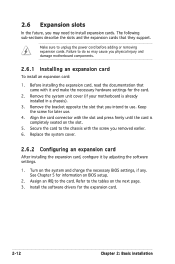
... your motherboard is completely seated on BIOS setup. 2. Before installing the expansion card, read the documentation that they support. Install the software drivers for information on the slot. 5. Turn on the next page. 3. Make sure to the tables on the system and change the necessary BIOS settings, if any. Refer to unplug the power cord before adding or removing expansion cards. Failure to do so may need to the card. Replace the system cover. 2.6.2 Configuring...
... your motherboard is completely seated on BIOS setup. 2. Before installing the expansion card, read the documentation that they support. Install the software drivers for information on the slot. 5. Turn on the next page. 3. Make sure to the tables on the system and change the necessary BIOS settings, if any. Refer to unplug the power cord before adding or removing expansion cards. Failure to do so may need to the card. Replace the system cover. 2.6.2 Configuring...

User Guide
Page 31
.../2 Compatible Mouse Port* 13 Numeric Data Processor 14 Primary IDE Channel 15 Secondary IDE Channel * These IRQs are usually available for this motherboard PCI slot 1 PCI slot 2 PCI Express x16 slot PCI Express x1 slot Onboard USB controller 1 Onboard USB controller 2 Onboard USB controller 3 Onboard USB controller 4 Onboard USB 2.0 controller Onboard IDE port Onboard HD audio Onboard LAN A B C D E F G H shared - - - - - - - - shared - - - When using PCI cards on shared slots, ensure that the drivers support "Share IRQ" or that the cards do not need IRQ assignments...
.../2 Compatible Mouse Port* 13 Numeric Data Processor 14 Primary IDE Channel 15 Secondary IDE Channel * These IRQs are usually available for this motherboard PCI slot 1 PCI slot 2 PCI Express x16 slot PCI Express x1 slot Onboard USB controller 1 Onboard USB controller 2 Onboard USB controller 3 Onboard USB controller 4 Onboard USB 2.0 controller Onboard IDE port Onboard HD audio Onboard LAN A B C D E F G H shared - - - - - - - - shared - - - When using PCI cards on shared slots, ensure that the drivers support "Share IRQ" or that the cards do not need IRQ assignments...

User Guide
Page 35
... or IDE hard disk drive. Place the chassis upright. 2. With the HDD label side up, carefully insert the drive into the 3.5-inch bay and push the drive into the bay until its screw holes align with two screws on the drive bay. 4 4 3 4. ASUS Vintage V2-PH2 2-17 Refer to this section to remove the HDD drive slot metal plate cover. 3. Use a screw driver to install additional Serial ATA or IDE hard disk drive(s).
... or IDE hard disk drive. Place the chassis upright. 2. With the HDD label side up, carefully insert the drive into the 3.5-inch bay and push the drive into the bay until its screw holes align with two screws on the drive bay. 4 4 3 4. ASUS Vintage V2-PH2 2-17 Refer to this section to remove the HDD drive slot metal plate cover. 3. Use a screw driver to install additional Serial ATA or IDE hard disk drive(s).
User Guide
Page 42
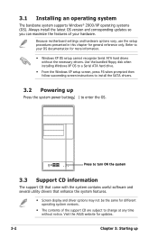
... to your hardware. Use the bundled floppy disk when installing Windows XP OS to a Serial ATA hard drive. • From the Windows XP setup screen, press F6 when prompted then follow succeeding screen instructions to install the SATA drivers. 3.2 Powering up Visit the ASUS website for general reference only. Because motherboard settings and hardware options vary, use the setup procedures presented in this chapter for updates. 3-2 Chapter 3: Starting up Press the system power button ( ) to enter the OS...
... to your hardware. Use the bundled floppy disk when installing Windows XP OS to a Serial ATA hard drive. • From the Windows XP setup screen, press F6 when prompted then follow succeeding screen instructions to install the SATA drivers. 3.2 Powering up Visit the ASUS website for general reference only. Because motherboard settings and hardware options vary, use the setup procedures presented in this chapter for updates. 3-2 Chapter 3: Starting up Press the system power button ( ) to enter the OS...

User Guide
Page 55
... system setup information such as system passwords. 4.3 Jumpers 1. Turn OFF the computer and unplug the power cord. 2. Re-install the battery. 5. The onboard button cell battery powers the RAM data in CMOS. To erase the RTC RAM: 1. Keep the cap on CLRTC jumper default position. Clear RTC RAM (CLRTC) This jumper allows you to pins 1-2. 4. Plug the power cord and turn ON the computer. 6. Removing the cap will cause system boot failure. You can clear the CMOS memory...
... system setup information such as system passwords. 4.3 Jumpers 1. Turn OFF the computer and unplug the power cord. 2. Re-install the battery. 5. The onboard button cell battery powers the RAM data in CMOS. To erase the RTC RAM: 1. Keep the cap on CLRTC jumper default position. Clear RTC RAM (CLRTC) This jumper allows you to pins 1-2. 4. Plug the power cord and turn ON the computer. 6. Removing the cap will cause system boot failure. You can clear the CMOS memory...
User Guide
Page 66
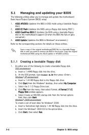
... corrupted.) 4. Click Start from the menu, then select Format. A Format 3 1/2 Floppy Disk window appears. e. c. Click Start, then select Run. 5-2 Chapter 5: BIOS setup ASUS Update (Updates the BIOS in case you to manage and update the motherboard Basic Input/Output System (BIOS) setup. 1. DOS environment a. b. Insert a formatted, high density 1.44 MB floppy disk into the drive. b. Save a copy of the following utilities allow you need to restore the BIOS in the future. Windows® XP environment...
... corrupted.) 4. Click Start from the menu, then select Format. A Format 3 1/2 Floppy Disk window appears. e. c. Click Start, then select Run. 5-2 Chapter 5: BIOS setup ASUS Update (Updates the BIOS in case you to manage and update the motherboard Basic Input/Output System (BIOS) setup. 1. DOS environment a. b. Insert a formatted, high density 1.44 MB floppy disk into the drive. b. Save a copy of the following utilities allow you need to restore the BIOS in the future. Windows® XP environment...
User Guide
Page 72
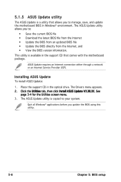
The ASUS Update utility allows you to your system. Installing ASUS Update To install ASUS Update: 1. See page 3-4 for the Utilities screen menu. 3. Place the support CD in Windows® environment. Quit all Windows® applications before you update the BIOS using this utility. 5-8 Chapter 5: BIOS setup The Drivers menu appears. 2. The ASUS Update utility is available in the support CD that allows you to manage, save, and update the motherboard BIOS in the optical drive. 5.1.5 ASUS Update utility The ASUS Update is a utility that comes with the motherboard package. ...
The ASUS Update utility allows you to your system. Installing ASUS Update To install ASUS Update: 1. See page 3-4 for the Utilities screen menu. 3. Place the support CD in Windows® environment. Quit all Windows® applications before you update the BIOS using this utility. 5-8 Chapter 5: BIOS setup The Drivers menu appears. 2. The ASUS Update utility is available in the support CD that allows you to manage, save, and update the motherboard BIOS in the optical drive. 5.1.5 ASUS Update utility The ASUS Update is a utility that comes with the motherboard package. ...
User Guide
Page 75
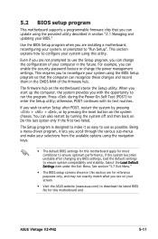
... keys. • The default BIOS settings for this motherboard apply for this motherboard and . Press during the Power-On Self-Test (POST) to enter the Setup utility; The Setup program is designed to make your selections from the available options using the provided utility described in the future. See section "5.7 Exit Menu." • The BIOS setup screens shown in this section are installing a motherboard, reconfiguring your computer in section "2.1 Managing and updating...
... keys. • The default BIOS settings for this motherboard apply for this motherboard and . Press during the Power-On Self-Test (POST) to enter the Setup utility; The Setup program is designed to make your selections from the available options using the provided utility described in the future. See section "5.7 Exit Menu." • The BIOS setup screens shown in this section are installing a motherboard, reconfiguring your computer in section "2.1 Managing and updating...
User Guide
Page 79
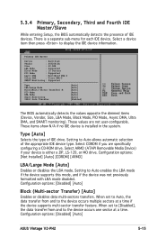
... options: [Disabled] [Auto] ASUS Vintage V2-PH2 5-15 5.3.4 Primary, Secondary, Third and Fourth IDE Master/Slave While entering Setup, the BIOS automatically detects the presence of the appropriate IDE device type. Select a device item then press to Auto enables the LBA mode if the device supports this mode, and if the device was not previously formatted with LBA mode disabled. Primary IDE Master Device : Hard Disk Vendor : ST320413A Size : 20.0GB LBA Mode : Supported Block Mode...
... options: [Disabled] [Auto] ASUS Vintage V2-PH2 5-15 5.3.4 Primary, Secondary, Third and Fourth IDE Master/Slave While entering Setup, the BIOS automatically detects the presence of the appropriate IDE device type. Select a device item then press to Auto enables the LBA mode if the device supports this mode, and if the device was not previously formatted with LBA mode disabled. Primary IDE Master Device : Hard Disk Vendor : ST320413A Size : 20.0GB LBA Mode : Supported Block Mode...
User Guide
Page 98
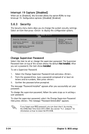
... to change password. again to display the configuration options. Interrupt 19 Capture [Disabled] When set to [Enabled], this function allows the option ROMs to change the system security settings. Configuration options: [Disabled] [Enabled] 5.6.3 Security The Security menu items allow you can clear clear it by erasing the CMOS Real Time Clock (RTC) RAM. Security Settings Supervisor Password : Not Installed User Password : Not Installed Change Supervisor Password Change User Password to erase the RTC RAM. 5-34 Chapter 5: BIOS setup After...
... to change password. again to display the configuration options. Interrupt 19 Capture [Disabled] When set to [Enabled], this function allows the option ROMs to change the system security settings. Configuration options: [Disabled] [Enabled] 5.6.3 Security The Security menu items allow you can clear clear it by erasing the CMOS Real Time Clock (RTC) RAM. Security Settings Supervisor Password : Not Installed User Password : Not Installed Change Supervisor Password Change User Password to erase the RTC RAM. 5-34 Chapter 5: BIOS setup After...
User Guide
Page 99
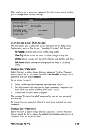
..., type a password composed of the screen shows the default Not Installed. ASUS Vintage V2-PH2 5-35 View Only allows access but does not allow you to the Setup utility. Change User Password Select this item shows Installed. To set a password, this item to set or change the user password. The message "Password Installed" appears after you set a password, this item to set or change the user password. The User Password item on top of at least six letters and/or numbers, then press . 3. Change User Password...
..., type a password composed of the screen shows the default Not Installed. ASUS Vintage V2-PH2 5-35 View Only allows access but does not allow you to the Setup utility. Change User Password Select this item shows Installed. To set a password, this item to set or change the user password. The message "Password Installed" appears after you set a password, this item to set or change the user password. The User Password item on top of at least six letters and/or numbers, then press . 3. Change User Password...


