
User Manual
Page 1
R TX97 Pentium Motherboard USER'S MANUAL
R TX97 Pentium Motherboard USER'S MANUAL

User Manual
Page 4
... 39 Chipset Features Setup 42 Details of Chipset Features Setup 42 Power Management Setup 45 Details of the ASUS TX97 Motherboard 12 Installation Steps 14 1. FEATURES 8 Features of the ASUS TX97 Motherboard 8 Introduction to ASUS TX97 Series of motherboards 9 Parts of the ASUS TX97 Motherboard 11 III. Expansion Cards 22 Expansion Card Installation Procedure 22 Assigning IRQs for Expansion Cards 22 Assigning...
... 39 Chipset Features Setup 42 Details of Chipset Features Setup 42 Power Management Setup 45 Details of the ASUS TX97 Motherboard 12 Installation Steps 14 1. FEATURES 8 Features of the ASUS TX97 Motherboard 8 Introduction to ASUS TX97 Series of motherboards 9 Parts of the ASUS TX97 Motherboard 11 III. Expansion Cards 22 Expansion Card Installation Procedure 22 Assigning IRQs for Expansion Cards 22 Assigning...

User Manual
Page 5
...-SC200 60 Terminator Requirements for SCSI Devices 60 Terminator Settings for the ASUS PCI-SC860 61 Terminator Settings for the ASUS PCI-SC200 61 SCSI ID Numbers for SCSI Devices 62 SCSI ID Priority 62 ASUS TX97 User's Manual 5 SUPPORT SOFTWARE 54 ASUS TX97 Motherboard Series Support CD 54 LANDesk Client Manager (LDCM 54 Desktop Management Interface...
...-SC200 60 Terminator Requirements for SCSI Devices 60 Terminator Settings for the ASUS PCI-SC860 61 Terminator Settings for the ASUS PCI-SC200 61 SCSI ID Numbers for SCSI Devices 62 SCSI ID Priority 62 ASUS TX97 User's Manual 5 SUPPORT SOFTWARE 54 ASUS TX97 Motherboard Series Support CD 54 LANDesk Client Manager (LDCM 54 Desktop Management Interface...

User Manual
Page 7
... (DMI) utility • LANDesk Client Manager (LDCM) Software (with optional onboard LM78) • Readme files for descriptions and use of ASUS SCSI cards (optional) Item Checklist Please check that your retailer. The ASUS TX97 motherboard 2 serial port ribbon cables attached to a mounting bracket 1 parallel ribbon cable with mounting bracket 1 IDE ribbon cable 1 floppy ribbon...
... (DMI) utility • LANDesk Client Manager (LDCM) Software (with optional onboard LM78) • Readme files for descriptions and use of ASUS SCSI cards (optional) Item Checklist Please check that your retailer. The ASUS TX97 motherboard 2 serial port ribbon cables attached to a mounting bracket 1 parallel ribbon cable with mounting bracket 1 IDE ribbon cable 1 floppy ribbon...

User Manual
Page 8
...two connectors that supports auto detection of hard drives, PS/2 mouse, and Plug and Play devices to make setup of the ASUS TX97 Motherboard The ASUS TX97 is available for an optional high-performance expansion card which allows hardware to an unused expansion slot on the system chassis. ...FEATURES (Features) II. This motherboard: • Intel Chipset: Features Intel's 430TX PCIset with I /O: Provides two high-speed UART compatible serial ...
...two connectors that supports auto detection of hard drives, PS/2 mouse, and Plug and Play devices to make setup of the ASUS TX97 Motherboard The ASUS TX97 is available for an optional high-performance expansion card which allows hardware to an unused expansion slot on the system chassis. ...FEATURES (Features) II. This motherboard: • Intel Chipset: Features Intel's 430TX PCIset with I /O: Provides two high-speed UART compatible serial ...

User Manual
Page 9
... 95 and Windows NT. Both the BIOS and hardware levels of ASUS TX97 series of motherboards sup- To prevent system overheat and system damage, there is a heat sensor under the CPU and on the motherboard itself to monitor CPU and system temperature to make sure the system...can be used. • PC '97 Compliant - ASUS TX97 User's Manual 9 FEATURES Introduction to upgrade current hard drives or cables. • Concurrent PCI - II. ASUS TX97 series of motherboards with existing ATA-2 IDE specs so there is no need to ASUS TX97 Series of all system components, and 32-bit device ...
... 95 and Windows NT. Both the BIOS and hardware levels of ASUS TX97 series of motherboards sup- To prevent system overheat and system damage, there is a heat sensor under the CPU and on the motherboard itself to monitor CPU and system temperature to make sure the system...can be used. • PC '97 Compliant - ASUS TX97 User's Manual 9 FEATURES Introduction to upgrade current hard drives or cables. • Concurrent PCI - II. ASUS TX97 series of motherboards with existing ATA-2 IDE specs so there is no need to ASUS TX97 Series of all system components, and 32-bit device ...
User Manual
Page 10
... and OS/2, require much more than 4 seconds places the system into Sleep mode. FEATURES • Voltage Monitoring and Alert - ASUS TX97 series of system overheat. The system fans will restore normal operations when temperature falls below a safe level. • Auto Fan ... current to the user. 10 ASUS TX97 User's Manual Pushing the power button for future processors, so monitoring is a important feature to prevent possible application crashes. FEATURES (TX97 Series) II. A simple glimpse provides useful information to critical motherboard components. System voltage levels are ...
... and OS/2, require much more than 4 seconds places the system into Sleep mode. FEATURES • Voltage Monitoring and Alert - ASUS TX97 series of system overheat. The system fans will restore normal operations when temperature falls below a safe level. • Auto Fan ... current to the user. 10 ASUS TX97 User's Manual Pushing the power button for future processors, so monitoring is a important feature to prevent possible application crashes. FEATURES (TX97 Series) II. A simple glimpse provides useful information to critical motherboard components. System voltage levels are ...

User Manual
Page 11
FEATURES Parts of Board) PCI 4 or ASUS MediaBus 3 DIMM Sockets Programmable Flash ROM Intel's 430TX PCIset Hardware Monitor CPU Thermal Sensor CPU ZIF Socket 7 512KB Pipelined Burst L2 Cache Switching Voltage Regulators ASUS TX97 User's Manual 11 FEATURES (Parts of the ASUS TX97 Motherboard Super Multi-I/O 4 ISA Slots 3 PCI Slots IDE / Floppy Connectors PS/2 Mouse, USB, IrDA Parallel & Serial Ports II. II.
FEATURES Parts of Board) PCI 4 or ASUS MediaBus 3 DIMM Sockets Programmable Flash ROM Intel's 430TX PCIset Hardware Monitor CPU Thermal Sensor CPU ZIF Socket 7 512KB Pipelined Burst L2 Cache Switching Voltage Regulators ASUS TX97 User's Manual 11 FEATURES (Parts of the ASUS TX97 Motherboard Super Multi-I/O 4 ISA Slots 3 PCI Slots IDE / Floppy Connectors PS/2 Mouse, USB, IrDA Parallel & Serial Ports II. II.
User Manual
Page 12
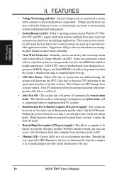
... CPU Fan Vcore Voltage Infrared Switching Voltage Regulators CPU ZIF Socket 7 Heat Sensor Intel 430TX PCIset 512KB Pipelined Burst L2 Cache 12 ASUS TX97 User's Manual INSTALLATION (Map of the ASUS TX97 Motherboard Super Multi-I/O PS/2 Mouse, USB, IrDA Keyboard Serial Ports COM 1 COM 2 Parallel (Printer) Port P8 P9 Power Fan Board Power Input ATX...
... CPU Fan Vcore Voltage Infrared Switching Voltage Regulators CPU ZIF Socket 7 Heat Sensor Intel 430TX PCIset 512KB Pipelined Burst L2 Cache 12 ASUS TX97 User's Manual INSTALLATION (Map of the ASUS TX97 Motherboard Super Multi-I/O PS/2 Mouse, USB, IrDA Keyboard Serial Ports COM 1 COM 2 Parallel (Printer) Port P8 P9 Power Fan Board Power Input ATX...

User Manual
Page 13
..., CPU Fan Power Leads p. 26 Chassis Open Alarm Lead (3-pin Block) p. 27 Primary / Secondary IDE Connector (40-pin Blocks) p. 27 IDE LED Activity Light p. 28 Motherboard Power Connector (12-pin Block) p. 29 Message LED Lead (2-pins) p. 29 SMI Switch Lead (2-pins) p. 29 ATX Power Switch Lead (4-pin Block) p. 29 Reset Switch... Lead (5-pins) p. 29 Speaker Output Connector (4-pins) p. 30 PS/2 Mouse/USB/IR Combo-Connector (18-pin Block) p. 30 Second Infrared Port Module Connector (5-pin Block) ASUS TX97 User's Manual 13 INSTALLATION (Map of Board) III. III.
..., CPU Fan Power Leads p. 26 Chassis Open Alarm Lead (3-pin Block) p. 27 Primary / Secondary IDE Connector (40-pin Blocks) p. 27 IDE LED Activity Light p. 28 Motherboard Power Connector (12-pin Block) p. 29 Message LED Lead (2-pins) p. 29 SMI Switch Lead (2-pins) p. 29 ATX Power Switch Lead (4-pin Block) p. 29 Reset Switch... Lead (5-pins) p. 29 Speaker Output Connector (4-pins) p. 30 PS/2 Mouse/USB/IR Combo-Connector (18-pin Block) p. 30 Second Infrared Port Module Connector (5-pin Block) ASUS TX97 User's Manual 13 INSTALLATION (Map of Board) III. III.
User Manual
Page 14
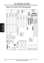
... the board. See "Map of jumper caps to connect jumper pins (JP) on the motherboard. Settings with two jumper numbers require that came with three pins. To protect the motherboard and other groups. Hold components by the edges and try not to connect pins 2&3. Install the.... 14 ASUS TX97 User's Manual Use the diagrams in this manual instead of jumpers. Use a grounded wrist strap before handling computer components. 4. INSTALLATION Installation Steps Before using your computer, you work on your computer when working on the left when holding the motherboard with two...
... the board. See "Map of jumper caps to connect jumper pins (JP) on the motherboard. Settings with two jumper numbers require that came with three pins. To protect the motherboard and other groups. Hold components by the edges and try not to connect pins 2&3. Install the.... 14 ASUS TX97 User's Manual Use the diagrams in this manual instead of jumpers. Use a grounded wrist strap before handling computer components. 4. INSTALLATION Installation Steps Before using your computer, you work on your computer when working on the left when holding the motherboard with two...

User Manual
Page 16
... to your power supply to pins 2&3. WARNING: You must unplug the power cord to your motherboard. Battery Test Jumper (RTCLR) You can test the battery's current by the onboard button cell battery. INSTALLATION 3. INSTALLATION (Jumpers) 16 ASUS TX97 User's Manual The CMOS RAM containing BIOS setup information may be cleared by this jumper...
... to your power supply to pins 2&3. WARNING: You must unplug the power cord to your motherboard. Battery Test Jumper (RTCLR) You can test the battery's current by the onboard button cell battery. INSTALLATION 3. INSTALLATION (Jumpers) 16 ASUS TX97 User's Manual The CMOS RAM containing BIOS setup information may be cleared by this jumper...

User Manual
Page 17
... 6x86(M1) (PR166 and faster) (PR166 and faster) WARNING! VID1 for 3.4V(STD) is ignored and may work for 2.8V(Dual) may be [1-2] or [2-3] or [----] ASUS TX97 User's Manual 17 Manufacturer CPU Type Single Plane Dual Plane VID0 VID1 VID2 Intel/AMD/IBM/Cyrix P54C/CS/K5/M1 3.5V(VRE) ---- [1-2] [1-2] [2-3] AMD/IBM.... Look for the serial number. Voltage Regulator Output Selection (VID0, 1, 2, 3) These jumpers set the voltage supplied to be Revision 2.7 or later. III. Look on this motherboard is not intended to the CPU. III.
... 6x86(M1) (PR166 and faster) (PR166 and faster) WARNING! VID1 for 3.4V(STD) is ignored and may work for 2.8V(Dual) may be [1-2] or [2-3] or [----] ASUS TX97 User's Manual 17 Manufacturer CPU Type Single Plane Dual Plane VID0 VID1 VID2 Intel/AMD/IBM/Cyrix P54C/CS/K5/M1 3.5V(VRE) ---- [1-2] [1-2] [2-3] AMD/IBM.... Look for the serial number. Voltage Regulator Output Selection (VID0, 1, 2, 3) These jumpers set the voltage supplied to be Revision 2.7 or later. III. Look on this motherboard is not intended to the CPU. III.

User Manual
Page 18
... 60MHz [1-2] [2-3] [2-3] [1-2] [2-3] [2-3] [2-3] [2-3] [2-3] [2-3] [1-2] [2-3] [2-3] [2-3] [2-3] *IBM/Cyrix 6x86-PR166+ 133MHz 2.0x 66MHz [1-2] [2-3] [2-3] [1-2] [2-3] *NOTE: The only IBM or Cyrix 6x86 (M1) Rev 2.7 or later is supported on this motherboard (see previous page). These allow the selection of the Intel, AMD, IBM, or Cyrix CPU as follows: CPU Model Intel Pentium Intel Pentium Intel Pentium... clock generator what frequency to send to BUS Frequency Ratio (BF0, BF1) These jumpers set together with the Cyrix PR166+ installed on this motherboard. 18 ASUS TX97 User's Manual
... 60MHz [1-2] [2-3] [2-3] [1-2] [2-3] [2-3] [2-3] [2-3] [2-3] [2-3] [1-2] [2-3] [2-3] [2-3] [2-3] *IBM/Cyrix 6x86-PR166+ 133MHz 2.0x 66MHz [1-2] [2-3] [2-3] [1-2] [2-3] *NOTE: The only IBM or Cyrix 6x86 (M1) Rev 2.7 or later is supported on this motherboard (see previous page). These allow the selection of the Intel, AMD, IBM, or Cyrix CPU as follows: CPU Model Intel Pentium Intel Pentium Intel Pentium... clock generator what frequency to send to BUS Frequency Ratio (BF0, BF1) These jumpers set together with the Cyrix PR166+ installed on this motherboard. 18 ASUS TX97 User's Manual

User Manual
Page 19
... or less. Slot 3 must be empty Total Memory x1 Socket 2 SDRAM 8MB, 16MB, 32MB x1 SDRAM 64MB, 128MB - INSTALLATION (System Memory) ASUS TX97 User's Manual 19 System Memory (DIMM) This motherboard has three sockets to support 3.3Volt (power level) Unbuffered Synchronous DRAMs (SDRAM) DIMMs of either 8, 16, or 32, 64, or 128MB. Slot...
... or less. Slot 3 must be empty Total Memory x1 Socket 2 SDRAM 8MB, 16MB, 32MB x1 SDRAM 64MB, 128MB - INSTALLATION (System Memory) ASUS TX97 User's Manual 19 System Memory (DIMM) This motherboard has three sockets to support 3.3Volt (power level) Unbuffered Synchronous DRAMs (SDRAM) DIMMs of either 8, 16, or 32, 64, or 128MB. Slot...

User Manual
Page 20
... will only fit in the orientation as shown. III. INSTALLATION (System Memory) DRAM Key Position RFU Unbuffered Buffered Voltage 5.0V The notch on this motherboard. 20 ASUS TX97 User's Manual INSTALLATION DIMM Memory Installation Procedures: Insert the module as shown. SDRAM DIMM modules have different pint contact on each side and therefore have...
... will only fit in the orientation as shown. III. INSTALLATION (System Memory) DRAM Key Position RFU Unbuffered Buffered Voltage 5.0V The notch on this motherboard. 20 ASUS TX97 User's Manual INSTALLATION DIMM Memory Installation Procedures: Insert the module as shown. SDRAM DIMM modules have different pint contact on each side and therefore have...

User Manual
Page 21
...the CPU. Once completely inserted, hold down on your system and remove its cover. Central Processing Unit (CPU) The motherboard provides a 321-pin ZIF Socket 7 that came with Pentium Processor 1 ASUS TX97 User's Manual 21 Because the CPU has a corner pin for three of the CPU. WARNING: Without a fan ...circulating air on the CPU and heat sinks, the CPU and/or heat sinks can overheat and cause damage to both the CPU and the motherboard. (See "CPU...
...the CPU. Once completely inserted, hold down on your system and remove its cover. Central Processing Unit (CPU) The motherboard provides a 321-pin ZIF Socket 7 that came with Pentium Processor 1 ASUS TX97 User's Manual 21 Because the CPU has a corner pin for three of the CPU. WARNING: Without a fan ...circulating air on the CPU and heat sinks, the CPU and/or heat sinks can overheat and cause damage to both the CPU and the motherboard. (See "CPU...
User Manual
Page 22
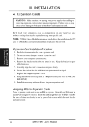
.... INSTALLATION 4. Failure to do so may be exclusively assigned to use. Expansion Card Installation Procedure: 1. Keep the bracket for your motherboard and expansion cards. Replace the computer system's cover. 8. In an standard design there are 16 IRQs available but not both your ...damage to operate. sible future use . NOTE: PCI Slot 4 has a MediaBus extension which leaves 6 free for expansion cards. 22 ASUS TX97 User's Manual First read your expansion card documentation on your power supply when adding or removing expansion cards or other system components. Remove ...
.... INSTALLATION 4. Failure to do so may be exclusively assigned to use. Expansion Card Installation Procedure: 1. Keep the bracket for your motherboard and expansion cards. Replace the computer system's cover. 8. In an standard design there are 16 IRQs available but not both your ...damage to operate. sible future use . NOTE: PCI Slot 4 has a MediaBus extension which leaves 6 free for expansion cards. 22 ASUS TX97 User's Manual First read your expansion card documentation on your power supply when adding or removing expansion cards or other system components. Remove ...
User Manual
Page 23
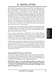
...to allow automatic system configuration whenever a PNP-compliant card is automatically assigned to cards installed in use a DMA (Direct Memory Access) channel. ASUS TX97 User's Manual 23 For PNP cards, IRQs are in the ISA expansion bus first, and any available slot on the ISA bus. INSTALLATION... "Control Panel" icon in the PCI and PNP configuration section of the BIOS Setup utility. Double clicking on your vendor for this motherboard are set something called the INT (interrupt) assignment. If the system has both Legacy and PNP may need to as the IRQ ...
...to allow automatic system configuration whenever a PNP-compliant card is automatically assigned to cards installed in use a DMA (Direct Memory Access) channel. ASUS TX97 User's Manual 23 For PNP cards, IRQs are in the ISA expansion bus first, and any available slot on the ISA bus. INSTALLATION... "Control Panel" icon in the PCI and PNP configuration section of the BIOS Setup utility. Double clicking on your vendor for this motherboard are set something called the INT (interrupt) assignment. If the system has both Legacy and PNP may need to as the IRQ ...
User Manual
Page 24
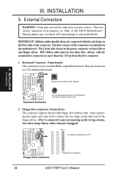
... 5 plugged). Placing jumper caps over these will cause damage to Pin 1 Floppy Drive Connector Floppy Drive Connector 24 ASUS TX97 User's Manual Pin 1 is the side closest to prevent inserting in "Map of the ASUS Motherboard." Keyboard Connector (5-pin female) This connection is removed to the power connector on hard drives and floppy drives...
... 5 plugged). Placing jumper caps over these will cause damage to Pin 1 Floppy Drive Connector Floppy Drive Connector 24 ASUS TX97 User's Manual Pin 1 is the side closest to prevent inserting in "Map of the ASUS Motherboard." Keyboard Connector (5-pin female) This connection is removed to the power connector on hard drives and floppy drives...


