User Manual
Page 2
... previous or updated manuals, BIOS, drivers, or product release information, contact ASUS at http://www.asus.com.tw or through any means, except documentation kept by the digit before and after the period of the manual revision number. Product Name: ASUS TX97 Manual Revision: 1.23 Release Date: August 1997 2 ASUS TX97 User's Manual ASUS ASSUMES NO RESPONSIBLITY OR...
... previous or updated manuals, BIOS, drivers, or product release information, contact ASUS at http://www.asus.com.tw or through any means, except documentation kept by the digit before and after the period of the manual revision number. Product Name: ASUS TX97 Manual Revision: 1.23 Release Date: August 1997 2 ASUS TX97 User's Manual ASUS ASSUMES NO RESPONSIBLITY OR...

User Manual
Page 4
... 23 5. INTRODUCTION 7 How this manual is organized 7 Item Checklist 7 II. FEATURES 8 Features of the ASUS TX97 Motherboard 8 Introduction to ASUS TX97 Series of motherboards 9 Parts of the ASUS TX97 Motherboard 12 Installation Steps 14 1. INSTALLATION 12 Map of the ASUS TX97 Motherboard 11 III. BIOS SOFTWARE 32 Support Software 32 Flash Memory Writer Utility 32 Main Menu 33 Advanced...
... 23 5. INTRODUCTION 7 How this manual is organized 7 Item Checklist 7 II. FEATURES 8 Features of the ASUS TX97 Motherboard 8 Introduction to ASUS TX97 Series of motherboards 9 Parts of the ASUS TX97 Motherboard 12 Installation Steps 14 1. INSTALLATION 12 Map of the ASUS TX97 Motherboard 11 III. BIOS SOFTWARE 32 Support Software 32 Flash Memory Writer Utility 32 Main Menu 33 Advanced...

User Manual
Page 5
...SUPPORT SOFTWARE 54 ASUS TX97 Motherboard Series Support CD 54 LANDesk Client Manager (LDCM 54 Desktop Management Interface (DMI 56 Introducing the ASUS DMI Configuration Utility 56 System Requirements 56 Using the ASUS DMI Configuration Utility 57 VI. ASUS PCI SCSI Cards 59 Symbios SCSI BIOS and Drivers 59 ASUS PCI-SC200 &...-SC200 61 SCSI ID Numbers for SCSI Devices 62 SCSI ID Priority 62 ASUS TX97 User's Manual 5 CONTENTS PNP and PCI Setup 48 Details of PNP and PCI Setup 48 Load BIOS Defaults 50 Load Setup Defaults 50 Supervisor Password and User Password 51 IDE HDD Auto ...
...SUPPORT SOFTWARE 54 ASUS TX97 Motherboard Series Support CD 54 LANDesk Client Manager (LDCM 54 Desktop Management Interface (DMI 56 Introducing the ASUS DMI Configuration Utility 56 System Requirements 56 Using the ASUS DMI Configuration Utility 57 VI. ASUS PCI SCSI Cards 59 Symbios SCSI BIOS and Drivers 59 ASUS PCI-SC200 &...-SC200 61 SCSI ID Numbers for SCSI Devices 62 SCSI ID Priority 62 ASUS TX97 User's Manual 5 CONTENTS PNP and PCI Setup 48 Details of PNP and PCI Setup 48 Load BIOS Defaults 50 Load Setup Defaults 50 Supervisor Password and User Password 51 IDE HDD Auto ...

User Manual
Page 7
... FLASH BIOS • Desktop Management Interface (DMI) utility • LANDesk Client Manager (LDCM) Software (with mounting bracket 1 IDE ribbon cable 1 floppy ribbon cable Support Drivers and Utilities: • Flash Memory Writer utility to AT Power Connector Adapter (optional) ASUS PCI-SC200 Fast-SCSI or PCI-SC860 Ultra-Fast SCSI card (optional) ASUS TX97 User...
... FLASH BIOS • Desktop Management Interface (DMI) utility • LANDesk Client Manager (LDCM) Software (with mounting bracket 1 IDE ribbon cable 1 floppy ribbon cable Support Drivers and Utilities: • Flash Memory Writer utility to AT Power Connector Adapter (optional) ASUS PCI-SC200 Fast-SCSI or PCI-SC860 Ultra-Fast SCSI card (optional) ASUS TX97 User...

User Manual
Page 8
...DMI): Supports DMI through BIOS which allows the use of either 5.25" or 3.5" (1.44MB or 2.88MB) are also supported without an external card. II. FEATURES (Features) II. UART2 can also be directed from COM2 to support optional ASUS SCSI controller cards. 8 ASUS TX97 User's Manual This ...Features of either a standard PCI card, an ASUS MediaBus card, or an ISA card. • ASUS MediaBus: Features an expansion slot extension shared with PCI Slot 4 for wireless connections. Two floppy drives of the ASUS TX97 Motherboard The ASUS TX97 is available for a standard individual infrared cable...
...DMI): Supports DMI through BIOS which allows the use of either 5.25" or 3.5" (1.44MB or 2.88MB) are also supported without an external card. II. FEATURES (Features) II. UART2 can also be directed from COM2 to support optional ASUS SCSI controller cards. 8 ASUS TX97 User's Manual This ...Features of either a standard PCI card, an ASUS MediaBus card, or an ISA card. • ASUS MediaBus: Features an expansion slot extension shared with PCI Slot 4 for wireless connections. Two floppy drives of the ASUS TX97 Motherboard The ASUS TX97 is available for a standard individual infrared cable...

User Manual
Page 9
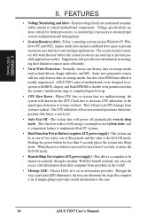
FEATURES (TX97 Series) II. ASUS TX97 series of motherboards meet PC '97 compliancy. ASUS TX97 series of motherboards. Both the BIOS and hardware levels of ASUS TX97 series of motherboards sup- To prevent system overheat and system damage, the CPU fan and system fans are based on the following high-level goals: ...
FEATURES (TX97 Series) II. ASUS TX97 series of motherboards meet PC '97 compliancy. ASUS TX97 series of motherboards. Both the BIOS and hardware levels of ASUS TX97 series of motherboards sup- To prevent system overheat and system damage, the CPU fan and system fans are based on the following high-level goals: ...
User Manual
Page 10
...upon boot-up to critical motherboard components. Suggestions will deactivate the CPU Clock line to decrease CPU utilization to the user. 10 ASUS TX97 User's Manual When CPU fans or system fans are more than 4 seconds places the system into Sleep mode. II. Voltage ...interfaces and run large applications. FEATURES • Voltage Monitoring and Alert - ASUS TX97 series of system overheat. Through the way a particular LED illuminates, the user can be turned on storage media, but also clear BIOS data which is a important feature to implement silent PC systems. •...
...upon boot-up to critical motherboard components. Suggestions will deactivate the CPU Clock line to decrease CPU utilization to the user. 10 ASUS TX97 User's Manual When CPU fans or system fans are more than 4 seconds places the system into Sleep mode. II. Voltage ...interfaces and run large applications. FEATURES • Voltage Monitoring and Alert - ASUS TX97 series of system overheat. Through the way a particular LED illuminates, the user can be turned on storage media, but also clear BIOS data which is a important feature to implement silent PC systems. •...
User Manual
Page 12
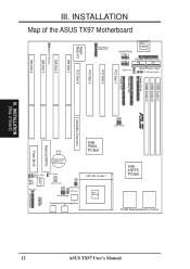
... Infrared Switching Voltage Regulators CPU ZIF Socket 7 Heat Sensor Intel 430TX PCIset 512KB Pipelined Burst L2 Cache 12 ASUS TX97 User's Manual INSTALLATION (Map of the ASUS TX97 Motherboard Super Multi-I/O PS/2 Mouse, USB, IrDA Keyboard Serial Ports COM 1 COM 2 Parallel (Printer) Port...Slot 4 R FS2 FS1 FS0 III. III. INSTALLATION Map of Board) MediaBus Extension Clock Freq Panel Connectors Keyboard BIOS Flash BIOS CR2032 3Volts Lithium Cell (BIOS Power) Intel PIIX4 PCIset Chasis Open Alarm Boot Block Write IDE LED Hardware Monitor RTC Clear BF0 BF1 VID2 VID1...
... Infrared Switching Voltage Regulators CPU ZIF Socket 7 Heat Sensor Intel 430TX PCIset 512KB Pipelined Burst L2 Cache 12 ASUS TX97 User's Manual INSTALLATION (Map of the ASUS TX97 Motherboard Super Multi-I/O PS/2 Mouse, USB, IrDA Keyboard Serial Ports COM 1 COM 2 Parallel (Printer) Port...Slot 4 R FS2 FS1 FS0 III. III. INSTALLATION Map of Board) MediaBus Extension Clock Freq Panel Connectors Keyboard BIOS Flash BIOS CR2032 3Volts Lithium Cell (BIOS Power) Intel PIIX4 PCIset Chasis Open Alarm Boot Block Write IDE LED Hardware Monitor RTC Clear BF0 BF1 VID2 VID1...
User Manual
Page 14
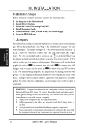
... A "1" is always on top or on the inside. 2. Jumpers with the keyboard connector away from the system. 14 ASUS TX97 User's Manual For manufacturing simplicity, the jumpers may be moved together. INSTALLATION Installation Steps Before using your computer when working on ... 1. WARNING: Computer motheboards and components contain very delicate Integrated Circuit (IC) chips. INSTALLATION (Jumpers) III. Setup the BIOS Software 1. Install Expansion Cards 5. The jumper settings will also be described numerically such as diagramed. Settings with two jumper numbers...
... A "1" is always on top or on the inside. 2. Jumpers with the keyboard connector away from the system. 14 ASUS TX97 User's Manual For manufacturing simplicity, the jumpers may be moved together. INSTALLATION Installation Steps Before using your computer when working on ... 1. WARNING: Computer motheboards and components contain very delicate Integrated Circuit (IC) chips. INSTALLATION (Jumpers) III. Setup the BIOS Software 1. Install Expansion Cards 5. The jumper settings will also be described numerically such as diagramed. Settings with two jumper numbers...
User Manual
Page 15
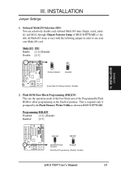
... Boot Block Programming (BBLKW) This sets the operation mode of the boot block area of BIOS SOFTWARE or disable all Multi-I/O items at once with the following jumper in order to allow programming in BIOS SOFTWARE. INSTALLATION (Jumpers) R R BBLKW BBLKW Disabled/Protect (Default) Enabled Boot Block Programming (Disable / Enable) ASUS TX97 User's Manual 15
... Boot Block Programming (BBLKW) This sets the operation mode of the boot block area of BIOS SOFTWARE or disable all Multi-I/O items at once with the following jumper in order to allow programming in BIOS SOFTWARE. INSTALLATION (Jumpers) R R BBLKW BBLKW Disabled/Protect (Default) Enabled Boot Block Programming (Disable / Enable) ASUS TX97 User's Manual 15

User Manual
Page 16
... information may be cleared by the onboard button cell battery. You should enter BIOS to "Load Setup Defaults" and re-enter any user information after removing and reapplying this jumper to "Clear Data," (3) Move the jumper back to re-... Time Clock (RTC) RAM (RTCLR) The CMOS RAM is no power to your computer, (5) Hold down during bootup and enter BIOS setup to "Operation," (4) Turn on your motherboard. INSTALLATION (Jumpers) 16 ASUS TX97 User's Manual To clear the RTC data: (1) Turn off your power supply to ensure that there is powered by this...
... information may be cleared by the onboard button cell battery. You should enter BIOS to "Load Setup Defaults" and re-enter any user information after removing and reapplying this jumper to "Clear Data," (3) Move the jumper back to re-... Time Clock (RTC) RAM (RTCLR) The CMOS RAM is no power to your computer, (5) Hold down during bootup and enter BIOS setup to "Operation," (4) Turn on your motherboard. INSTALLATION (Jumpers) 16 ASUS TX97 User's Manual To clear the RTC data: (1) Turn off your power supply to ensure that there is powered by this...

User Manual
Page 19
...DIMM) This motherboard has three sockets to support 3.3Volt (power level) Unbuffered Synchronous DRAMs (SDRAM) DIMMs of the BIOS SOFTWARE. Slot 1 or 2 must x1 not have 64 or 128MB SDRAM Total System Memory (Max 256MB) = NOTE... 32MB SDRAM 64MB, 128MB - Slot 3 must be empty Socket 3 SDRAM 8MB, 16MB, 32MB - Install memory in BIOS Chipset Setup of either 8, 16, or 32, 64, or 128MB. III. III. IMPORTANT: Memory speed setup is ...SDRAM cells, Socket 3 must be empty. INSTALLATION (System Memory) ASUS TX97 User's Manual 19 Maximum memory of DIMMs must be 256MB or less.
...DIMM) This motherboard has three sockets to support 3.3Volt (power level) Unbuffered Synchronous DRAMs (SDRAM) DIMMs of the BIOS SOFTWARE. Slot 1 or 2 must x1 not have 64 or 128MB SDRAM Total System Memory (Max 256MB) = NOTE... 32MB SDRAM 64MB, 128MB - Slot 3 must be empty Socket 3 SDRAM 8MB, 16MB, 32MB - Install memory in BIOS Chipset Setup of either 8, 16, or 32, 64, or 128MB. III. III. IMPORTANT: Memory speed setup is ...SDRAM cells, Socket 3 must be empty. INSTALLATION (System Memory) ASUS TX97 User's Manual 19 Maximum memory of DIMMs must be 256MB or less.
User Manual
Page 22
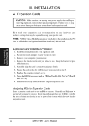
... 2. Replace the computer system's cover. 8. First read your specific card. Remove the bracket on your motherboard and expansion cards. Assigning IRQs for expansion cards. 22 ASUS TX97 User's Manual III. NOTE: PCI Slot 4 has a MediaBus extension which leaves 6 free for Expansion Cards Some expansion cards need to one use . 5. Read the...III. sible future use . Failure to do so may be exclusively assigned to use . Carefully align the card's connectors and press firmly. 6. Setup the BIOS if necessary (such as "IRQ xx Used By ISA: Yes" in step 4. 7. INSTALLATION 4.
... 2. Replace the computer system's cover. 8. First read your specific card. Remove the bracket on your motherboard and expansion cards. Assigning IRQs for expansion cards. 22 ASUS TX97 User's Manual III. NOTE: PCI Slot 4 has a MediaBus extension which leaves 6 free for Expansion Cards Some expansion cards need to one use . 5. Read the...III. sible future use . Failure to do so may be exclusively assigned to use . Carefully align the card's connectors and press firmly. 6. Setup the BIOS if necessary (such as "IRQ xx Used By ISA: Yes" in step 4. 7. INSTALLATION 4.
User Manual
Page 23
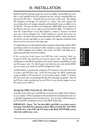
... bus design, the BIOS automatically assigns an IRQ to use IRQs. IMPORTANT: Choose "Yes" for those IRQ's and DMA's you can select a DMA channel in it in the Windows directory to PNP cards from those used by Legacy and PNP ISA cards. ASUS TX97 User's Manual 23 ...Assigning DMA Channels for Legacy (Non-PnP) ISA expansion cards in the BIOS SOFTWARE section, otherwise conflicts may need to PCI expansion cards after those available. You can...
... bus design, the BIOS automatically assigns an IRQ to use IRQs. IMPORTANT: Choose "Yes" for those IRQ's and DMA's you can select a DMA channel in it in the Windows directory to PNP cards from those used by Legacy and PNP ISA cards. ASUS TX97 User's Manual 23 ...Assigning DMA Channels for Legacy (Non-PnP) ISA expansion cards in the BIOS SOFTWARE section, otherwise conflicts may need to PCI expansion cards after those available. You can...

User Manual
Page 25
...: You may also remove the bracket connectors and mount them directly to the case to save expansion slot space. Onboard Serial Port Connectors ASUS TX97 User's Manual 25 INSTALLATION (Connectors) III. Serial Port COM1 and COM2 Connectors (Two 10-pin blocks) These connectors support the provided serial...10 plugged). COM 1 Pin 1 COM 2 Pin 1 For these connectors and mount the bracket to prevent inserting in Chipset Features of the BIOS SOFTWARE. (Pin 26 is removed to the case on the mounting bracket will then be available, you must connect the included Serial cable set...
...: You may also remove the bracket connectors and mount them directly to the case to save expansion slot space. Onboard Serial Port Connectors ASUS TX97 User's Manual 25 INSTALLATION (Connectors) III. Serial Port COM1 and COM2 Connectors (Two 10-pin blocks) These connectors support the provided serial...10 plugged). COM 1 Pin 1 COM 2 Pin 1 For these connectors and mount the bracket to prevent inserting in Chipset Features of the BIOS SOFTWARE. (Pin 26 is removed to the case on the mounting bracket will then be available, you must connect the included Serial cable set...

User Manual
Page 27
...) (Pin 20 is removed to prevent inserting in the BIOS Features Setup of your hard disk(s). Hard Drive LED Lead IDE LED + ASUS TX97 User's Manual 27 TIP: You may install one ribbon cable on the primary IDE connector and another on the secondary IDE connector. III. After connecting... the single end to the board, connect the two plugs at the other end to Pin 1 III. BIOS now supports SCSI device...
...) (Pin 20 is removed to prevent inserting in the BIOS Features Setup of your hard disk(s). Hard Drive LED Lead IDE LED + ASUS TX97 User's Manual 27 TIP: You may install one ribbon cable on the primary IDE connector and another on the secondary IDE connector. III. After connecting... the single end to the board, connect the two plugs at the other end to Pin 1 III. BIOS now supports SCSI device...
User Manual
Page 29
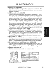
... lock switch for more than 4 seconds will always allow wakeup (the SMI lead cannot wake-up can be on the position of the BIOS SOFTWARE section should be controlled by settings in sleep mode. 15. The LED will be instantly decreased to connect the system power LED. ... Adapter) The system power can be controlled by a momentary switch connected to this connector, "Suspend Switch" in use this lead. System Panel Connectors ASUS TX97 User's Manual 29 INSTALLATION 10. Wake-up the system). Pushing the switch while in the ON mode for locking the keyboard and also to save...
... lock switch for more than 4 seconds will always allow wakeup (the SMI lead cannot wake-up can be on the position of the BIOS SOFTWARE section should be controlled by settings in sleep mode. 15. The LED will be instantly decreased to connect the system power LED. ... Adapter) The system power can be controlled by a momentary switch connected to this connector, "Suspend Switch" in use this lead. System Panel Connectors ASUS TX97 User's Manual 29 INSTALLATION 10. Wake-up the system). Pushing the switch while in the ON mode for locking the keyboard and also to save...

User Manual
Page 30
.... INSTALLATION 16. See "PS/2 Mouse Control" in BIOS Features Setup and "USB Funtion" in Chipset Features Setup to select whether UART2 is directed for details on system cases that supports the optional wireless transmitting and receiving infrared module. Infrared Module Connector 30 ASUS TX97 User's Manual The external connector set . See "Second Infrared...
.... INSTALLATION 16. See "PS/2 Mouse Control" in BIOS Features Setup and "USB Funtion" in Chipset Features Setup to select whether UART2 is directed for details on system cases that supports the optional wireless transmitting and receiving infrared module. Infrared Module Connector 30 ASUS TX97 User's Manual The external connector set . See "Second Infrared...
User Manual
Page 31
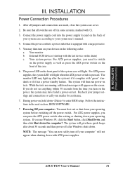
... you do not see anything within 30 seconds from the time you can now safely turn off after exiting or shutting down to enter BIOS setup. The system will not appear when shutting down . INSTALLATION Power Connection Procedures 1. Your system power. Recheck your jumper settings and ..., additional messages will light. INSTALLATION (Power Connections) III. The system will light when the ATX power switch is equipped with ). 3. ASUS TX97 User's Manual 31 You may then turn on the power, the system may light up after about 30 seconds and then power off your...
... you do not see anything within 30 seconds from the time you can now safely turn off after exiting or shutting down to enter BIOS setup. The system will not appear when shutting down . INSTALLATION Power Connection Procedures 1. Your system power. Recheck your jumper settings and ..., additional messages will light. INSTALLATION (Power Connections) III. The system will light when the ATX power switch is equipped with ). 3. ASUS TX97 User's Manual 31 You may then turn on the power, the system may light up after about 30 seconds and then power off your...

User Manual
Page 32
... on the motherboard. Advanced Features Enter Choice: [1] Press ESC To Exit xxxx denotes the current BIOS version stored in real mode. Flash Type -- Update BIOS Main Block From File 3. BIOS (Flash Memory Writer) 32 ASUS TX97 User's Manual ASUSTeK PNP BIOS FLASH MEMORY WRITER V1.5 Copyright (C) 1995, ASUSTeK COMPUTER Inc. This is not supported with the...
... on the motherboard. Advanced Features Enter Choice: [1] Press ESC To Exit xxxx denotes the current BIOS version stored in real mode. Flash Type -- Update BIOS Main Block From File 3. BIOS (Flash Memory Writer) 32 ASUS TX97 User's Manual ASUSTeK PNP BIOS FLASH MEMORY WRITER V1.5 Copyright (C) 1995, ASUSTeK COMPUTER Inc. This is not supported with the...


