
User Manual
Page 1
IMPORTANT: This preliminary copy is for review purposes only and is subject to errors and ongoing modifications. R TX97-XV Pentium® ATX Motherboard USER'S MANUAL
IMPORTANT: This preliminary copy is for review purposes only and is subject to errors and ongoing modifications. R TX97-XV Pentium® ATX Motherboard USER'S MANUAL
User Manual
Page 2
... or data, interruption of business, or for each board design represented by the third digit in the manual revision number. Product Name: ASUS TX97-XV Manual Revision: 1.13 Release Date: April 1997 2 ASUS TX97-XV User's Manual Products mentioned in this manual or product. USER'S NOTICE No part of this product, including the product and software may be reproduced, transmitted, transcribed, stored...
... or data, interruption of business, or for each board design represented by the third digit in the manual revision number. Product Name: ASUS TX97-XV Manual Revision: 1.13 Release Date: April 1997 2 ASUS TX97-XV User's Manual Products mentioned in this manual or product. USER'S NOTICE No part of this product, including the product and software may be reproduced, transmitted, transcribed, stored...
User Manual
Page 3
... Support: Fax: 886-2-895-9254 BBS: 886-2-896-4667 Email: tsd@asus.com.tw WWW: http://www.asus.com.tw/ Gopher: gopher.asus.com.tw FTP: ftp.asus.com.tw/pub/ASUS ASUS COMPUTER INTERNATIONAL Marketing Info: Address: 721 Charcot Avenue, San Jose, CA ...asus.com.tw Technical Support: BBS: 1-408-474-0555 Email: tsd-usa@asus.com.tw ASUS COMPUTER GmbH Marketing Info: Address: Harkort Str. 25, 40880 Ratingen, BRD, Germany Telephone: 49-2102-445011 Fax: 49-2102-442066 Email: info-ger@asus.com.tw Technical Support: BBS: 49-2102-448690 Email: tsd-ger@asus.com.tw ASUS TX97-XV User's Manual...
... Support: Fax: 886-2-895-9254 BBS: 886-2-896-4667 Email: tsd@asus.com.tw WWW: http://www.asus.com.tw/ Gopher: gopher.asus.com.tw FTP: ftp.asus.com.tw/pub/ASUS ASUS COMPUTER INTERNATIONAL Marketing Info: Address: 721 Charcot Avenue, San Jose, CA ...asus.com.tw Technical Support: BBS: 1-408-474-0555 Email: tsd-usa@asus.com.tw ASUS COMPUTER GmbH Marketing Info: Address: Harkort Str. 25, 40880 Ratingen, BRD, Germany Telephone: 49-2102-445011 Fax: 49-2102-442066 Email: info-ger@asus.com.tw Technical Support: BBS: 49-2102-448690 Email: tsd-ger@asus.com.tw ASUS TX97-XV User's Manual...
User Manual
Page 4
... and PCI Setup 50 Details of the ASUS Motherboard 12 Installation Steps 14 1. External Connectors 26 Power Connection Procedures 33 IV. SUPPORT SOFTWARE 56 ASUS TX97 Motherboard Series Support CD 56 LANDesk Client Manager (LDCM 56 4 ASUS TX97-XV User's Manual INSTALLATION 12 Map of PNP and PCI ...Setup 50 Load BIOS Defaults 52 Load Setup Defaults 52 Supervisor Password and User Password 53 IDE HDD Auto ...
... and PCI Setup 50 Details of the ASUS Motherboard 12 Installation Steps 14 1. External Connectors 26 Power Connection Procedures 33 IV. SUPPORT SOFTWARE 56 ASUS TX97 Motherboard Series Support CD 56 LANDesk Client Manager (LDCM 56 4 ASUS TX97-XV User's Manual INSTALLATION 12 Map of PNP and PCI ...Setup 50 Load BIOS Defaults 52 Load Setup Defaults 52 Supervisor Password and User Password 53 IDE HDD Auto ...
User Manual
Page 5
... Installation 67 Software MPEG & Video Player 71 Windows 95 Display Settings 72 VII. CONTENTS Desktop Management Interface (DMI 58 Introducing the ASUS DMI Configuration Utility 58 System Requirements 58 Using the ASUS DMI Configuration Utility 59 Notes 59 R ATI VGA Series 65 VI. Troubleshooting 99 Diagnostics 99 Troubleshooting 99 System Lockup 99 ASUS TX97-XV User's Manual 5
... Installation 67 Software MPEG & Video Player 71 Windows 95 Display Settings 72 VII. CONTENTS Desktop Management Interface (DMI 58 Introducing the ASUS DMI Configuration Utility 58 System Requirements 58 Using the ASUS DMI Configuration Utility 59 Notes 59 R ATI VGA Series 65 VI. Troubleshooting 99 Diagnostics 99 Troubleshooting 99 System Lockup 99 ASUS TX97-XV User's Manual 5
User Manual
Page 6
...the monitor to the graphics card is encouraged to try to correct the interference by one or more of Communications. 6 ASUS TX97-XV User's Manual These limits are designed to which can radiate radio frequency energy and, if not installed and used in accordance with FCC... pursuant to radio communications. FCC & DOC COMPLIANCE Federal Communications Commission Statement This device complies with the limits for compliance could void the user's authority to the following measures: • Re-orient or relocate the receiving antenna. • Increase the separation between the equipment ...
...the monitor to the graphics card is encouraged to try to correct the interference by one or more of Communications. 6 ASUS TX97-XV User's Manual These limits are designed to which can radiate radio frequency energy and, if not installed and used in accordance with FCC... pursuant to radio communications. FCC & DOC COMPLIANCE Federal Communications Commission Statement This device complies with the limits for compliance could void the user's authority to the following measures: • Re-orient or relocate the receiving antenna. • Increase the separation between the equipment ...

User Manual
Page 7
... you discover damaged or missing items, please contact your package is divided into the following sections: I -A16C Audio Card ASUS TX97-XV User's Manual 7 Installation: Instructions on setting up the motherboard. ASUS I . Windows 95: Audio Software Manual (with ASUS I-A16C CD bundle only) • VGA Drivers and utilities • Readme files for descriptions and use of software drivers...
... you discover damaged or missing items, please contact your package is divided into the following sections: I -A16C Audio Card ASUS TX97-XV User's Manual 7 Installation: Instructions on setting up the motherboard. ASUS I . Windows 95: Audio Software Manual (with ASUS I-A16C CD bundle only) • VGA Drivers and utilities • Readme files for descriptions and use of software drivers...
User Manual
Page 8
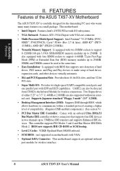
... drives, PS/2 mouse, and Plug and Play devices to communicate within a standard protocol creating a higher level of the ASUS TX97-XV Motherboard The ASUS TX97-XV is carefully designed for wireless connections. Supports Japanese standard "Floppy 3 mode" (3.5" 1.2MB). • Desktop Management Interface...: Is equipped with VGA) • Optional IrDA Connector: This motherboard supports an optional infrared port module for wireless interface. 8 ASUS TX97-XV User's Manual This controller supports PIO Modes 3 and 4 and Bus Master IDE DMA Mode 2. UART2 can also be used at the same ...
... drives, PS/2 mouse, and Plug and Play devices to communicate within a standard protocol creating a higher level of the ASUS TX97-XV Motherboard The ASUS TX97-XV is carefully designed for wireless connections. Supports Japanese standard "Floppy 3 mode" (3.5" 1.2MB). • Desktop Management Interface...: Is equipped with VGA) • Optional IrDA Connector: This motherboard supports an optional infrared port module for wireless interface. 8 ASUS TX97-XV User's Manual This controller supports PIO Modes 3 and 4 and Bus Master IDE DMA Mode 2. UART2 can also be used at the same ...
User Manual
Page 9
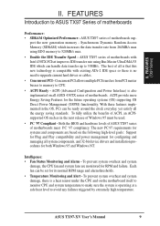
... for RPM and failure. With these features implemented in the next release of motherboards. Both the BIOS and hardware levels of ASUS TX97 series of motherboards sup- Each fan can handle data transfer up to upgrade current hard drives or cables. • Concurrent ...ASUS TX97 Series of ACPI, an ACPIsupported OS such as in the OS, PCs can be set for both Windows 95 and Windows NT. To fully utilize the benefits of motherboards Performance: • SDRAM Optimized Performance - Intelligence: • Fan Status Monitoring and Alarm - FEATURES (TX97 Series) II. ASUS TX97-XV User's Manual...
... for RPM and failure. With these features implemented in the next release of motherboards. Both the BIOS and hardware levels of ASUS TX97 series of motherboards sup- Each fan can handle data transfer up to upgrade current hard drives or cables. • Concurrent ...ASUS TX97 Series of ACPI, an ACPIsupported OS such as in the OS, PCs can be set for both Windows 95 and Windows NT. To fully utilize the benefits of motherboards Performance: • SDRAM Optimized Performance - Intelligence: • Fan Status Monitoring and Alarm - FEATURES (TX97 Series) II. ASUS TX97-XV User's Manual...
User Manual
Page 10
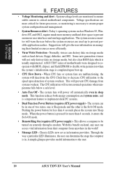
... Sleep mode. The CPU utilization will power off automatically even in . This function reduces both energy consumption and system noise, and is necessary to the user. 10 ASUS TX97-XV User's Manual A simple glimpse provides useful information to ensure proper system configuration and management. • System Resources Alert - Normally, viruses can determine the stage the computer...
... Sleep mode. The CPU utilization will power off automatically even in . This function reduces both energy consumption and system noise, and is necessary to the user. 10 ASUS TX97-XV User's Manual A simple glimpse provides useful information to ensure proper system configuration and management. • System Resources Alert - Normally, viruses can determine the stage the computer...
User Manual
Page 11
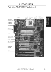
II. FEATURES (Parts of the ASUS TX97-XV Motherboard T: PS/2 Mouse B: PS/2 Keyboard T: USB Port 1 B: USB Port 2 COM 1 T: Parallel Conn. B: Serial / VGA VGA Connector 1MB VGA Memory (upgradable to 2MB) ATI VGA 4 PCI Slots Hardware Monitor Programmable Flash ROM 3 ISA Slots 2 DIMM Sockets CPU ZIF CPU Thermal Intel 430TX 512KB Pipelined Socket 7 Sensor PCIset Burst L2 Cache ASUS TX97-XV User's Manual 11 FEATURES Parts of Board) II.
II. FEATURES (Parts of the ASUS TX97-XV Motherboard T: PS/2 Mouse B: PS/2 Keyboard T: USB Port 1 B: USB Port 2 COM 1 T: Parallel Conn. B: Serial / VGA VGA Connector 1MB VGA Memory (upgradable to 2MB) ATI VGA 4 PCI Slots Hardware Monitor Programmable Flash ROM 3 ISA Slots 2 DIMM Sockets CPU ZIF CPU Thermal Intel 430TX 512KB Pipelined Socket 7 Sensor PCIset Burst L2 Cache ASUS TX97-XV User's Manual 11 FEATURES Parts of Board) II.
User Manual
Page 12
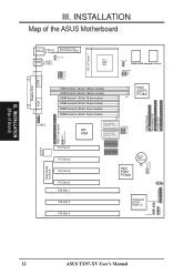
III. ISA Slot 2 ISA Slot 3 Keyboard BIOS/ Multi-I/O Chassis open CHASSIS FAN 12 ASUS TX97-XV User's Manual RATIO BF1 BF0 COM 1 01 01 23 23 32 10 Floppy Drives Secondary IDE Primary IDE VGA COM 2 DIMM Socket 1 (64-bit, 168-pin module) ... USB T: USB 1 B: USB 2 PWR_FAN VID2 VID1 VID0 CPU Voltage CPU ZIF Socket 7 Heat Sensor CPU_FAN 256KB/512KB Onboard L2 Cache FREQ. INSTALLATION (Map of the ASUS Motherboard Parallel Port PS/2 T: Mouse B: Keyboard Board Power Input for BIOS PCI Slot 1 PCI Slot 2 PCI Slot 3 PCI Slot 4 ISA Slot 1 512KB DRAM 512KB DRAM...
III. ISA Slot 2 ISA Slot 3 Keyboard BIOS/ Multi-I/O Chassis open CHASSIS FAN 12 ASUS TX97-XV User's Manual RATIO BF1 BF0 COM 1 01 01 23 23 32 10 Floppy Drives Secondary IDE Primary IDE VGA COM 2 DIMM Socket 1 (64-bit, 168-pin module) ... USB T: USB 1 B: USB 2 PWR_FAN VID2 VID1 VID0 CPU Voltage CPU ZIF Socket 7 Heat Sensor CPU_FAN 256KB/512KB Onboard L2 Cache FREQ. INSTALLATION (Map of the ASUS Motherboard Parallel Port PS/2 T: Mouse B: Keyboard Board Power Input for BIOS PCI Slot 1 PCI Slot 2 PCI Slot 3 PCI Slot 4 ISA Slot 1 512KB DRAM 512KB DRAM...
User Manual
Page 13
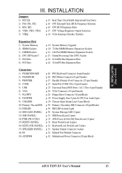
... Lead (2-pins) p. 31 Keyboard Lock Switch Lead (5-pins) p. 31 Speaker Output Connector (4-pins) p. 32 Infrared Port Module Connector p. 32 Motherboard Power Connector (20-pin Block) ASUS TX97-XV User's Manual 13
... Lead (2-pins) p. 31 Keyboard Lock Switch Lead (5-pins) p. 31 Speaker Output Connector (4-pins) p. 32 Infrared Port Module Connector p. 32 Motherboard Power Connector (20-pin Block) ASUS TX97-XV User's Manual 13
User Manual
Page 14
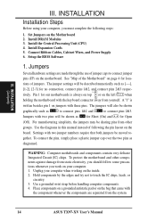
... following the pin layout on page 4 for no connection, connect pins 1&2, and connect pins 2&3 respec- See "Map of following steps: 1. Use the diagrams in this manual instead of the Motherboard" on the board. To connect the pins, simply place a plastic jumper cap over the two pins as [----], [1-2], [2-3] for loca- WARNING: Computer..., the jumpers may be described numerically such as diagramed. The jumper settings will be sharing pins from other components against damage from the system. 14 ASUS TX97-XV User's Manual
... following the pin layout on page 4 for no connection, connect pins 1&2, and connect pins 2&3 respec- See "Map of following steps: 1. Use the diagrams in this manual instead of the Motherboard" on the board. To connect the pins, simply place a plastic jumper cap over the two pins as [----], [1-2], [2-3] for loca- WARNING: Computer..., the jumpers may be described numerically such as diagramed. The jumper settings will be sharing pins from other components against damage from the system. 14 ASUS TX97-XV User's Manual

User Manual
Page 15
...be cleared by the onboard button cell battery. You should enter BIOS to "Load Setup Defaults" and re-enter any user information after removing and reapplying this jumper and attaching a current meter to pins 2&3. RTC RAM Operation Clear Data RTCLR ...user preferences. Real Time Clock (RTC) RAM (RTCLR) The CMOS RAM is no power to your computer, (5) Hold down during bootup and enter BIOS setup to "Operation," (4) Turn on your motherboard. Battery Test Jumper (RTCLR) You can test the battery's current by removing this jumper. INSTALLATION (Jumpers) ASUS TX97-XV User's Manual...
...be cleared by the onboard button cell battery. You should enter BIOS to "Load Setup Defaults" and re-enter any user information after removing and reapplying this jumper and attaching a current meter to pins 2&3. RTC RAM Operation Clear Data RTCLR ...user preferences. Real Time Clock (RTC) RAM (RTCLR) The CMOS RAM is no power to your computer, (5) Hold down during bootup and enter BIOS setup to "Operation," (4) Turn on your motherboard. Battery Test Jumper (RTCLR) You can test the battery's current by removing this jumper. INSTALLATION (Jumpers) ASUS TX97-XV User's Manual...
User Manual
Page 16
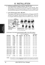
... clock generator what frequency to send to BUS Frequency Ratio (BF0, BF1) These jumpers set together with the Cyrix 166+ installed on this motherboard. 16 ASUS TX97-XV User's Manual
... clock generator what frequency to send to BUS Frequency Ratio (BF0, BF1) These jumpers set together with the Cyrix 166+ installed on this motherboard. 16 ASUS TX97-XV User's Manual
User Manual
Page 17
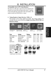
...-3) [2-3] [2-3] [1-2] [2-3] [2-3] [2-3] VID2 VID1 VID0 VID2 VID1 VID0 VID2 VID1 VID0 VID2 VID1 VID0 Voltage Regulator Output Selection 1 2 3 3.5Volts (VRE) 1 2 3 2.8Volts 1 2 3 3.4Volts (STD) 1 2 3 2.7Volts 1 2 3 3.2Volts 1 2 3 2.5Volts 1 2 3 2.9Volts ASUS TX97-XV User's Manual 17 INSTALLATION (System Memory) III. INSTALLATION Compatible Cyrix CPU Identification The only Cyrix CPU that is supported on the underside of the CPU for the...
...-3) [2-3] [2-3] [1-2] [2-3] [2-3] [2-3] VID2 VID1 VID0 VID2 VID1 VID0 VID2 VID1 VID0 VID2 VID1 VID0 Voltage Regulator Output Selection 1 2 3 3.5Volts (VRE) 1 2 3 2.8Volts 1 2 3 3.4Volts (STD) 1 2 3 2.7Volts 1 2 3 3.2Volts 1 2 3 2.5Volts 1 2 3 2.9Volts ASUS TX97-XV User's Manual 17 INSTALLATION (System Memory) III. INSTALLATION Compatible Cyrix CPU Identification The only Cyrix CPU that is supported on the underside of the CPU for the...
User Manual
Page 18
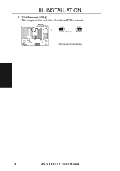
VGA Interrupt (VIRQ) This jumper enables or disables the onboard VGA's interrupt. VIRQ Disable (Default) VIRQ Enable VGA Interrupt (Disable/Enable) 18 ASUS TX97-XV User's Manual III. INSTALLATION 5.
VGA Interrupt (VIRQ) This jumper enables or disables the onboard VGA's interrupt. VIRQ Disable (Default) VIRQ Enable VGA Interrupt (Disable/Enable) 18 ASUS TX97-XV User's Manual III. INSTALLATION 5.
User Manual
Page 19
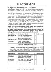
...) 8MB, 16MB, 32MB, 64MB, 128MB 168-pin SDRAM or EDO DIMM (SIMM Sockets must be empty) Total System Memory (Max 256MB) Total Memory x1 x1 = ASUS TX97-XV User's Manual 19 System Memory (SIMM & DIMM) This motherboard supports four 72-pin, 32-bit SIMMs (Single Inline Memory Modules) of the DIMM module takes up half...
...) 8MB, 16MB, 32MB, 64MB, 128MB 168-pin SDRAM or EDO DIMM (SIMM Sockets must be empty) Total System Memory (Max 256MB) Total Memory x1 x1 = ASUS TX97-XV User's Manual 19 System Memory (SIMM & DIMM) This motherboard supports four 72-pin, 32-bit SIMMs (Single Inline Memory Modules) of the DIMM module takes up half...
User Manual
Page 20
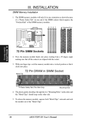
... the sides and the "Metal Clips" should snap on one end of the SIMM sockets which requires the "Notched End" of the "Metal Clips". 20 ASUS TX97-XV User's Manual With your finger tips, rock the memory module into a vertical position so that it clicks into place starting from a 45 degree angle making sure that...
... the sides and the "Metal Clips" should snap on one end of the SIMM sockets which requires the "Notched End" of the "Metal Clips". 20 ASUS TX97-XV User's Manual With your finger tips, rock the memory module into a vertical position so that it clicks into place starting from a 45 degree angle making sure that...

