TUSI-M User Manual
Page 1
R TUSI-M Socket 370 microATX Motherboard USER'S MANUAL
R TUSI-M Socket 370 microATX Motherboard USER'S MANUAL
TUSI-M User Manual
Page 4
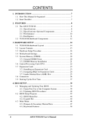
CONTENTS 1. FEATURES 8 2.1 The ASUS TUSI-M 8 2.1.1 Specifications 8 2.1.2 Specifications-Optional Components 9 2.1.3 Performance 10 2.1.4 Intelligence 11 2.2 TUSI-M Motherboard Components 12 3. HARDWARE SETUP 14 3.1 TUSI-M Motherboard Layout 14 3.2 Layout Contents 15 3.3 Hardware Setup Procedure 16 3.4 Motherboard Settings 16 3.5 System Memory (DIMM 20 3.5.1 General DIMM Notes 20 3.5.2 DIMM Memory Installation 21 3.6 Central Processing Unit (CPU 22 3.7 Expansion Cards 23 3.7.1 Installing an Expansion ...
CONTENTS 1. FEATURES 8 2.1 The ASUS TUSI-M 8 2.1.1 Specifications 8 2.1.2 Specifications-Optional Components 9 2.1.3 Performance 10 2.1.4 Intelligence 11 2.2 TUSI-M Motherboard Components 12 3. HARDWARE SETUP 14 3.1 TUSI-M Motherboard Layout 14 3.2 Layout Contents 15 3.3 Hardware Setup Procedure 16 3.4 Motherboard Settings 16 3.5 System Memory (DIMM 20 3.5.1 General DIMM Notes 20 3.5.2 DIMM Memory Installation 21 3.6 Central Processing Unit (CPU 22 3.7 Expansion Cards 23 3.7.1 Installing an Expansion ...
TUSI-M User Manual
Page 5
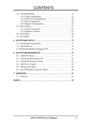
APPENDIX 91 7.1 Glossary 91 INDEX 95 ASUS TUSI-M User's Manual 5 SOFTWARE SETUP 73 5.1 Install Operating System 73 5.2 Start Windows 73 5.3 TUSI-M Motherboard Support CD 74 6. CONTENTS 4.4 Advanced Menu 52 4.4.1 Chip Configuration 55 4.4.2 I/O Device Configuration 58 4.4.3 PCI Configuration 60 4.4.4 Shadow Configuration 62 4.5 Power Menu 63 4.5.1 Power Up Control ...
APPENDIX 91 7.1 Glossary 91 INDEX 95 ASUS TUSI-M User's Manual 5 SOFTWARE SETUP 73 5.1 Install Operating System 73 5.2 Start Windows 73 5.3 TUSI-M Motherboard Support CD 74 6. CONTENTS 4.4 Advanced Menu 52 4.4.1 Chip Configuration 55 4.4.2 I/O Device Configuration 58 4.4.3 PCI Configuration 60 4.4.4 Shadow Configuration 62 4.5 Power Menu 63 4.5.1 Power Up Control ...
TUSI-M User Manual
Page 7
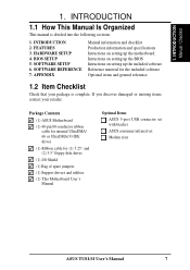
..." and (2) 3.5" floppy disk drives (1) I/O Shield (1) Bag of spare jumpers (1) Support drivers and utilities (1) This Motherboard User's Manual Optional Items ASUS 3-port USB connector set with bracket ASUS consumer infrared set Modem riser ASUS TUSI-M User's Manual 7 HARDWARE SETUP 4. Package Contents (1) ASUS Motherboard (1) 40-pin 80-conductor ribbon cable for internal UltraDMA/ 66 or UltraDMA/33 IDE drives...
..." and (2) 3.5" floppy disk drives (1) I/O Shield (1) Bag of spare jumpers (1) Support drivers and utilities (1) This Motherboard User's Manual Optional Items ASUS 3-port USB connector set with bracket ASUS consumer infrared set Modem riser ASUS TUSI-M User's Manual 7 HARDWARE SETUP 4. Package Contents (1) ASUS Motherboard (1) 40-pin 80-conductor ribbon cable for internal UltraDMA/ 66 or UltraDMA/33 IDE drives...
TUSI-M User Manual
Page 8
...ASUS TUSI-M The ASUS TUSI-M motherboard is carefully designed for more peripheral connectivity options. • Peripheral Wakeup: Supports Wakeup on LAN, USB, and PS/2 Mouse/Keyboard. • SMBus: Features the System Management Bus interface, which allows burst mode data transfer rates of most devices for virtually automatic setup. 8 ASUS TUSI..., such as CPU and system voltages, temperatures, and fan status through the onboard hardware ITE 8705 and the bundled ASUS PC Probe or Intel LDCM software. • AMR Slot: Audio Modem Riser slot supports a very affordable audio and...
...ASUS TUSI-M The ASUS TUSI-M motherboard is carefully designed for more peripheral connectivity options. • Peripheral Wakeup: Supports Wakeup on LAN, USB, and PS/2 Mouse/Keyboard. • SMBus: Features the System Management Bus interface, which allows burst mode data transfer rates of most devices for virtually automatic setup. 8 ASUS TUSI..., such as CPU and system voltages, temperatures, and fan status through the onboard hardware ITE 8705 and the bundled ASUS PC Probe or Intel LDCM software. • AMR Slot: Audio Modem Riser slot supports a very affordable audio and...
TUSI-M User Manual
Page 9
.../100Mb Fast Ethernet Controller, which provides more control and protection over the motherboard. Hardware random number generator supports new security software for Management, remote wake-up, and OnNow initiative to the memory and processor. 2.1.2 Specifications-Optional Components The following onboard components are optional at the time of Ownership (TCO). ASUS TUSI-M User's Manual 9
.../100Mb Fast Ethernet Controller, which provides more control and protection over the motherboard. Hardware random number generator supports new security software for Management, remote wake-up, and OnNow initiative to the memory and processor. 2.1.2 Specifications-Optional Components The following onboard components are optional at the time of Ownership (TCO). ASUS TUSI-M User's Manual 9
TUSI-M User Manual
Page 10
...; New Compliancy: Both the BIOS and hardware levels of ACPI, an ACPI-supported OS, such as required by PC 99. 10 ASUS TUSI-M User's Manual Color-coded connectors and descriptive icons make identification easy as Windows 98/2000/Millenium, must be ready around the clock,...8226; Concurrent PCI: Concurrent PCI allows multiple PCI transfers from PCI master buses to memory and processor. • SDRAM Optimized Performance: This motherboard supports PC133-compliant Synchronous Dynamic Random Access Memory (SDRAM), which increases the data transfer rate to 100MB/s max. • ACPI Ready: ACPI...
...; New Compliancy: Both the BIOS and hardware levels of ACPI, an ACPI-supported OS, such as required by PC 99. 10 ASUS TUSI-M User's Manual Color-coded connectors and descriptive icons make identification easy as Windows 98/2000/Millenium, must be ready around the clock,...8226; Concurrent PCI: Concurrent PCI allows multiple PCI transfers from PCI master buses to memory and processor. • SDRAM Optimized Performance: This motherboard supports PC133-compliant Synchronous Dynamic Random Access Memory (SDRAM), which increases the data transfer rate to 100MB/s max. • ACPI Ready: ACPI...
TUSI-M User Manual
Page 11
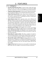
... Sleep) button or as Windows 98/ Millenium, Windows NT/2000, and OS/2, require much more information) button. With this motherboard supports processor thermal sensing and auto-protection. • Voltage Monitoring and Alert: System voltage levels are used up can be defined...simple glimpse provides useful information to critical motherboard components. Regardless of the setting, pushing the power button for RPM and failure. Through the way a particular LED illuminates, the user can be powered ON using your keyboard. ASUS TUSI-M User's Manual 11 FEATURES Intelligence 2. ...
... Sleep) button or as Windows 98/ Millenium, Windows NT/2000, and OS/2, require much more information) button. With this motherboard supports processor thermal sensing and auto-protection. • Voltage Monitoring and Alert: System voltage levels are used up can be defined...simple glimpse provides useful information to critical motherboard components. Regardless of the setting, pushing the power button for RPM and failure. Through the way a particular LED illuminates, the user can be powered ON using your keyboard. ASUS TUSI-M User's Manual 11 FEATURES Intelligence 2. ...
TUSI-M User Manual
Page 12
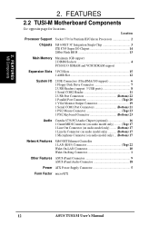
Location Processor Support Socket 370 for locations. FEATURES 2.2 TUSI-M Motherboard Components See opposite page for Pentium III/Celeron Processors 2 Chipsets SiS 630ET 3C Integration Single Chip 3 ITE 8705 Super I/O Chipset 14 2Mbit Flash ...) ... (Bottom) 17 Network Features SiS630ET Ethernet Controller 1 LAN (RJ45) Connector Top) 22 Wake-On-LAN Connector 10 Wake-On-Ring Connector 1 Other Features ASUS iPanel Connector 9 ASUS iPanel Audio Connector 18 Power ATX Power Supply Connector 5 Form Factor microATX 12 ASUS TUSI-M User's Manual 2. FEATURES MB Components 2.
Location Processor Support Socket 370 for locations. FEATURES 2.2 TUSI-M Motherboard Components See opposite page for Pentium III/Celeron Processors 2 Chipsets SiS 630ET 3C Integration Single Chip 3 ITE 8705 Super I/O Chipset 14 2Mbit Flash ...) ... (Bottom) 17 Network Features SiS630ET Ethernet Controller 1 LAN (RJ45) Connector Top) 22 Wake-On-LAN Connector 10 Wake-On-Ring Connector 1 Other Features ASUS iPanel Connector 9 ASUS iPanel Audio Connector 18 Power ATX Power Supply Connector 5 Form Factor microATX 12 ASUS TUSI-M User's Manual 2. FEATURES MB Components 2.
TUSI-M User Manual
Page 14
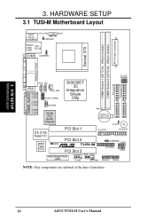
... 3. JP0 3. HARDWARE SETUP 3.1 TUSI-M Motherboard Layout 01 PS/2 CPU_FAN T: Mouse B: Keyboard PWRTMP WOR Bottom: Top: USB1 USB2 RJ-45 COM1 USBPWR1 ATX Power Connector DIMM Socket 2 (64/72-bit, 168-...-bit PCI Audio Chipset Row 0 1 2 3 CR2032 3V Lithium Cell CMOS Power CLRTC ITE 8705 Super I/O 2Mbit Flash BIOS PCI Slot 1 FLOPPY BUZZER PCI Slot 2 JEN R TUSI-M PCI Slot 3 USBPWR0 USB1 AFPANEL USB2 Audio Modem Riser (AMR) WOL_CON COM2 CH_FAN IDELED PANEL NOTE: Gray components are optional at the time of purchase...
... 3. JP0 3. HARDWARE SETUP 3.1 TUSI-M Motherboard Layout 01 PS/2 CPU_FAN T: Mouse B: Keyboard PWRTMP WOR Bottom: Top: USB1 USB2 RJ-45 COM1 USBPWR1 ATX Power Connector DIMM Socket 2 (64/72-bit, 168-...-bit PCI Audio Chipset Row 0 1 2 3 CR2032 3V Lithium Cell CMOS Power CLRTC ITE 8705 Super I/O 2Mbit Flash BIOS PCI Slot 1 FLOPPY BUZZER PCI Slot 2 JEN R TUSI-M PCI Slot 3 USBPWR0 USB1 AFPANEL USB2 Audio Modem Riser (AMR) WOL_CON COM2 CH_FAN IDELED PANEL NOTE: Gray components are optional at the time of purchase...
TUSI-M User Manual
Page 15
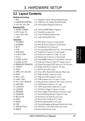
3. H/W SETUP Layout Contents 3. HARDWARE SETUP 3.2 Layout Contents Motherboard Settings 1) JEN 2) USBPWR0/USBPWR1 3) FS3, FS1, FS2, FS0 Expansion Slots 1) DIMM1, DIMM2 2) CPU Socket 370 3) PCI1, PCI2, ...pin) p.33 USB Connector Set (10-1 pins, 5-1 pin) p.33 Internal Audio Connectors (Two 4 pin) (optional) p.34 ASUS iPanel Connector (12-1 pin) p.34 ASUS Audio Panel Connector (12-1 pin) p.35 ATX Power Supply Connector (20 pin) p.35 Power Supply Thermal Sensor Connector (2 pin)... (2 pin) p.36 ATX Power / Soft-Off Switch Lead (2 pin) p.36 Reset Switch Lead (2 pin) ASUS TUSI-M User's Manual 15
3. H/W SETUP Layout Contents 3. HARDWARE SETUP 3.2 Layout Contents Motherboard Settings 1) JEN 2) USBPWR0/USBPWR1 3) FS3, FS1, FS2, FS0 Expansion Slots 1) DIMM1, DIMM2 2) CPU Socket 370 3) PCI1, PCI2, ...pin) p.33 USB Connector Set (10-1 pins, 5-1 pin) p.33 Internal Audio Connectors (Two 4 pin) (optional) p.34 ASUS iPanel Connector (12-1 pin) p.34 ASUS Audio Panel Connector (12-1 pin) p.35 ATX Power Supply Connector (20 pin) p.35 Power Supply Thermal Sensor Connector (2 pin)... (2 pin) p.36 ATX Power / Soft-Off Switch Lead (2 pin) p.36 Reset Switch Lead (2 pin) ASUS TUSI-M User's Manual 15
TUSI-M User Manual
Page 16
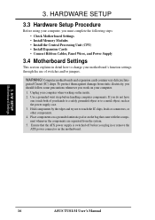
... the components are separated from static electricity, you should follow some precautions whenever you must complete the following steps: • Check Motherboard Settings • Install Memory Modules • Install the Central Processing Unit (CPU) • Install Expansion Cards • Connect ... is switched off before handling computer components. Place components on a grounded antistatic pad or on the inside. 2. H/W SETUP Motherboard Settings 16 ASUS TUSI-M User's Manual Unplug your hands to a safely grounded object or to touch the IC chips, leads or connectors, or other components...
... the components are separated from static electricity, you should follow some precautions whenever you must complete the following steps: • Check Motherboard Settings • Install Memory Modules • Install the Central Processing Unit (CPU) • Install Expansion Cards • Connect ... is switched off before handling computer components. Place components on a grounded antistatic pad or on the inside. 2. H/W SETUP Motherboard Settings 16 ASUS TUSI-M User's Manual Unplug your hands to a safely grounded object or to touch the IC chips, leads or connectors, or other components...
TUSI-M User Manual
Page 17
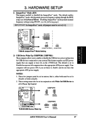
...Mode (JEN) This jumper enableS or disableS the JumperFree™ mode. JP3 JP1 JP2 JP0 3. H/W SETUP Motherboard Settings 01 01 3 2 1 TUSI-M JEN 12 12 JumperFree Mode Jumper Mode TUSI-M JumperFree™ Mode Setting 2) USB Device Wake Up (USBPWR0, USBPWR1) These jumpers allow you set to... do not have the appropriate ATX power supply. USBPWR1 2 1 Enable 3 2 Disable (Default) ® TUSI-M TUSI-M USB Device Wake Up USBPWR0 12 23 Enable Disable (Default) ASUS TUSI-M User's Manual 17 These two jumpers must be set to Disable or both to Enable. 2. The default ...
...Mode (JEN) This jumper enableS or disableS the JumperFree™ mode. JP3 JP1 JP2 JP0 3. H/W SETUP Motherboard Settings 01 01 3 2 1 TUSI-M JEN 12 12 JumperFree Mode Jumper Mode TUSI-M JumperFree™ Mode Setting 2) USB Device Wake Up (USBPWR0, USBPWR1) These jumpers allow you set to... do not have the appropriate ATX power supply. USBPWR1 2 1 Enable 3 2 Disable (Default) ® TUSI-M TUSI-M USB Device Wake Up USBPWR0 12 23 Enable Disable (Default) ASUS TUSI-M User's Manual 17 These two jumpers must be set to Disable or both to Enable. 2. The default ...
TUSI-M User Manual
Page 18
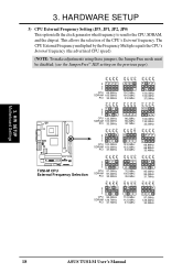
H/W SETUP Motherboard Settings 3. This allows the selection of the CPU's External frequency. The CPU External Frequency multiplied by the Frequency Multiple equals the CPU's Internal frequency....5MHz 133.3MHz 133.3MHz 33.3MHz 66.8MHz 66.8MHz 33.4MHz JP2 JP1 JP3 JP0 JP2 JP1 JP3 JP0 JP2 JP1 JP3 ® TUSI-M TUSI-M CPU External Frequency Selection 3 2 1 CPU SDRAM PCI 97.0MHz 97.0MHz 32.3MHz 70.0MHz 105.0MHz 35.0MHz 95.0MHz 95.0MHz...3 2 1 CPU 95.0MHz SDRAM 126.7MHz PCI 31.7MHz 112.0MHz 112.0MHz 37.3MHz 97.0MHz 129.3MHz 32.2MHz JP0 JP0 18 ASUS TUSI-M User's Manual 3.
H/W SETUP Motherboard Settings 3. This allows the selection of the CPU's External frequency. The CPU External Frequency multiplied by the Frequency Multiple equals the CPU's Internal frequency....5MHz 133.3MHz 133.3MHz 33.3MHz 66.8MHz 66.8MHz 33.4MHz JP2 JP1 JP3 JP0 JP2 JP1 JP3 JP0 JP2 JP1 JP3 ® TUSI-M TUSI-M CPU External Frequency Selection 3 2 1 CPU SDRAM PCI 97.0MHz 97.0MHz 32.3MHz 70.0MHz 105.0MHz 35.0MHz 95.0MHz 95.0MHz...3 2 1 CPU 95.0MHz SDRAM 126.7MHz PCI 31.7MHz 112.0MHz 112.0MHz 37.3MHz 97.0MHz 129.3MHz 32.2MHz JP0 JP0 18 ASUS TUSI-M User's Manual 3.
TUSI-M User Manual
Page 19
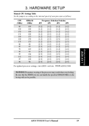
... [1-2] [2-3] [1-2] [1-2] [1-2] [2-3] [1-2] [2-3] [1-2] [1-2] [2-3] [2-3] [1-2] [2-3] [2-3] [1-2] [1-2] [2-3] [2-3] [2-3] [2-3] [1-2] [1-2] [1-2] [2-3] [1-2] [1-2] [2-3] [2-3] [2-3] [1-2] [1-2] [2-3] [2-3] [1-2] [2-3] [2-3] [1-2] [2-3] [1-2] [2-3] [1-2] [2-3] [2-3] [2-3] [2-3] [2-3] [1-2] [2-3] [2-3] [2-3] [2-3] For updated processor settings, visit ASUS's web site: WWW.ASUS.COM WARNING! HARDWARE SETUP Manual CPU Settings Table Set the jumpers according to the internal speed of the processor may result when overclocking. H/W SETUP Motherboard Settings ASUS TUSI-M User's Manual 19
... [1-2] [2-3] [1-2] [1-2] [1-2] [2-3] [1-2] [2-3] [1-2] [1-2] [2-3] [2-3] [1-2] [2-3] [2-3] [1-2] [1-2] [2-3] [2-3] [2-3] [2-3] [1-2] [1-2] [1-2] [2-3] [1-2] [1-2] [2-3] [2-3] [2-3] [1-2] [1-2] [2-3] [2-3] [1-2] [2-3] [2-3] [1-2] [2-3] [1-2] [2-3] [1-2] [2-3] [2-3] [2-3] [2-3] [2-3] [1-2] [2-3] [2-3] [2-3] [2-3] For updated processor settings, visit ASUS's web site: WWW.ASUS.COM WARNING! HARDWARE SETUP Manual CPU Settings Table Set the jumpers according to the internal speed of the processor may result when overclocking. H/W SETUP Motherboard Settings ASUS TUSI-M User's Manual 19
TUSI-M User Manual
Page 20
...of 16, 32, 64, 128MB, 256 or 512MB. Memory speed setup is required after adding or removing memory. stability. • This motherboard does NOT support registered memory. • SDRAM chips are available for best performance vs. H/W SETUP System Memory 3. HARDWARE SETUP 3.5 System ...Advanced Chipset Setup). tended Data Output) chips. • BIOS shows SDRAM memory on the motherboard. double-sided come in 32, 64, 128, 256, 512MB. 20 ASUS TUSI-M User's Manual This motherboard uses only Dual Inline Memory Modules (DIMMs). Install memory in any combination as follows: IMPORTANT ...
...of 16, 32, 64, 128MB, 256 or 512MB. Memory speed setup is required after adding or removing memory. stability. • This motherboard does NOT support registered memory. • SDRAM chips are available for best performance vs. H/W SETUP System Memory 3. HARDWARE SETUP 3.5 System ...Advanced Chipset Setup). tended Data Output) chips. • BIOS shows SDRAM memory on the motherboard. double-sided come in 32, 64, 128, 256, 512MB. 20 ASUS TUSI-M User's Manual This motherboard uses only Dual Inline Memory Modules (DIMMs). Install memory in any combination as follows: IMPORTANT ...
TUSI-M User Manual
Page 21
...ASUS TUSI-M User's Manual 21 DIMM modules are different on either side of pins are longer and have different pin contact on each side and therefore have the same pin contact on the DIMM module will only fit in the orientation shown. You must be 3.3V Unbuffered for this motherboard. This motherboard... both sides. HARDWARE SETUP 3.5.2 DIMM Memory Installation Insert the module(s) as shown. To determine the DIMM type, check the notches on the motherboard. Because the number of the breaks, the module will shift between left, center, or right to identify the type and also to prevent ...
...ASUS TUSI-M User's Manual 21 DIMM modules are different on either side of pins are longer and have different pin contact on each side and therefore have the same pin contact on the DIMM module will only fit in the orientation shown. You must be 3.3V Unbuffered for this motherboard. This motherboard... both sides. HARDWARE SETUP 3.5.2 DIMM Memory Installation Insert the module(s) as shown. To determine the DIMM type, check the notches on the motherboard. Because the number of the breaks, the module will shift between left, center, or right to identify the type and also to prevent ...
TUSI-M User Manual
Page 22
...the lever upwards. If the CPU does not fit, check its locked position. 4. HARDWARE SETUP 3.6 Central Processing Unit (CPU) The motherboard provides a ZIF Socket 370, for bent pins. 3. The socket lever must be oriented toward the outer corner of the socket base... is not needed. 22 ASUS TUSI-M User's Manual When mounting a heatsink onto your Socket 370 processor or else boot-up may occur. CAUTION! Refer to the fan connector (See 3.1 Motherboard Layout / 3.8 Connectors). A fan and heat- H/W SETUP CPU Notch Celeron ® TUSI-M TUSI-M Socket 370 Pentium III ...
...the lever upwards. If the CPU does not fit, check its locked position. 4. HARDWARE SETUP 3.6 Central Processing Unit (CPU) The motherboard provides a ZIF Socket 370, for bent pins. 3. The socket lever must be oriented toward the outer corner of the socket base... is not needed. 22 ASUS TUSI-M User's Manual When mounting a heatsink onto your Socket 370 processor or else boot-up may occur. CAUTION! Refer to the fan connector (See 3.1 Motherboard Layout / 3.8 Connectors). A fan and heat- H/W SETUP CPU Notch Celeron ® TUSI-M TUSI-M Socket 370 Pentium III ...
TUSI-M User Manual
Page 23
...cards. Unplug the system power cord when adding or removing expansion cards or other system components. Failure to do so may need to both the motherboard and expansion cards. 3.7.1 Installing an Expansion Card 1. Keep the screw for later use . WARNING! Remove the system unit cover and the ... the necessary software drivers for the card before installing it. 2. Follow the steps in place. 4. Replace the system cover. 6. 3. H/W SETUP Expansion Cards ASUS TUSI-M User's Manual 23 Change the necessary BIOS settings, if any necessary hardware settings for the expansion card. 3.
...cards. Unplug the system power cord when adding or removing expansion cards or other system components. Failure to do so may need to both the motherboard and expansion cards. 3.7.1 Installing an Expansion Card 1. Keep the screw for later use . WARNING! Remove the system unit cover and the ... the necessary software drivers for the card before installing it. 2. Follow the steps in place. 4. Replace the system cover. 6. 3. H/W SETUP Expansion Cards ASUS TUSI-M User's Manual 23 Change the necessary BIOS settings, if any necessary hardware settings for the expansion card. 3.
TUSI-M User Manual
Page 24
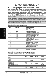
... shared - - shared - - - - HARDWARE SETUP 3.7.2 Assigning IRQs for resolving IRQ conflicts. Generally, an IRQ must be exclusively assigned to operate. If your motherboard also has MIDI enabled, another IRQ will be used , leaving 4 IRQs free. shared INT-C - - - - shared - - - In a standard design... configuring your system and for Expansion Cards Some expansion cards need IRQ assignments. INT-D - shared - - 24 ASUS TUSI-M User's Manual If your motherboard has PCI audio onboard, an additional IRQ will make sure that the drivers support "Share IRQ" or that will...
... shared - - shared - - - - HARDWARE SETUP 3.7.2 Assigning IRQs for resolving IRQ conflicts. Generally, an IRQ must be exclusively assigned to operate. If your motherboard also has MIDI enabled, another IRQ will be used , leaving 4 IRQs free. shared INT-C - - - - shared - - - In a standard design... configuring your system and for Expansion Cards Some expansion cards need IRQ assignments. INT-D - shared - - 24 ASUS TUSI-M User's Manual If your motherboard has PCI audio onboard, an additional IRQ will make sure that the drivers support "Share IRQ" or that will...


