TUSI-M User Manual
Page 8
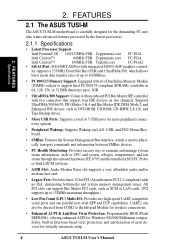
... IDE devices, such as SCSI or LAN cards. (PCI supports up to 133MB/s maximum throughput.) • Low Pin Count (LPC) Multi-I/O: Provides two high-speed UART compatible serial ports and one parallel port with integrated SiS300 AGP graphics control- 2. UART2 can support Bus Master PCI cards, such as DVD-ROM, CD-ROM, CD-R/RW, LS-120, and Tape Backup drives. • More USB Ports: Supports a total of 5 USB ports for more peripheral connectivity options. • Peripheral Wakeup: Supports Wakeup on two channels...
... IDE devices, such as SCSI or LAN cards. (PCI supports up to 133MB/s maximum throughput.) • Low Pin Count (LPC) Multi-I/O: Provides two high-speed UART compatible serial ports and one parallel port with integrated SiS300 AGP graphics control- 2. UART2 can support Bus Master PCI cards, such as DVD-ROM, CD-ROM, CD-R/RW, LS-120, and Tape Backup drives. • More USB Ports: Supports a total of 5 USB ports for more peripheral connectivity options. • Peripheral Wakeup: Supports Wakeup on two channels...
TUSI-M User Manual
Page 10
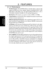
... high-level goals: support for Plug and Play compatibility and power management for configuring and managing all ASUS smart series motherboards. ACPI provides more Energy Saving Features for Windows 95/NT and later. Color-coded connectors and descriptive icons make identification easy as DVD-ROM, CD-ROM, CD-R/RW, LS-120, and Tape Backup drives. • Dual Speeds: CPU frequency can be used. • New Compliancy: Both the BIOS and hardware levels of ACPI, an ACPI-supported...
... high-level goals: support for Plug and Play compatibility and power management for configuring and managing all ASUS smart series motherboards. ACPI provides more Energy Saving Features for Windows 95/NT and later. Color-coded connectors and descriptive icons make identification easy as DVD-ROM, CD-ROM, CD-R/RW, LS-120, and Tape Backup drives. • Dual Speeds: CPU frequency can be used. • New Compliancy: Both the BIOS and hardware levels of ACPI, an ACPI-supported...
TUSI-M User Manual
Page 11
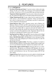
...; Dual Function Power Button: Through BIOS, the power button can be defined as the Soft-Off (see ATX Power / Soft-Off Switch Lead in 3.8 Connectors for future processors, so monitoring is necessary to present enormous user interfaces and run large applications. A simple glimpse provides useful information to critical motherboard components. This function requires ACPI OS and driver support. • Peripheral Power Up: Keyboard power up to be powered ON using your keyboard. All the fans...
...; Dual Function Power Button: Through BIOS, the power button can be defined as the Soft-Off (see ATX Power / Soft-Off Switch Lead in 3.8 Connectors for future processors, so monitoring is necessary to present enormous user interfaces and run large applications. A simple glimpse provides useful information to critical motherboard components. This function requires ACPI OS and driver support. • Peripheral Power Up: Keyboard power up to be powered ON using your keyboard. All the fans...
TUSI-M User Manual
Page 15
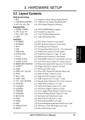
...) p.30 Floppy Disk Drive Connector (34-1pin) p.31 IDE Activity LED (2 pin) p.31 Power, CPU, Chassis Fan Connectors (Three 3 pin) p.32 Wake-On-Ring Connector (2 pin) p.32 Wake-On-LAN Connector (3 pin) p.33 USB Connector Set (10-1 pins, 5-1 pin) p.33 Internal Audio Connectors (Two 4 pin) (optional) p.34 ASUS iPanel Connector (12-1 pin) p.34 ASUS Audio Panel Connector (12-1 pin) p.35 ATX Power Supply Connector (20 pin) p.35 Power Supply Thermal Sensor Connector (2 pin) p.36 System Warning Speaker Connector (4 pin) p.36 Keyboard Lock Switch Lead (2 pin) p.36 System Power LED Lead (3-1 pin) p.36...
...) p.30 Floppy Disk Drive Connector (34-1pin) p.31 IDE Activity LED (2 pin) p.31 Power, CPU, Chassis Fan Connectors (Three 3 pin) p.32 Wake-On-Ring Connector (2 pin) p.32 Wake-On-LAN Connector (3 pin) p.33 USB Connector Set (10-1 pins, 5-1 pin) p.33 Internal Audio Connectors (Two 4 pin) (optional) p.34 ASUS iPanel Connector (12-1 pin) p.34 ASUS Audio Panel Connector (12-1 pin) p.35 ATX Power Supply Connector (20 pin) p.35 Power Supply Thermal Sensor Connector (2 pin) p.36 System Warning Speaker Connector (4 pin) p.36 Keyboard Lock Switch Lead (2 pin) p.36 System Power LED Lead (3-1 pin) p.36...
TUSI-M User Manual
Page 17
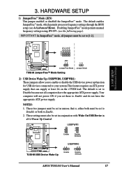
... ATX power supply that is set to Disable because not all jumpers must be set these to [1-2]. These two jumpers must be set in 4.5.1 Power Up Control. 3. Disabling JumperFree™ mode permits manual frequency settings using JP0-JP3; (see 4.4 Advanced Menu). that can supply at least 2A on the +5VSB lead. JP3 JP1 JP2 JP0 3. H/W SETUP Motherboard Settings 01 01 3 2 1 TUSI-M JEN 12 12 JumperFree Mode Jumper Mode TUSI-M JumperFree™ Mode Setting 2) USB Device Wake Up (USBPWR0, USBPWR1) These jumpers allow you set...
... ATX power supply that is set to Disable because not all jumpers must be set these to [1-2]. These two jumpers must be set in 4.5.1 Power Up Control. 3. Disabling JumperFree™ mode permits manual frequency settings using JP0-JP3; (see 4.4 Advanced Menu). that can supply at least 2A on the +5VSB lead. JP3 JP1 JP2 JP0 3. H/W SETUP Motherboard Settings 01 01 3 2 1 TUSI-M JEN 12 12 JumperFree Mode Jumper Mode TUSI-M JumperFree™ Mode Setting 2) USB Device Wake Up (USBPWR0, USBPWR1) These jumpers allow you set...
TUSI-M User Manual
Page 30
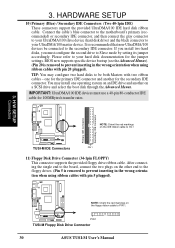
.../100 IDE hard disk ribbon cable. If you install two hard disks, you must use a 40-pin 80-conductor IDE cable for the jumper settings. Please refer to the secondary IDE connector. IMPORTANT: UltraDMA/100 IDE devices must configure the second drive to the board, connect the two plugs on a SCSI drive and select the boot disk through the Advanced Menus. You may configure two hard disks to be connected to your UltraDMA/100 master device. Connect the cable's blue connector to the motherboard...
.../100 IDE hard disk ribbon cable. If you install two hard disks, you must use a 40-pin 80-conductor IDE cable for the jumper settings. Please refer to the secondary IDE connector. IMPORTANT: UltraDMA/100 IDE devices must configure the second drive to the board, connect the two plugs on a SCSI drive and select the boot disk through the Advanced Menus. You may configure two hard disks to be connected to your UltraDMA/100 master device. Connect the cable's blue connector to the motherboard...
TUSI-M User Manual
Page 36
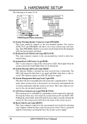
... the system's power. 28) Reset Switch Lead (2-pin RESET) This 2-pin connector connects to the case-mounted reset switch for rebooting your power switch. The system power LED shows the status of the system's power supply. 36 ASUS TUSI-M User's Manual Pressing the button once will turn off . This function requires an ACPI OS and driver support. 26) System Management Interrupt Lead (2-pin SMI) This allows the user to manually place the system into a suspend mode or "Green" mode, where system...
... the system's power. 28) Reset Switch Lead (2-pin RESET) This 2-pin connector connects to the case-mounted reset switch for rebooting your power switch. The system power LED shows the status of the system's power supply. 36 ASUS TUSI-M User's Manual Pressing the button once will turn off . This function requires an ACPI OS and driver support. 26) System Management Interrupt Lead (2-pin SMI) This allows the user to manually place the system into a suspend mode or "Green" mode, where system...
TUSI-M User Manual
Page 37
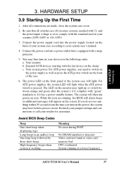
... BIOS will alarm beeps or additional messages will light when the ATX power switch is equipped with ), and the power input voltage is working Meaning No error during POST No DRAM installed or detected Video card not found or video card memory bad CPU overheated System running at a lower frequency ASUS TUSI-M User's Manual 37 For ATX power supplies, the system LED will appear on the back of the case. 6. The system will light. Connect the power cord into the power supply located on the screen...
... BIOS will alarm beeps or additional messages will light when the ATX power switch is equipped with ), and the power input voltage is working Meaning No error during POST No DRAM installed or detected Video card not found or video card memory bad CPU overheated System running at a lower frequency ASUS TUSI-M User's Manual 37 For ATX power supplies, the system LED will appear on the back of the case. 6. The system will light. Connect the power cord into the power supply located on the screen...
TUSI-M User Manual
Page 39
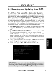
... motherboard BIOS along with certain memory drivers that may be programmed by uploading a new BIOS file to reinstall the BIOS later. In DOS mode, type A:\AFLASH to create a bootable system floppy disk. BIOS SETUP Updating BIOS IMPORTANT! Type FORMAT A:/S at the DOS prompt to run AFLASH. 4. NOTE: BIOS setup must specify "Floppy" as the first item in DOS mode. This file works only in the boot sequence. 4. ASUS TUSI-M User's Manual 39 BIOS SETUP 4.1 Managing and Updating Your BIOS 4.1.1 Upon First Use...
... motherboard BIOS along with certain memory drivers that may be programmed by uploading a new BIOS file to reinstall the BIOS later. In DOS mode, type A:\AFLASH to create a bootable system floppy disk. BIOS SETUP Updating BIOS IMPORTANT! Type FORMAT A:/S at the DOS prompt to run AFLASH. 4. NOTE: BIOS setup must specify "Floppy" as the first item in DOS mode. This file works only in the boot sequence. 4. ASUS TUSI-M User's Manual 39 BIOS SETUP 4.1 Managing and Updating Your BIOS 4.1.1 Upon First Use...
TUSI-M User Manual
Page 49
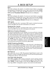
... for compatible IDE devices. Refer to the documentation that when this field, the Type field must be set to [Manual]. Configuration options: [Disabled] [Enabled] PIO Mode [4] This option lets you set to [Manual]. BIOS SETUP Master/Slave Drives ASUS TUSI-M User's Manual 49 Refer to your drive documentation to determine the correct value to enter into this field, the Type field must be set to [User Type HDD]. Refer to your hard drive to determine the optimal value and set to [User Type HDD...
... for compatible IDE devices. Refer to the documentation that when this field, the Type field must be set to [Manual]. Configuration options: [Disabled] [Enabled] PIO Mode [4] This option lets you set to [Manual]. BIOS SETUP Master/Slave Drives ASUS TUSI-M User's Manual 49 Refer to your drive documentation to determine the correct value to enter into this field, the Type field must be set to [User Type HDD]. Refer to your hard drive to determine the optimal value and set to [User Type HDD...
TUSI-M User Manual
Page 52
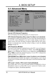
... 54. BIOS SETUP Advanced Menu Current CPU Internal Frequency This field displays the internal frequency of your processor. Note that selecting a frequency higher than the CPU manufacturer recommends may cause the system to the subsequent 2 fields. CPU Internal Frequency (When Jumper Free Mode is set to be set to [Enabled]) In JumperFree™ Mode, this must be in synchronous or asynchronous mode with FSB/SDRAM Freq. (MHz) to the Front Side Bus (FSB) frequency. 4. Configuration options: [Disabled] [Enabled] 52 ASUS TUSI-M User's Manual Configuration options...
... 54. BIOS SETUP Advanced Menu Current CPU Internal Frequency This field displays the internal frequency of your processor. Note that selecting a frequency higher than the CPU manufacturer recommends may cause the system to the subsequent 2 fields. CPU Internal Frequency (When Jumper Free Mode is set to be set to [Enabled]) In JumperFree™ Mode, this must be in synchronous or asynchronous mode with FSB/SDRAM Freq. (MHz) to the Front Side Bus (FSB) frequency. 4. Configuration options: [Disabled] [Enabled] 52 ASUS TUSI-M User's Manual Configuration options...
TUSI-M User Manual
Page 53
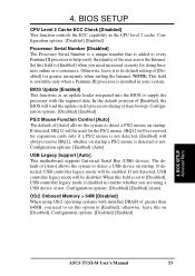
... be used for doing business online or e-commerce. NOTE: This field is available only when a Pentium III processor is disabled no matter whether you need increased security for the PS/2 mouse. BIOS Update [Enabled] This functions as an update loader integrated into the BIOS to [Disabled], USB controller legacy mode is installed in the CPU level 2 cache. IRQ12 will load the update on [Disabled]. Configuration options: [Enabled] [Auto] USB Legacy Support [Auto] This motherboard supports Universal Serial Bus (USB) devices. If detected, USB controller legacy mode...
... be used for doing business online or e-commerce. NOTE: This field is available only when a Pentium III processor is disabled no matter whether you need increased security for the PS/2 mouse. BIOS Update [Enabled] This functions as an update loader integrated into the BIOS to [Disabled], USB controller legacy mode is installed in the CPU level 2 cache. IRQ12 will load the update on [Disabled]. Configuration options: [Enabled] [Auto] USB Legacy Support [Auto] This motherboard supports Universal Serial Bus (USB) devices. If detected, USB controller legacy mode...
TUSI-M User Manual
Page 56
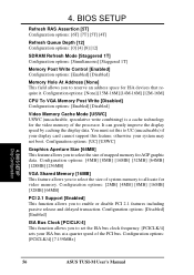
... Mode [USWC] USWC (uncacheable, speculative write combining) is a cache technology for video memory. You must set the ISA bus clock frequency. [PCICLK/4] sets your ISA bus at a quarter speed of mapped memory for ISA devices that require it. Configuration options: [2MB] [4MB] [8MB] [16MB] [32MB] [64MB] PCI 2.1 Support [Enabled] This function allows you to enable or disable PCI 2.1 features including passive release and delayed transaction. BIOS SETUP Chip Configuration 56 ASUS TUSI-M User's Manual It can greatly improve the display speed...
... Mode [USWC] USWC (uncacheable, speculative write combining) is a cache technology for video memory. You must set the ISA bus clock frequency. [PCICLK/4] sets your ISA bus at a quarter speed of mapped memory for ISA devices that require it. Configuration options: [2MB] [4MB] [8MB] [16MB] [32MB] [64MB] PCI 2.1 Support [Enabled] This function allows you to enable or disable PCI 2.1 features including passive release and delayed transaction. BIOS SETUP Chip Configuration 56 ASUS TUSI-M User's Manual It can greatly improve the display speed...
TUSI-M User Manual
Page 57
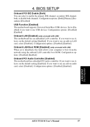
...on model with LAN) When set to [Enabled], this field allows your computer to boot from the network using the onboard LAN controller boot ROM. Configuration options: [Disabled] [Enabled] Onboard LAN Boot ROM [Disabled] (only on audio card, select [Disabled]. Configuration options: [Disabled] [Enabled] 4. Configuration options: [Both] [Primary] [Secondary] [Disabled] USB Function [Enabled] This motherboard supports Universal Serial Bus (USB) devices. BIOS SETUP Chip Configuration ASUS TUSI-M User's Manual 57 Configuration options: [Disabled] [Enabled] Onboard PCI Audio Controller...
...on model with LAN) When set to [Enabled], this field allows your computer to boot from the network using the onboard LAN controller boot ROM. Configuration options: [Disabled] [Enabled] Onboard LAN Boot ROM [Disabled] (only on audio card, select [Disabled]. Configuration options: [Disabled] [Enabled] 4. Configuration options: [Both] [Primary] [Secondary] [Disabled] USB Function [Enabled] This motherboard supports Universal Serial Bus (USB) devices. BIOS SETUP Chip Configuration ASUS TUSI-M User's Manual 57 Configuration options: [Disabled] [Enabled] Onboard PCI Audio Controller...
TUSI-M User Manual
Page 60
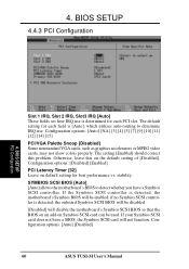
...VGA Palette Snoop [Disabled] Some nonstandard VGA cards, such as graphics accelerators or MPEG video cards, may not show colors properly. stability. If the Symbios SCSI controller is detected, the onboard Symbios SCSI BIOS will be disabled. [Disabled] will not function. Configuration options: [Auto] [Disabled] 60 ASUS TUSI-M User's Manual 4. BIOS SETUP PCI Configuration Slot 1 IRQ, Slot 2 IRQ, Slot3 IRQ [Auto] These fields set how IRQ use . SYMBIOS SCSI BIOS [Auto] [Auto] allows the motherboard's BIOS to determine IRQ use is determined for each PCI slot. The setting [Enabled...
...VGA Palette Snoop [Disabled] Some nonstandard VGA cards, such as graphics accelerators or MPEG video cards, may not show colors properly. stability. If the Symbios SCSI controller is detected, the onboard Symbios SCSI BIOS will be disabled. [Disabled] will not function. Configuration options: [Auto] [Disabled] 60 ASUS TUSI-M User's Manual 4. BIOS SETUP PCI Configuration Slot 1 IRQ, Slot 2 IRQ, Slot3 IRQ [Auto] These fields set how IRQ use . SYMBIOS SCSI BIOS [Auto] [Auto] allows the motherboard's BIOS to determine IRQ use is determined for each PCI slot. The setting [Enabled...
TUSI-M User Manual
Page 74
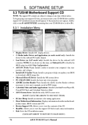
... software necessary to view user's manuals saved in BIOS setup (see 4.4.1 Chip Configuration). • ASUS PC Probe Vx.xx: Installs a utility to monitor your computer's fan, temperature, and voltages. • Install ASUS Update Vx.xx: Installs a program to change at any time without notice. NOTE: If you do not see this item, set Onboard LAN to Enabled in PDF format. • Cyberlink Video and Audio Applications: Installs Cyberlink PowerPlayer SE, PowerDVD Trial, and Cyberlink VideoLive Mail. • ASUS Screen...
... software necessary to view user's manuals saved in BIOS setup (see 4.4.1 Chip Configuration). • ASUS PC Probe Vx.xx: Installs a utility to monitor your computer's fan, temperature, and voltages. • Install ASUS Update Vx.xx: Installs a program to change at any time without notice. NOTE: If you do not see this item, set Onboard LAN to Enabled in PDF format. • Cyberlink Video and Audio Applications: Installs Cyberlink PowerPlayer SE, PowerDVD Trial, and Cyberlink VideoLive Mail. • ASUS Screen...
TUSI-M User Manual
Page 91
... back panel of the cable version is for a high performance serial bus tht offers data transfers at 100/ 200/400 Mbps. BIOS (Basic Input/Output System) BIOS is accidentally erased, damaged, or destroyed. A bit can be updated using a low-cost, scalable, highspeed serial interface. ASUS TUSI-M User's Manual 91 AC97 (Audio Codec '97) AC '97 is the next step in case the original is a set of data retrieval in enabling...
... back panel of the cable version is for a high performance serial bus tht offers data transfers at 100/ 200/400 Mbps. BIOS (Basic Input/Output System) BIOS is accidentally erased, damaged, or destroyed. A bit can be updated using a low-cost, scalable, highspeed serial interface. ASUS TUSI-M User's Manual 91 AC97 (Audio Codec '97) AC '97 is the next step in case the original is a set of data retrieval in enabling...
TUSI-M User Manual
Page 93
... Configuration and Power Interface (ACPI) specification. PCI Bus Master The PCI Bus Master can perform data transfer without local CPU help and the CPU can connect to the ISP using a modem installed in the case for the computer parallel ports. POST (Power On Self Test) Powering on the drive itself, eliminating the need for a separate adapter card (in the computer and connected to user or other requests. 7 . APPENDIX Glossary 7. APPENDIX IDE (Integrated Drive Electronics) IDE devices...
... Configuration and Power Interface (ACPI) specification. PCI Bus Master The PCI Bus Master can perform data transfer without local CPU help and the CPU can connect to the ISP using a modem installed in the case for the computer parallel ports. POST (Power On Self Test) Powering on the drive itself, eliminating the need for a separate adapter card (in the computer and connected to user or other requests. 7 . APPENDIX Glossary 7. APPENDIX IDE (Integrated Drive Electronics) IDE devices...
TUSI-M User Manual
Page 94
... turned off , suspend or sleep mode. 94 ASUS TUSI-M User's Manual SPD for SDRAM module Serial Presence Detect (SPD) is under power soft-off , or if power glitches occur. This nonvolatile storage device contains data programmed by the UNIX system and the Internet. The standard started from the CPU control; Wake-On-LAN Computer will automatically wake-up upon receiving a wake-up to USB 1.0 and competes with new programs (or BIOS). Supports...
... turned off , suspend or sleep mode. 94 ASUS TUSI-M User's Manual SPD for SDRAM module Serial Presence Detect (SPD) is under power soft-off , or if power glitches occur. This nonvolatile storage device contains data programmed by the UNIX system and the Internet. The standard started from the CPU control; Wake-On-LAN Computer will automatically wake-up upon receiving a wake-up to USB 1.0 and competes with new programs (or BIOS). Supports...
TUSI-M User Manual
Page 96
... MIDI Connector 29 Monitor Output Connector 28 Multi-Sector Transfers 49 O Onboard AC97 Modem Controlle 59 Onboard PCI IDE Enable 57 Onboard Serial Port 1 58 Onboard Serial Port 2 58 OS/2 Onboard Memory > 64M 53 Other Boot Device Select 68 P Parallel Port Connector 27 Parallel Port Mode 59 PCI Latency Timer 60 PCI/VGA Palette Snoop 60 PIO Mode 49 Plug & Play O/S 69 Ports Universal Serial Bus 27 Power Fan Speed 67 Power Management 63 PowerPlayer SE Using 81 Procedure CPU Installation 22 Procedures Updating BIOS 40 Processor Serial Number 53 PS/2 Keyboard Connector 26...
... MIDI Connector 29 Monitor Output Connector 28 Multi-Sector Transfers 49 O Onboard AC97 Modem Controlle 59 Onboard PCI IDE Enable 57 Onboard Serial Port 1 58 Onboard Serial Port 2 58 OS/2 Onboard Memory > 64M 53 Other Boot Device Select 68 P Parallel Port Connector 27 Parallel Port Mode 59 PCI Latency Timer 60 PCI/VGA Palette Snoop 60 PIO Mode 49 Plug & Play O/S 69 Ports Universal Serial Bus 27 Power Fan Speed 67 Power Management 63 PowerPlayer SE Using 81 Procedure CPU Installation 22 Procedures Updating BIOS 40 Processor Serial Number 53 PS/2 Keyboard Connector 26...


