TUSI-M User Manual
Page 2
... product design represented by the digit before and after the period of the manual revision number. All Rights Reserved. Product Name: ASUS TUSI-M Manual Revision: 1.00 E894B Release Date: October 2001 2 ASUS TUSI-M User's Manual USER'S NOTICE No part of this manual may or may be extended if: (1) the product is a registered trademark of...
... product design represented by the digit before and after the period of the manual revision number. All Rights Reserved. Product Name: ASUS TUSI-M Manual Revision: 1.00 E894B Release Date: October 2001 2 ASUS TUSI-M User's Manual USER'S NOTICE No part of this manual may or may be extended if: (1) the product is a registered trademark of...
TUSI-M User Manual
Page 3
... +886-2-2894-3447 ext. 111 Fax: +886-2-2890-7698 Email: tsd@asus.com.tw Newsgroup: news2.asus.com.tw WWW: www.asus.com.tw FTP: ftp.asus.com.tw/pub/ASUS ASUS COMPUTER INTERNATIONAL (America) Marketing Address: 6737 Mowry Avenue, Mowry Business Center, ...ASUS ASUS COMPUTER GmbH (Europe) Marketing Address: Harkort Str. 25, 40880 Ratingen, BRD, Germany Telephone: 49-2102-445011 Fax: 49-2102-442066 Email: [email protected] Technical Support Hotline: 49-2102-499712 BBS: 49-2102-448690 Email: [email protected] WWW: www.asuscom.de FTP: ftp.asuscom.de/pub/ASUSCOM ASUS TUSI...
... +886-2-2894-3447 ext. 111 Fax: +886-2-2890-7698 Email: tsd@asus.com.tw Newsgroup: news2.asus.com.tw WWW: www.asus.com.tw FTP: ftp.asus.com.tw/pub/ASUS ASUS COMPUTER INTERNATIONAL (America) Marketing Address: 6737 Mowry Avenue, Mowry Business Center, ...ASUS ASUS COMPUTER GmbH (Europe) Marketing Address: Harkort Str. 25, 40880 Ratingen, BRD, Germany Telephone: 49-2102-445011 Fax: 49-2102-442066 Email: [email protected] Technical Support Hotline: 49-2102-499712 BBS: 49-2102-448690 Email: [email protected] WWW: www.asuscom.de FTP: ftp.asuscom.de/pub/ASUSCOM ASUS TUSI...
TUSI-M User Manual
Page 4
... (AMR) Slot 25 3.8 Connectors 26 3.9 Starting Up the First Time 37 4. INTRODUCTION 7 1.1 How This Manual Is Organized 7 1.2 Item Checklist 7 2. FEATURES 8 2.1 The ASUS TUSI-M 8 2.1.1 Specifications 8 2.1.2 Specifications-Optional Components 9 2.1.3 Performance 10 2.1.4 Intelligence 11 2.2 TUSI-M Motherboard Components 12 3. CONTENTS 1. BIOS SETUP 39 4.1 Managing and Updating Your BIOS 39 4.1.1 Upon First Use of the Computer System 39...
... (AMR) Slot 25 3.8 Connectors 26 3.9 Starting Up the First Time 37 4. INTRODUCTION 7 1.1 How This Manual Is Organized 7 1.2 Item Checklist 7 2. FEATURES 8 2.1 The ASUS TUSI-M 8 2.1.1 Specifications 8 2.1.2 Specifications-Optional Components 9 2.1.3 Performance 10 2.1.4 Intelligence 11 2.2 TUSI-M Motherboard Components 12 3. CONTENTS 1. BIOS SETUP 39 4.1 Managing and Updating Your BIOS 39 4.1.1 Upon First Use of the Computer System 39...
TUSI-M User Manual
Page 5
... Probe 75 6.2 CyberLink PowerPlayer SE 81 6.3 CyberLink VideoLive Mail 81 6.4 ASUS Live Update 83 6.5 3Deep Color Tuner 84 6.6 ALi SiS Display Properties Menu 86 7. CONTENTS 4.4 Advanced Menu 52 4.4.1 Chip Configuration 55 4.4.2 I/O Device Configuration 58 4.4.3 PCI Configuration ... 4.4.4 Shadow Configuration 62 4.5 Power Menu 63 4.5.1 Power Up Control 65 4.5.2 Hardware Monitor 67 4.6 Boot Menu 68 4.7 Exit Menu 70 5. APPENDIX 91 7.1 Glossary 91 INDEX 95 ASUS TUSI-M User's Manual 5 SOFTWARE SETUP 73 5.1 Install Operating System 73 5.2 Start Windows 73...
... Probe 75 6.2 CyberLink PowerPlayer SE 81 6.3 CyberLink VideoLive Mail 81 6.4 ASUS Live Update 83 6.5 3Deep Color Tuner 84 6.6 ALi SiS Display Properties Menu 86 7. CONTENTS 4.4 Advanced Menu 52 4.4.1 Chip Configuration 55 4.4.2 I/O Device Configuration 58 4.4.3 PCI Configuration ... 4.4.4 Shadow Configuration 62 4.5 Power Menu 63 4.5.1 Power Up Control 65 4.5.2 Hardware Monitor 67 4.6 Boot Menu 68 4.7 Exit Menu 70 5. APPENDIX 91 7.1 Glossary 91 INDEX 95 ASUS TUSI-M User's Manual 5 SOFTWARE SETUP 73 5.1 Install Operating System 73 5.2 Start Windows 73...
TUSI-M User Manual
Page 6
... violation of Part 15 of the FCC Rules. Cet appareil numérique de la classe B est conforme à la norme NMB-003 du Canada. 6 ASUS TUSI-M User's Manual These limits are designed to provide reasonable protection against harmful interference in a particular installation. If this product not expressly approved by one or...
... violation of Part 15 of the FCC Rules. Cet appareil numérique de la classe B est conforme à la norme NMB-003 du Canada. 6 ASUS TUSI-M User's Manual These limits are designed to provide reasonable protection against harmful interference in a particular installation. If this product not expressly approved by one or...
TUSI-M User Manual
Page 7
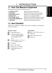
..." and (2) 3.5" floppy disk drives (1) I/O Shield (1) Bag of spare jumpers (1) Support drivers and utilities (1) This Motherboard User's Manual Optional Items ASUS 3-port USB connector set with bracket ASUS consumer infrared set Modem riser ASUS TUSI-M User's Manual 7 If you discover damaged or missing items, contact your package is divided into the following sections: 1. SOFTWARE SETUP...
..." and (2) 3.5" floppy disk drives (1) I/O Shield (1) Bag of spare jumpers (1) Support drivers and utilities (1) This Motherboard User's Manual Optional Items ASUS 3-port USB connector set with bracket ASUS consumer infrared set Modem riser ASUS TUSI-M User's Manual 7 If you discover damaged or missing items, contact your package is divided into the following sections: 1. SOFTWARE SETUP...
TUSI-M User Manual
Page 8
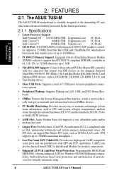
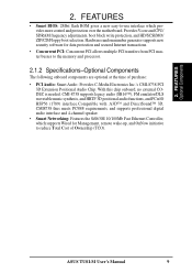
ler supports a 133MHz Front Side Bus (FSB) and UltraDMA/100, which is carefully designed for virtually automatic setup. 8 ASUS TUSI-M User's Manual 2. FEATURES Specifications 2. Supports UltraDMA/100/66/33, PIO Modes 3 & 4 and Bus Master IDE DMA ...Supports a total of 5 USB ports for more peripheral connectivity options. • Peripheral Wakeup: Supports Wakeup on two channels. FEATURES 2.1 The ASUS TUSI-M The ASUS TUSI-M motherboard is used to physically transport commands and information between SMBus devices. • PC Health Monitoring: Provides an easy way to 1GB. ...
ler supports a 133MHz Front Side Bus (FSB) and UltraDMA/100, which is carefully designed for virtually automatic setup. 8 ASUS TUSI-M User's Manual 2. FEATURES Specifications 2. Supports UltraDMA/100/66/33, PIO Modes 3 & 4 and Bus Master IDE DMA ...Supports a total of 5 USB ports for more peripheral connectivity options. • Peripheral Wakeup: Supports Wakeup on two channels. FEATURES 2.1 The ASUS TUSI-M The ASUS TUSI-M motherboard is used to physically transport commands and information between SMBus devices. • PC Health Monitoring: Provides an easy way to 1GB. ...
TUSI-M User Manual
Page 9
... 4-channel speaker. • Smart Networking: Features the SiS630E 10/100Mb Fast Ethernet Controller, which provides more control and protection over the motherboard. 2. FEATURES Optional Components 2. ASUS TUSI-M User's Manual 9 Provides Vcore and CPU/ SDRAM frequency adjustments, boot block write protection, and HD/SCSI/MO/ ZIP/CD/Floppy boot selection.
... 4-channel speaker. • Smart Networking: Features the SiS630E 10/100Mb Fast Ethernet Controller, which provides more control and protection over the motherboard. 2. FEATURES Optional Components 2. ASUS TUSI-M User's Manual 9 Provides Vcore and CPU/ SDRAM frequency adjustments, boot block write protection, and HD/SCSI/MO/ ZIP/CD/Floppy boot selection.
TUSI-M User Manual
Page 10
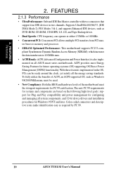
... can be used. • New Compliancy: Both the BIOS and hardware levels of ACPI, an ACPI-supported OS, such as required by PC 99. 10 ASUS TUSI-M User's Manual To fully utilize the benefits of the motherboard meet the stringent requirements for configuring and managing all... ASUS smart series motherboards. FEATURES 2.1.3 Performance • UltraPerformance: Onboard IDE Bus Master controller with two connectors that support four IDE devices in the OS, PCs can ...
... can be used. • New Compliancy: Both the BIOS and hardware levels of ACPI, an ACPI-supported OS, such as required by PC 99. 10 ASUS TUSI-M User's Manual To fully utilize the benefits of the motherboard meet the stringent requirements for configuring and managing all... ASUS smart series motherboards. FEATURES 2.1.3 Performance • UltraPerformance: Onboard IDE Bus Master controller with two connectors that support four IDE devices in the OS, PCs can ...
TUSI-M User Manual
Page 11
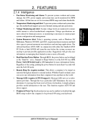
... in conjunction with either the bundled ASUS PC Probe or Intel LDCM will warn the user before the system resources are more memory and hard drive space to prevent possible application crashes. ... for future processors, so monitoring is necessary to ensure proper system configuration and management. • System Resources Alert: Today's operating systems, such as information providers. ASUS TUSI-M User's Manual 11
... in conjunction with either the bundled ASUS PC Probe or Intel LDCM will warn the user before the system resources are more memory and hard drive space to prevent possible application crashes. ... for future processors, so monitoring is necessary to ensure proper system configuration and management. • System Resources Alert: Today's operating systems, such as information providers. ASUS TUSI-M User's Manual 11
TUSI-M User Manual
Page 12
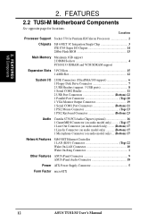
Location Processor Support Socket 370 for locations. FEATURES MB Components 2. 2. FEATURES 2.2 TUSI-M Motherboard Components See opposite page for Pentium III/Celeron Processors 2 Chipsets SiS 630ET 3C Integration Single Chip 3 ITE 8705 Super I/O Chipset 14 2Mbit ...only) ... (Bottom) 17 Network Features SiS630ET Ethernet Controller 1 LAN (RJ45) Connector Top) 22 Wake-On-LAN Connector 10 Wake-On-Ring Connector 1 Other Features ASUS iPanel Connector 9 ASUS iPanel Audio Connector 18 Power ATX Power Supply Connector 5 Form Factor microATX 12 ASUS TUSI-M User's Manual
Location Processor Support Socket 370 for locations. FEATURES MB Components 2. 2. FEATURES 2.2 TUSI-M Motherboard Components See opposite page for Pentium III/Celeron Processors 2 Chipsets SiS 630ET 3C Integration Single Chip 3 ITE 8705 Super I/O Chipset 14 2Mbit ...only) ... (Bottom) 17 Network Features SiS630ET Ethernet Controller 1 LAN (RJ45) Connector Top) 22 Wake-On-LAN Connector 10 Wake-On-Ring Connector 1 Other Features ASUS iPanel Connector 9 ASUS iPanel Audio Connector 18 Power ATX Power Supply Connector 5 Form Factor microATX 12 ASUS TUSI-M User's Manual
TUSI-M User Manual
Page 14
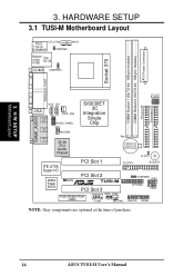
JP0 3. H/W SETUP Motherboard Layout 3. HARDWARE SETUP 3.1 TUSI-M Motherboard Layout 01 PS/2 CPU_FAN T: Mouse B: Keyboard PWRTMP WOR Bottom: Top: USB1 USB2 RJ-45 COM1 USBPWR1 ATX Power Connector DIMM Socket 2 (64/72-bit, ...-bit PCI Audio Chipset Row 0 1 2 3 CR2032 3V Lithium Cell CMOS Power CLRTC ITE 8705 Super I/O 2Mbit Flash BIOS PCI Slot 1 FLOPPY BUZZER PCI Slot 2 JEN R TUSI-M PCI Slot 3 USBPWR0 USB1 AFPANEL USB2 Audio Modem Riser (AMR) WOL_CON COM2 CH_FAN IDELED PANEL NOTE: Gray components are optional at the time of purchase...
JP0 3. H/W SETUP Motherboard Layout 3. HARDWARE SETUP 3.1 TUSI-M Motherboard Layout 01 PS/2 CPU_FAN T: Mouse B: Keyboard PWRTMP WOR Bottom: Top: USB1 USB2 RJ-45 COM1 USBPWR1 ATX Power Connector DIMM Socket 2 (64/72-bit, ...-bit PCI Audio Chipset Row 0 1 2 3 CR2032 3V Lithium Cell CMOS Power CLRTC ITE 8705 Super I/O 2Mbit Flash BIOS PCI Slot 1 FLOPPY BUZZER PCI Slot 2 JEN R TUSI-M PCI Slot 3 USBPWR0 USB1 AFPANEL USB2 Audio Modem Riser (AMR) WOL_CON COM2 CH_FAN IDELED PANEL NOTE: Gray components are optional at the time of purchase...
TUSI-M User Manual
Page 15
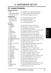
... (2 pin) p.32 Wake-On-LAN Connector (3 pin) p.33 USB Connector Set (10-1 pins, 5-1 pin) p.33 Internal Audio Connectors (Two 4 pin) (optional) p.34 ASUS iPanel Connector (12-1 pin) p.34 ASUS Audio Panel Connector (12-1 pin) p.35 ATX Power Supply Connector (20 pin) p.35 Power Supply Thermal Sensor Connector (2 pin) p.36 System Warning Speaker...) p.36 System MessageLED Lead (2 pin) p.36 System Management Interrupt Switch Lead (2 pin) p.36 ATX Power / Soft-Off Switch Lead (2 pin) p.36 Reset Switch Lead (2 pin) ASUS TUSI-M User's Manual 15 3. H/W SETUP Layout Contents 3.
... (2 pin) p.32 Wake-On-LAN Connector (3 pin) p.33 USB Connector Set (10-1 pins, 5-1 pin) p.33 Internal Audio Connectors (Two 4 pin) (optional) p.34 ASUS iPanel Connector (12-1 pin) p.34 ASUS Audio Panel Connector (12-1 pin) p.35 ATX Power Supply Connector (20 pin) p.35 Power Supply Thermal Sensor Connector (2 pin) p.36 System Warning Speaker...) p.36 System MessageLED Lead (2 pin) p.36 System Management Interrupt Switch Lead (2 pin) p.36 ATX Power / Soft-Off Switch Lead (2 pin) p.36 Reset Switch Lead (2 pin) ASUS TUSI-M User's Manual 15 3. H/W SETUP Layout Contents 3.
TUSI-M User Manual
Page 16
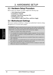
3. WARNING! Computer motherboards and expansion cards contain very delicate Integrated Circuit (IC) chips. H/W SETUP Motherboard Settings 16 ASUS TUSI-M User's Manual Unplug your computer when working on the motherboard. 3. Hold components by the edges and try not to a metal object, such as the power ...
3. WARNING! Computer motherboards and expansion cards contain very delicate Integrated Circuit (IC) chips. H/W SETUP Motherboard Settings 16 ASUS TUSI-M User's Manual Unplug your computer when working on the motherboard. 3. Hold components by the edges and try not to a metal object, such as the power ...
TUSI-M User Manual
Page 17
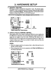
...™ mode, all computers have the appropriate ATX power supply. H/W SETUP Motherboard Settings 01 01 3 2 1 TUSI-M JEN 12 12 JumperFree Mode Jumper Mode TUSI-M JumperFree™ Mode Setting 2) USB Device Wake Up (USBPWR0, USBPWR1) These jumpers allow you set these to ...and do not have the appropriate ATX power supply. USBPWR1 2 1 Enable 3 2 Disable (Default) ® TUSI-M TUSI-M USB Device Wake Up USBPWR0 12 23 Enable Disable (Default) ASUS TUSI-M User's Manual 17 3. HARDWARE SETUP 1) JumperFree™ Mode (JEN) This jumper enableS or disableS the JumperFree...
...™ mode, all computers have the appropriate ATX power supply. H/W SETUP Motherboard Settings 01 01 3 2 1 TUSI-M JEN 12 12 JumperFree Mode Jumper Mode TUSI-M JumperFree™ Mode Setting 2) USB Device Wake Up (USBPWR0, USBPWR1) These jumpers allow you set these to ...and do not have the appropriate ATX power supply. USBPWR1 2 1 Enable 3 2 Disable (Default) ® TUSI-M TUSI-M USB Device Wake Up USBPWR0 12 23 Enable Disable (Default) ASUS TUSI-M User's Manual 17 3. HARDWARE SETUP 1) JumperFree™ Mode (JEN) This jumper enableS or disableS the JumperFree...
TUSI-M User Manual
Page 18
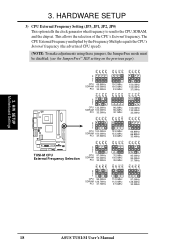
....5MHz 133.3MHz 133.3MHz 33.3MHz 66.8MHz 66.8MHz 33.4MHz JP2 JP1 JP3 JP0 JP2 JP1 JP3 JP0 JP2 JP1 JP3 ® TUSI-M TUSI-M CPU External Frequency Selection 3 2 1 CPU SDRAM PCI 97.0MHz 97.0MHz 32.3MHz 70.0MHz 105.0MHz 35.0MHz 95.0MHz 95.0MHz 31.7MHz... JP3 3 2 1 CPU 95.0MHz SDRAM 126.7MHz PCI 31.7MHz 112.0MHz 112.0MHz 37.3MHz 97.0MHz 129.3MHz 32.2MHz JP0 JP0 18 ASUS TUSI-M User's Manual H/W SETUP Motherboard Settings 3. 3.
....5MHz 133.3MHz 133.3MHz 33.3MHz 66.8MHz 66.8MHz 33.4MHz JP2 JP1 JP3 JP0 JP2 JP1 JP3 JP0 JP2 JP1 JP3 ® TUSI-M TUSI-M CPU External Frequency Selection 3 2 1 CPU SDRAM PCI 97.0MHz 97.0MHz 32.3MHz 70.0MHz 105.0MHz 35.0MHz 95.0MHz 95.0MHz 31.7MHz... JP3 3 2 1 CPU 95.0MHz SDRAM 126.7MHz PCI 31.7MHz 112.0MHz 112.0MHz 37.3MHz 97.0MHz 129.3MHz 32.2MHz JP0 JP0 18 ASUS TUSI-M User's Manual H/W SETUP Motherboard Settings 3. 3.
TUSI-M User Manual
Page 19
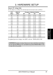
...MHz or else bootup will not be possible. 3. H/W SETUP Motherboard Settings ASUS TUSI-M User's Manual 19 Premature wearing of your processor as follows: CPU (... [1-2] [2-3] [2-3] [1-2] [2-3] [2-3] [1-2] [1-2] [2-3] [2-3] [2-3] [2-3] [1-2] [1-2] [1-2] [2-3] [1-2] [1-2] [2-3] [2-3] [2-3] [1-2] [1-2] [2-3] [2-3] [1-2] [2-3] [2-3] [1-2] [2-3] [1-2] [2-3] [1-2] [2-3] [2-3] [2-3] [2-3] [2-3] [1-2] [2-3] [2-3] [2-3] [2-3] For updated processor settings, visit ASUS's web site: WWW.ASUS.COM WARNING! 3. HARDWARE SETUP Manual CPU Settings Table Set the jumpers according to the internal speed...
...MHz or else bootup will not be possible. 3. H/W SETUP Motherboard Settings ASUS TUSI-M User's Manual 19 Premature wearing of your processor as follows: CPU (... [1-2] [2-3] [2-3] [1-2] [2-3] [2-3] [1-2] [1-2] [2-3] [2-3] [2-3] [2-3] [1-2] [1-2] [1-2] [2-3] [1-2] [1-2] [2-3] [2-3] [2-3] [1-2] [1-2] [2-3] [2-3] [1-2] [2-3] [2-3] [1-2] [2-3] [1-2] [2-3] [1-2] [2-3] [2-3] [2-3] [2-3] [2-3] [1-2] [2-3] [2-3] [2-3] [2-3] For updated processor settings, visit ASUS's web site: WWW.ASUS.COM WARNING! 3. HARDWARE SETUP Manual CPU Settings Table Set the jumpers according to the internal speed...
TUSI-M User Manual
Page 20
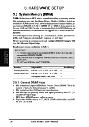
... than EDO (Ex- tended Data Output) chips. • BIOS shows SDRAM memory on the motherboard. double-sided come in 32, 64, 128, 256, 512MB. 20 ASUS TUSI-M User's Manual Sockets are generally thinner with 9 chips per side (standard 8 chips/side + 1 ECC chip). HARDWARE SETUP 3.5 System Memory (DIMM) NOTE: No hardware or BIOS...
... than EDO (Ex- tended Data Output) chips. • BIOS shows SDRAM memory on the motherboard. double-sided come in 32, 64, 128, 256, 512MB. 20 ASUS TUSI-M User's Manual Sockets are generally thinner with 9 chips per side (standard 8 chips/side + 1 ECC chip). HARDWARE SETUP 3.5 System Memory (DIMM) NOTE: No hardware or BIOS...
TUSI-M User Manual
Page 21
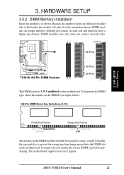
...will only fit in the orientation shown. This motherboard supports four clock signals. To determine the DIMM type, check the notches on both sides. ASUS TUSI-M User's Manual 21 You must be 3.3V Unbuffered for this motherboard. DIMM modules are different on either side of pins are longer and have...have the same pin contact on the DIMMs (see figure below). 168-Pin DIMM Notch Key Definitions (3.3V) 3. Lock 88 Pins 01 ® TUSI-M TUSI-M 168-Pin DIMM Sockets 60 Pins 20 Pins The DIMMs must ask your retailer the correct DIMM type before purchasing. H/W SETUP System Memory DRAM ...
...will only fit in the orientation shown. This motherboard supports four clock signals. To determine the DIMM type, check the notches on both sides. ASUS TUSI-M User's Manual 21 You must be 3.3V Unbuffered for this motherboard. DIMM modules are different on either side of pins are longer and have...have the same pin contact on the DIMMs (see figure below). 168-Pin DIMM Notch Key Definitions (3.3V) 3. Lock 88 Pins 01 ® TUSI-M TUSI-M 168-Pin DIMM Sockets 60 Pins 20 Pins The DIMMs must ask your retailer the correct DIMM type before purchasing. H/W SETUP System Memory DRAM ...
TUSI-M User Manual
Page 22
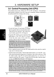
... does not fit, check its locked position. 4. Carefully attach the heatsink locking brace to 100 degrees). 2. CAUTION! A fan and heat- H/W SETUP CPU Notch Celeron ® TUSI-M TUSI-M Socket 370 Pentium III Gold Arrow 1. The socket lever must be oriented toward the outer corner of the CPU fan and heatsink locking brace, no... a clamp-style processor fan, or else damage may occur! Refer to set the correct Bus Frequency and Multiple (frequency multiple setting is not needed. 22 ASUS TUSI-M User's Manual
... does not fit, check its locked position. 4. Carefully attach the heatsink locking brace to 100 degrees). 2. CAUTION! A fan and heat- H/W SETUP CPU Notch Celeron ® TUSI-M TUSI-M Socket 370 Pentium III Gold Arrow 1. The socket lever must be oriented toward the outer corner of the CPU fan and heatsink locking brace, no... a clamp-style processor fan, or else damage may occur! Refer to set the correct Bus Frequency and Multiple (frequency multiple setting is not needed. 22 ASUS TUSI-M User's Manual


