TUSI-M User Manual
Page 1
R TUSI-M Socket 370 microATX Motherboard USER'S MANUAL
R TUSI-M Socket 370 microATX Motherboard USER'S MANUAL
TUSI-M User Manual
Page 12
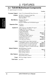
... Processor Support Socket 370 for locations. FEATURES MB Components 2. 2. FEATURES 2.2 TUSI-M Motherboard Components See opposite page for Pentium III/Celeron Processors 2 Chipsets SiS 630ET 3C Integration Single Chip 3 ITE 8705 Super I/O Chipset 14 2Mbit Flash BIOS 13 Main Memory Maximum 1GB support 2 DIMM Sockets 4 PC100/... 1 LAN (RJ45) Connector Top) 22 Wake-On-LAN Connector 10 Wake-On-Ring Connector 1 Other Features ASUS iPanel Connector 9 ASUS iPanel Audio Connector 18 Power ATX Power Supply Connector 5 Form Factor microATX 12 ASUS TUSI-M User's Manual
... Processor Support Socket 370 for locations. FEATURES MB Components 2. 2. FEATURES 2.2 TUSI-M Motherboard Components See opposite page for Pentium III/Celeron Processors 2 Chipsets SiS 630ET 3C Integration Single Chip 3 ITE 8705 Super I/O Chipset 14 2Mbit Flash BIOS 13 Main Memory Maximum 1GB support 2 DIMM Sockets 4 PC100/... 1 LAN (RJ45) Connector Top) 22 Wake-On-LAN Connector 10 Wake-On-Ring Connector 1 Other Features ASUS iPanel Connector 9 ASUS iPanel Audio Connector 18 Power ATX Power Supply Connector 5 Form Factor microATX 12 ASUS TUSI-M User's Manual
TUSI-M User Manual
Page 14
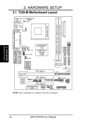
... JP0 3. HARDWARE SETUP 3.1 TUSI-M Motherboard Layout 01 PS/2 CPU_FAN T: Mouse B: Keyboard PWRTMP WOR Bottom: Top: USB1 USB2 RJ-45 COM1 USBPWR1 ATX Power Connector DIMM Socket 2 (64/72-bit, 168-pin module) DIMM Socket 1 (64/72-bit, 168-pin module) Socket 370 PARALLEL PORT JP2 JP1 JP3 Secondary... 2 3 CR2032 3V Lithium Cell CMOS Power CLRTC ITE 8705 Super I/O 2Mbit Flash BIOS PCI Slot 1 FLOPPY BUZZER PCI Slot 2 JEN R TUSI-M PCI Slot 3 USBPWR0 USB1 AFPANEL USB2 Audio Modem Riser (AMR) WOL_CON COM2 CH_FAN IDELED PANEL NOTE: Gray components are optional at the time...
... JP0 3. HARDWARE SETUP 3.1 TUSI-M Motherboard Layout 01 PS/2 CPU_FAN T: Mouse B: Keyboard PWRTMP WOR Bottom: Top: USB1 USB2 RJ-45 COM1 USBPWR1 ATX Power Connector DIMM Socket 2 (64/72-bit, 168-pin module) DIMM Socket 1 (64/72-bit, 168-pin module) Socket 370 PARALLEL PORT JP2 JP1 JP3 Secondary... 2 3 CR2032 3V Lithium Cell CMOS Power CLRTC ITE 8705 Super I/O 2Mbit Flash BIOS PCI Slot 1 FLOPPY BUZZER PCI Slot 2 JEN R TUSI-M PCI Slot 3 USBPWR0 USB1 AFPANEL USB2 Audio Modem Riser (AMR) WOL_CON COM2 CH_FAN IDELED PANEL NOTE: Gray components are optional at the time...
TUSI-M User Manual
Page 15
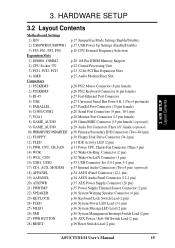
HARDWARE SETUP 3.2 Layout Contents Motherboard Settings 1) JEN 2) USBPWR0/USBPWR1 3) FS3, FS1, FS2, FS0 Expansion Slots 1) DIMM1, DIMM2 2) CPU Socket 370 3) PCI1, PCI2, PCI3 4) AMR Connectors 1) PS2KBMS 2) PS2KBMS 3) RJ-45 4) USB 5) PARALLEL 6) COM1/COM2 7) VGA1 8) GAME_AUDIO 9) GAME_AUDIO 10) PRIMARY/SECONDARYIDE 11) FLOPPY 12) PLED 13) PWR, ...) p.36 System MessageLED Lead (2 pin) p.36 System Management Interrupt Switch Lead (2 pin) p.36 ATX Power / Soft-Off Switch Lead (2 pin) p.36 Reset Switch Lead (2 pin) ASUS TUSI-M User's Manual 15 H/W SETUP Layout Contents 3. 3.
HARDWARE SETUP 3.2 Layout Contents Motherboard Settings 1) JEN 2) USBPWR0/USBPWR1 3) FS3, FS1, FS2, FS0 Expansion Slots 1) DIMM1, DIMM2 2) CPU Socket 370 3) PCI1, PCI2, PCI3 4) AMR Connectors 1) PS2KBMS 2) PS2KBMS 3) RJ-45 4) USB 5) PARALLEL 6) COM1/COM2 7) VGA1 8) GAME_AUDIO 9) GAME_AUDIO 10) PRIMARY/SECONDARYIDE 11) FLOPPY 12) PLED 13) PWR, ...) p.36 System MessageLED Lead (2 pin) p.36 System Management Interrupt Switch Lead (2 pin) p.36 ATX Power / Soft-Off Switch Lead (2 pin) p.36 Reset Switch Lead (2 pin) ASUS TUSI-M User's Manual 15 H/W SETUP Layout Contents 3. 3.
TUSI-M User Manual
Page 22
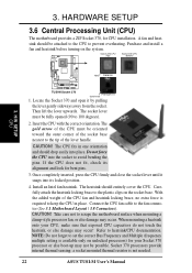
... corner of the socket base nearest to the tip of the CPU fan and heatsink locking brace, no extra force is required to set the correct Bus Frequency and Multiple (frequency multiple setting is not needed. 22 ASUS TUSI-M User's Manual...connector (See 3.1 Motherboard Layout / 3.8 Connectors). Connect the CPU fan cable to the plastic clips on the socket base. Refer to prevent overheating. 3. H/W SETUP CPU Notch Celeron ® TUSI-M TUSI-M Socket 370 Pentium III Gold Arrow 1. CAUTION! Socket 370 processors provide internal thermal sensing: a socket mounted thermal resistor is...
... corner of the socket base nearest to the tip of the CPU fan and heatsink locking brace, no extra force is required to set the correct Bus Frequency and Multiple (frequency multiple setting is not needed. 22 ASUS TUSI-M User's Manual...connector (See 3.1 Motherboard Layout / 3.8 Connectors). Connect the CPU fan cable to the plastic clips on the socket base. Refer to prevent overheating. 3. H/W SETUP CPU Notch Celeron ® TUSI-M TUSI-M Socket 370 Pentium III Gold Arrow 1. CAUTION! Socket 370 processors provide internal thermal sensing: a socket mounted thermal resistor is...


