TUEP2-M User Manual
Page 7
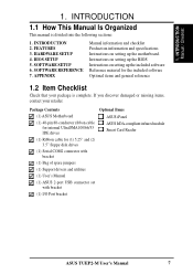
FEATURES 3. BIOS SETUP 5. SOFTWARE SETUP 6. Package Contents (1) ASUS Motherboard (1) 40-pin 80-conductor ribbon cable for internal UltraDMA100/66/33 IDE drives (1) Ribbon cable for the included ...3.5" floppy disk drives (1) Serial COM2 connector with bracket (1) Bag of spare jumpers (1) Support drivers and utilities (1) User's Manual (1) ASUS 2-port USB connector set with bracket (1) I/O Port bracket Optional Items ASUS iPanel ASUS IrDA-compliant infrared module Smart Card Reader ASUS TUEP2-M User's Manual 7 INTRODUCTION 1.1 How This Manual Is Organized This manual is complete.
FEATURES 3. BIOS SETUP 5. SOFTWARE SETUP 6. Package Contents (1) ASUS Motherboard (1) 40-pin 80-conductor ribbon cable for internal UltraDMA100/66/33 IDE drives (1) Ribbon cable for the included ...3.5" floppy disk drives (1) Serial COM2 connector with bracket (1) Bag of spare jumpers (1) Support drivers and utilities (1) User's Manual (1) ASUS 2-port USB connector set with bracket (1) I/O Port bracket Optional Items ASUS iPanel ASUS IrDA-compliant infrared module Smart Card Reader ASUS TUEP2-M User's Manual 7 INTRODUCTION 1.1 How This Manual Is Organized This manual is complete.
TUEP2-M User Manual
Page 8
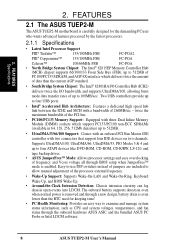
...of up to four USB ports. • Intel® Accelerated Hub Architecture: Features a dedicated high speed hub link between the ICH2 and MCH with two connectors that support four IDE devices on two channels. FEATURES Specifications 2. FEATURES 2.1 The ASUS TUEP2-M The ASUS TUEP2-M motherboard is carefully designed..., such as CPU and system voltages, temperatures, and fan status through the onboard hardware ASUS ASIC and the bundled ASUS PC Probe or Intel LDCM software. 8 ASUS TUEP2-M User's Manual The onboard battery supports detection even when normal power is removed and through...
...of up to four USB ports. • Intel® Accelerated Hub Architecture: Features a dedicated high speed hub link between the ICH2 and MCH with two connectors that support four IDE devices on two channels. FEATURES Specifications 2. FEATURES 2.1 The ASUS TUEP2-M The ASUS TUEP2-M motherboard is carefully designed..., such as CPU and system voltages, temperatures, and fan status through the onboard hardware ASUS ASIC and the bundled ASUS PC Probe or Intel LDCM software. 8 ASUS TUEP2-M User's Manual The onboard battery supports detection even when normal power is removed and through...
TUEP2-M User Manual
Page 9
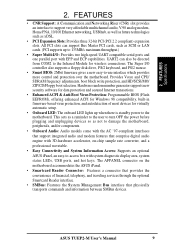
...Reader interface. • SMBus: Features the System Management Bus interface that physically transports commands and information between SMBus devices. FEATURES Specifications 2. ASUS TUEP2-M User's Manual 9 This acts as a reminder to the user to turn OFF the power before plugging and unplugging devices so as... up when there is standby power to support very affordable multichannel audio, V.90 analog modem, Home PNA, 10/100 Ethernet networking, USB hub, as well as future technologies such as not to damage the motherboard, peripherals, and/or components. • Onboard Audio:...
...Reader interface. • SMBus: Features the System Management Bus interface that physically transports commands and information between SMBus devices. FEATURES Specifications 2. ASUS TUEP2-M User's Manual 9 This acts as a reminder to the user to turn OFF the power before plugging and unplugging devices so as... up when there is standby power to support very affordable multichannel audio, V.90 analog modem, Home PNA, 10/100 Ethernet networking, USB hub, as well as future technologies such as not to damage the motherboard, peripherals, and/or components. • Onboard Audio:...

TUEP2-M User Manual
Page 12
FEATURES MB Components 2. Location Processor Support Socket 370 for locations. FEATURES 2.2 TUEP2-M Motherboard Components See opposite page for Pentium III/Celeron/Tualatin CPUs 2 Feature Setting DIP Switches 8 Chipsets Intel 82815EP Memory Controller Hub ... 10 1 Floppy Disk Drive Connector 5 2 IDE Connectors (UltraDMA/100 Support 6 1 Serial COM2 Header 23 1 ASUS iPanel Connector 9 1 Parallel Port Connector Top) 24 1 Serial COM1 Port Connector Bottom) 25 2 USB Port Connectors Bottom) 26 1 PS/2 Mouse Connector Top) 27 1 PS/2 Keyboard Connector Bottom) 27 Audio AC'97 ...
FEATURES MB Components 2. Location Processor Support Socket 370 for locations. FEATURES 2.2 TUEP2-M Motherboard Components See opposite page for Pentium III/Celeron/Tualatin CPUs 2 Feature Setting DIP Switches 8 Chipsets Intel 82815EP Memory Controller Hub ... 10 1 Floppy Disk Drive Connector 5 2 IDE Connectors (UltraDMA/100 Support 6 1 Serial COM2 Header 23 1 ASUS iPanel Connector 9 1 Parallel Port Connector Top) 24 1 Serial COM1 Port Connector Bottom) 25 2 USB Port Connectors Bottom) 26 1 PS/2 Mouse Connector Top) 27 1 PS/2 Keyboard Connector Bottom) 27 Audio AC'97 ...

TUEP2-M User Manual
Page 14
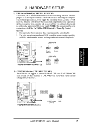
HARDWARE SETUP 3.1 TUEP2-M Motherboard Layout PS/2KBMS T: Mouse B: Keyboard USB T: USB1 Top: RJ-45 B: USB2 CPU_FAN DIMM1 (64/72 bit, 168-pin module) DIMM2 (64/72 ... (AGP) ® 1 1 1 CR2032 3V Lithium Cell CMOS Power AAPANEL PCI1 CD Audio Codec AUD_EN TUEP2-M PCI2 LAN_EN WOL_CON 3Com 3C920 Fast Ethernet PCI3 CNR_SLOT CHA_FAN Intel I/O Controller Hub (ICH2) CLRTC 2Mbit Firmware Hub (FWH) USB2 JTPWR... models only. The components are optional components, and present in the above motherboard layout. 14 ASUS TUEP2-M User's Manual H/W SETUP Motherboard Layout 3. 3.
HARDWARE SETUP 3.1 TUEP2-M Motherboard Layout PS/2KBMS T: Mouse B: Keyboard USB T: USB1 Top: RJ-45 B: USB2 CPU_FAN DIMM1 (64/72 bit, 168-pin module) DIMM2 (64/72 ... (AGP) ® 1 1 1 CR2032 3V Lithium Cell CMOS Power AAPANEL PCI1 CD Audio Codec AUD_EN TUEP2-M PCI2 LAN_EN WOL_CON 3Com 3C920 Fast Ethernet PCI3 CNR_SLOT CHA_FAN Intel I/O Controller Hub (ICH2) CLRTC 2Mbit Firmware Hub (FWH) USB2 JTPWR... models only. The components are optional components, and present in the above motherboard layout. 14 ASUS TUEP2-M User's Manual H/W SETUP Motherboard Layout 3. 3.
TUEP2-M User Manual
Page 15
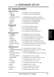
...18 JumperFree™ Mode (Enable/Disable) 2) USBPWR1 USBPWR2 p. 19 USB Device Wake Up (Enable/Disable) 3) USBCNR1/USBCNR2 p. 19 USB/CNR Selection (USB2 Connect/CNR) 4) AUD_EN1 p. 20 Onboard Audio ... Mouse Connector (6-pin female) 2) PS2KBMS p. 30 PS/2 Keyboard Connector (6-pin female) 3) USB p. 31 Universal Serial Bus Ports (Two 4-pin female) 4) PRINTER p. 31 Parallel Port ...pins) 7) MIC2 p. 37 Internal Microphone Connector (3 pins) 8) AFPANEL p. 37 ASUS iPanel Connector (24-1 pins) 9) AAPANEL p. 37 ASUS iPanel Audio Connector (10-1 pins) 10) SMB p. 38 SMBus Connector (6-1 pins...
...18 JumperFree™ Mode (Enable/Disable) 2) USBPWR1 USBPWR2 p. 19 USB Device Wake Up (Enable/Disable) 3) USBCNR1/USBCNR2 p. 19 USB/CNR Selection (USB2 Connect/CNR) 4) AUD_EN1 p. 20 Onboard Audio ... Mouse Connector (6-pin female) 2) PS2KBMS p. 30 PS/2 Keyboard Connector (6-pin female) 3) USB p. 31 Universal Serial Bus Ports (Two 4-pin female) 4) PRINTER p. 31 Parallel Port ...pins) 7) MIC2 p. 37 Internal Microphone Connector (3 pins) 8) AFPANEL p. 37 ASUS iPanel Connector (24-1 pins) 9) AAPANEL p. 37 ASUS iPanel Audio Connector (10-1 pins) 10) SMB p. 38 SMBus Connector (6-1 pins...

TUEP2-M User Manual
Page 16
H/W SETUP Layout Contents 16 ASUS TUEP2-M User's Manual 3. HARDWARE SETUP 14) USB2 15) ATXPWR 16) PWRLED (PANEL) 17) KEYLOCK (PANEL) 18) SPEAKER (PANEL) 19) MSG.LED (PANEL) 20) SMI (PANEL) 21) PWRSW (PANEL) 22) RESET (PANEL) p. 40 USB Headers (5-1 pins) p. 41 ATX Power Supply Connector (20 pins) p. 42 System Power LED Lead (3-1 pins) p. 42...
H/W SETUP Layout Contents 16 ASUS TUEP2-M User's Manual 3. HARDWARE SETUP 14) USB2 15) ATXPWR 16) PWRLED (PANEL) 17) KEYLOCK (PANEL) 18) SPEAKER (PANEL) 19) MSG.LED (PANEL) 20) SMI (PANEL) 21) PWRSW (PANEL) 22) RESET (PANEL) p. 40 USB Headers (5-1 pins) p. 41 ATX Power Supply Connector (20 pins) p. 42 System Power LED Lead (3-1 pins) p. 42...
TUEP2-M User Manual
Page 19
... to wake up function. CNRUSB1 CNRUSB2 12 ® TUEP2-M TUEP2-M USB/CNR Selection USB2 Connect (default) 23 CNR ASUS TUEP2-M User's Manual 19 H/W SETUP Motherboard Settings 3. If a USB hub CNR card is set in conjunction with Wake On USB for STR State in the sleep mode. HARDWARE SETUP 2) USB Device Wake Up (USBPWR1,USBPWR2) These allow you to...
... to wake up function. CNRUSB1 CNRUSB2 12 ® TUEP2-M TUEP2-M USB/CNR Selection USB2 Connect (default) 23 CNR ASUS TUEP2-M User's Manual 19 H/W SETUP Motherboard Settings 3. If a USB hub CNR card is set in conjunction with Wake On USB for STR State in the sleep mode. HARDWARE SETUP 2) USB Device Wake Up (USBPWR1,USBPWR2) These allow you to...

TUEP2-M User Manual
Page 28
... 1 PCI slot 2 PCI slot 3 Onboard USB controller HC0 Onboard USB controller HC1 AGP CNR LAN CNR Audio/Modem Onboard LAN ABCDE FGH - - - - - not shared shared shared not shared - - - - not shared not shared - - - - - IMPORTANT: If using PCI cards on shared slots, make the system unstable or cards inoperable. 28 ASUS TUEP2-M User's Manual 3. H/W SETUP Expansion...
... 1 PCI slot 2 PCI slot 3 Onboard USB controller HC0 Onboard USB controller HC1 AGP CNR LAN CNR Audio/Modem Onboard LAN ABCDE FGH - - - - - not shared shared shared not shared - - - - not shared not shared - - - - - IMPORTANT: If using PCI cards on shared slots, make the system unstable or cards inoperable. 28 ASUS TUEP2-M User's Manual 3. H/W SETUP Expansion...

TUEP2-M User Manual
Page 31
.... H/W SETUP Connectors ASUS TUEP2-M User's Manual 31 For additional USB ports, you can enable the parallel port and choose the IRQ through Onboard Parallel Port (see USB Headers later in this section) and mount it to the serial port. USB 1 Universal Serial Bus (USB) 2 4) Parallel ...Port Connector (Burgundy 25-pin PRINTER) You can use the USB headers (see 4.4.2 I/O Device Configuration). Parallel (Printer)...
.... H/W SETUP Connectors ASUS TUEP2-M User's Manual 31 For additional USB ports, you can enable the parallel port and choose the IRQ through Onboard Parallel Port (see USB Headers later in this section) and mount it to the serial port. USB 1 Universal Serial Bus (USB) 2 4) Parallel ...Port Connector (Burgundy 25-pin PRINTER) You can use the USB headers (see 4.4.2 I/O Device Configuration). Parallel (Printer)...

TUEP2-M User Manual
Page 33
... 8) Fast-Ethernet Port Connector (RJ-45) (optional) The RJ-45 connector is optional at the time of purchase and is located on top of the USB connectors. HARDWARE SETUP 7) Audio Port Connectors (Three 1/8" GAME_AUDIO) (optional) Line Out (lime) can be connected for inputting voice. H/W SETUUPP DCMoAnnCehcatnornsels ASUS TUEP2-M User's Manual 33
... 8) Fast-Ethernet Port Connector (RJ-45) (optional) The RJ-45 connector is optional at the time of purchase and is located on top of the USB connectors. HARDWARE SETUP 7) Audio Port Connectors (Three 1/8" GAME_AUDIO) (optional) Line Out (lime) can be connected for inputting voice. H/W SETUUPP DCMoAnnCehcatnornsels ASUS TUEP2-M User's Manual 33
TUEP2-M User Manual
Page 40
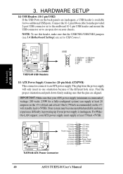
... +5V Standby +12.0 Volts 40 ASUS TUEP2-M User's Manual Your system may become unstable/unreliable and may experience difficulty in one orientation because of the different hole sizes. The plug from the provided 2-port USB connector set to the midboard 10-1 pin USB header and mount the USB connector set to USB Connect. 3. Find the proper...
... +5V Standby +12.0 Volts 40 ASUS TUEP2-M User's Manual Your system may become unstable/unreliable and may experience difficulty in one orientation because of the different hole sizes. The plug from the provided 2-port USB connector set to the midboard 10-1 pin USB header and mount the USB connector set to USB Connect. 3. Find the proper...
TUEP2-M User Manual
Page 59
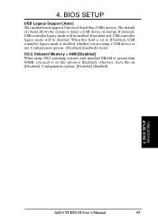
... 64MB, you are using OS/2 operating systems with installed DRAM of [Auto] allows the system to detect a USB device on [Disabled]. If not detected, USB controller legacy mode will be disabled. BIOS SETUP Advanced Menu ASUS TUEP2-M User's Manual 59 otherwise, leave this option to [Disabled], USB controller legacy mode is set this on startup. 4.
... 64MB, you are using OS/2 operating systems with installed DRAM of [Auto] allows the system to detect a USB device on [Disabled]. If not detected, USB controller legacy mode will be disabled. BIOS SETUP Advanced Menu ASUS TUEP2-M User's Manual 59 otherwise, leave this option to [Disabled], USB controller legacy mode is set this on startup. 4.
TUEP2-M User Manual
Page 67
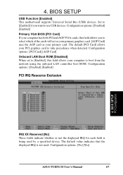
... by a specified device. Configuration options: [No] [Yes] ASUS TUEP2-M User's Manual 67 The default [PCI Card] allows your PCI graphics card to select which of the cards will act as your primary graphics card. [AGP Card] uses the AGP card as your computer to use USB devices. Configuration options: [Disabled] [Enabled] Primary VGA...
... by a specified device. Configuration options: [No] [Yes] ASUS TUEP2-M User's Manual 67 The default [PCI Card] allows your PCI graphics card to select which of the cards will act as your primary graphics card. [AGP Card] uses the AGP card as your computer to use USB devices. Configuration options: [Disabled] [Enabled] Primary VGA...
TUEP2-M User Manual
Page 72
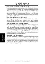
..., such as Windows 98, which have the appropriate ATX power supply. Configuration options: [Space Bar] [Ctrl-Esc] [Power Key] [Wakeup Key] Wake On USB for S3 or S4 State [Disabled] This field allows you to use your system to [Enabled] and do not have the appropriate ATX power supply... have ACPI support enabled. NOTE: Automatic Power Up will not power ON if you wish to use your computer. BIOS SETUP Power Up Control 72 ASUS TUEP2-M User's Manual The default is powered down by selecting [By Date]. Configuration options: [Disabled] [Enabled] Wake Up By PS2 Keyboard [Space Bar] When ...
..., such as Windows 98, which have the appropriate ATX power supply. Configuration options: [Space Bar] [Ctrl-Esc] [Power Key] [Wakeup Key] Wake On USB for S3 or S4 State [Disabled] This field allows you to use your system to [Enabled] and do not have the appropriate ATX power supply... have ACPI support enabled. NOTE: Automatic Power Up will not power ON if you wish to use your computer. BIOS SETUP Power Up Control 72 ASUS TUEP2-M User's Manual The default is powered down by selecting [By Date]. Configuration options: [Disabled] [Enabled] Wake Up By PS2 Keyboard [Space Bar] When ...

TUEP2-M User Manual
Page 80
... both Administrator and Client software. • Intel LDCM Client Setup: Installs software to monitor your computer's fan, temperature, and voltages. 80 ASUS TUEP2-M User's Manual S/W SETUP Applications 5.2.2 Applications • INF Update Utility for Intel 815 Chipset: Installs INF files in Windows for the following... items: System and Graphics, LPC Interface, SM Bus, PCI Bridge, Bus Master IDE, USB Host, and Controllers. • Intel Ultra ATA Storage Driver: Installs Intel's Ultra ATA storage driver. • Intel(r) AC'97 Audio...
... both Administrator and Client software. • Intel LDCM Client Setup: Installs software to monitor your computer's fan, temperature, and voltages. 80 ASUS TUEP2-M User's Manual S/W SETUP Applications 5.2.2 Applications • INF Update Utility for Intel 815 Chipset: Installs INF files in Windows for the following... items: System and Graphics, LPC Interface, SM Bus, PCI Bridge, Bus Master IDE, USB Host, and Controllers. • Intel Ultra ATA Storage Driver: Installs Intel's Ultra ATA storage driver. • Intel(r) AC'97 Audio...
TUEP2-M User Manual
Page 97
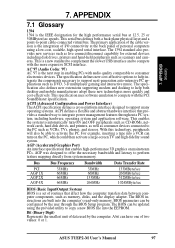
..., phones, and stereos. With this technology, peripherals will also be updated using a low-cost, scalable, high-speed serial interface. ASUS TUEP2-M User's Manual 97 This serial bus defines both desktop and mobile manufacturers adopt these new technologies more expensive SCSI interface. AC'97 .../sec 266MByte/sec 512MByte/sec 1024MByte/sec BIOS (Basic Input/Output System) BIOS is a new standard to complement the slower USB interface and to integrate power management features throughout a PC system, including hardware, operating system and application software. BIOS parameters can...
..., phones, and stereos. With this technology, peripherals will also be updated using a low-cost, scalable, high-speed serial interface. ASUS TUEP2-M User's Manual 97 This serial bus defines both desktop and mobile manufacturers adopt these new technologies more expensive SCSI interface. AC'97 .../sec 266MByte/sec 512MByte/sec 1024MByte/sec BIOS (Basic Input/Output System) BIOS is a new standard to complement the slower USB interface and to integrate power management features throughout a PC system, including hardware, operating system and application software. BIOS parameters can...

TUEP2-M User Manual
Page 100
...USB (Universal Serial Bus) A 4-pin serial cable bus that identifies the module type and various SDRAM organization and timing parameters. Ultra ATA/66, also known as keyboard, mouse, joystick, scanner, printer, modem, and monitor to 66.6 Mbytes/sec and maximized disk performance under power soft-off, suspend or sleep mode. 100 ASUS TUEP2... computer automatically wakes up upon receiving a wake-up to USB 1.0 and competes with an accelerated 3D geometry pipeline and support for new applications, such as the data transfer. USB 2.0 provides twice the transfer rate compared to 127 plug ...
...USB (Universal Serial Bus) A 4-pin serial cable bus that identifies the module type and various SDRAM organization and timing parameters. Ultra ATA/66, also known as keyboard, mouse, joystick, scanner, printer, modem, and monitor to 66.6 Mbytes/sec and maximized disk performance under power soft-off, suspend or sleep mode. 100 ASUS TUEP2... computer automatically wakes up upon receiving a wake-up to USB 1.0 and competes with an accelerated 3D geometry pipeline and support for new applications, such as the data transfer. USB 2.0 provides twice the transfer rate compared to 127 plug ...

TUEP2-M User Manual
Page 101
...-Ethernet Port Connector 33 Floppy 3 Mode Support 52 Floppy Disk Access Control 64 Floppy Disk Drive Connector 34 ASUS iPanel Audio 37 ATX Power Supply 41 Audio Port 33 Fast-Ethernet Port 33 ASUS TUEP2-M User's Manual 101 INDEX A AC PWR Loss Restart 71 Accessories CIDB Intrusion Detection Module. See also Leads: Chassis... IDE 34 Internal Audio 36 Internal Microphone 37 Monitor Output 32 Parallel Port 31 PS/2 Keyboard 30 PS/2 Mouse 30 Serial Port 32 SMB 38 USB 31 Wake-On-LAN 39 Wake-On-Ring 39 CPU Latency Timer 62 CyberLink PowerPlayer SE 93 VideoLive Mail 94 BIOS Beep Code 43 Updating...
...-Ethernet Port Connector 33 Floppy 3 Mode Support 52 Floppy Disk Access Control 64 Floppy Disk Drive Connector 34 ASUS iPanel Audio 37 ATX Power Supply 41 Audio Port 33 Fast-Ethernet Port 33 ASUS TUEP2-M User's Manual 101 INDEX A AC PWR Loss Restart 71 Accessories CIDB Intrusion Detection Module. See also Leads: Chassis... IDE 34 Internal Audio 36 Internal Microphone 37 Monitor Output 32 Parallel Port 31 PS/2 Keyboard 30 PS/2 Mouse 30 Serial Port 32 SMB 38 USB 31 Wake-On-LAN 39 Wake-On-Ring 39 CPU Latency Timer 62 CyberLink PowerPlayer SE 93 VideoLive Mail 94 BIOS Beep Code 43 Updating...

TUEP2-M User Manual
Page 102
... Heads 54 LBA Capacity 54 Sectors 54 Translation Method 54 Types 53 Hardware Setup CPU Installation 26 HDD Power Down 70 Headers LCD-TV 40 USB 40 High Priority PCI Mode 63 I IDE Connectors 34 IDE Hard Drive 74 Installation CPU 26 Expansion Card 27 Installed Memory 57 Internal Audio Connectors... 2.1 Support 63 PCI Latency Timer 66 PCI/VGA Palette Snoop 66 PIO Mode 55 Plug & Play O/S 75 Power Fan Speed 73 Power Management 69 102 ASUS TUEP2-M User's Manual
... Heads 54 LBA Capacity 54 Sectors 54 Translation Method 54 Types 53 Hardware Setup CPU Installation 26 HDD Power Down 70 Headers LCD-TV 40 USB 40 High Priority PCI Mode 63 I IDE Connectors 34 IDE Hard Drive 74 Installation CPU 26 Expansion Card 27 Installed Memory 57 Internal Audio Connectors... 2.1 Support 63 PCI Latency Timer 66 PCI/VGA Palette Snoop 66 PIO Mode 55 Plug & Play O/S 75 Power Fan Speed 73 Power Management 69 102 ASUS TUEP2-M User's Manual


