User Guide
Page 3
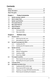
... 2.1 Chassis cover 2-2 2.1.1 Removing the side cover 2-2 2.1.2 Reinstalling the side cover 2-3 2.2 Central Processing Unit (CPU 2-4 2.2.1 Installing the CPU 2-4 2.2.2 Installing the CPU heatsink and fan 2-7 2.3 System memory 2-8 2.3.1 Overview 2-8 2.3.2 Memory Configurations 2-9 2.3.3 Installing a DIMM 2-10 2.3.4 Removing a DIMM 2-10 2.4 Front panel assembly 2-11 2.4.1 Removing the front panel assembly 2-11 2.4.2 Reinstalling the front panel assembly 2-11 2.5 5.25-inch...
... 2.1 Chassis cover 2-2 2.1.1 Removing the side cover 2-2 2.1.2 Reinstalling the side cover 2-3 2.2 Central Processing Unit (CPU 2-4 2.2.1 Installing the CPU 2-4 2.2.2 Installing the CPU heatsink and fan 2-7 2.3 System memory 2-8 2.3.1 Overview 2-8 2.3.2 Memory Configurations 2-9 2.3.3 Installing a DIMM 2-10 2.3.4 Removing a DIMM 2-10 2.4 Front panel assembly 2-11 2.4.1 Removing the front panel assembly 2-11 2.4.2 Reinstalling the front panel assembly 2-11 2.5 5.25-inch...
User Guide
Page 13
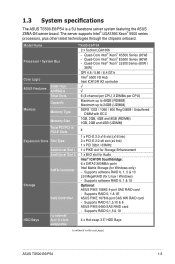
... x Hot-swap 3.5" HDD Bays swappable (continued on the next page) ASUS TS500-E6/PS4 1-3 Supports RAID 0, 1 & 1E SAS Controller ASUS PIKE 1078 8-port SAS HW RAID card - Model Name TS500-E6/PS4 2 x Socket LGA1366 Processor / System Bus - Quad-Core ...Intel® Xeon® E5500 Series (80W) - Supports RAID 0,1,5 & 10 I /O controller ASUS Features Smart Fan ASWM2.0 √ √ Total Slots 6 (3-channel per CPU, 3 DIMMs per CPU) Capacity Maximum up to 48GB (RDIMM) Maximum up to 24GB (UDIMM) Memory Memory...
... x Hot-swap 3.5" HDD Bays swappable (continued on the next page) ASUS TS500-E6/PS4 1-3 Supports RAID 0, 1 & 1E SAS Controller ASUS PIKE 1078 8-port SAS HW RAID card - Model Name TS500-E6/PS4 2 x Socket LGA1366 Processor / System Bus - Quad-Core ...Intel® Xeon® E5500 Series (80W) - Supports RAID 0,1,5 & 10 I /O controller ASUS Features Smart Fan ASWM2.0 √ √ Total Slots 6 (3-channel per CPU, 3 DIMMs per CPU) Capacity Maximum up to 48GB (RDIMM) Maximum up to 24GB (UDIMM) Memory Memory...
User Guide
Page 28
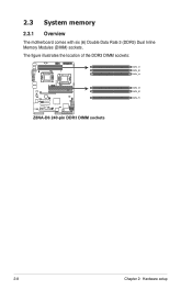
The figure illustrates the location of the DDR3 DIMM sockets: 2-8 Chapter 2: Hardware setup 2.3 System memory 2.3.1 Overview The motherboard comes with six (6) Double Data Rate 3 (DDR3) Dual Inline Memory Modules (DIMM) sockets.
The figure illustrates the location of the DDR3 DIMM sockets: 2-8 Chapter 2: Hardware setup 2.3 System memory 2.3.1 Overview The motherboard comes with six (6) Double Data Rate 3 (DDR3) Dual Inline Memory Modules (DIMM) sockets.
User Guide
Page 29
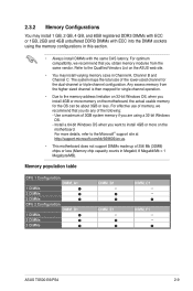
...dual-channel or triple-channel configuration. Use a maximum of 256 Mb (32MB) chips or less (Memory chip capacity counts in this section. • Always install DIMMs with the same CAS latency. For more memory on the motherboard. Any excess memory from the same vendor. DIMM_E1 -- The system maps the ... when you do any of the lower-sized channel for the OS can be about 3GB or less. ASUS TS500-E6/PS4 2-9 For optimum compatibility, we recommend that you obtain memory modules from the higher-sized channel is then mapped for single-channel operation. • Due to the ...
...dual-channel or triple-channel configuration. Use a maximum of 256 Mb (32MB) chips or less (Memory chip capacity counts in this section. • Always install DIMMs with the same CAS latency. For more memory on the motherboard. Any excess memory from the same vendor. DIMM_E1 -- The system maps the ... when you do any of the lower-sized channel for the OS can be about 3GB or less. ASUS TS500-E6/PS4 2-9 For optimum compatibility, we recommend that you obtain memory modules from the higher-sized channel is then mapped for single-channel operation. • Due to the ...
User Guide
Page 56
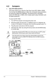
... ON the computer. 4. Move the jumper cap from pins 1-2 (default) to re-enter data. Clear RTC RAM (CLRTC1) This jumper allows you to clear the Real Time Clock (RTC) RAM in CMOS, which include system setup information such as system passwords. Removing the cap will cause system boot failure...! You can clear the CMOS memory of date, time, and system setup parameters by erasing the CMOS RTC RAM data. Hold down the key during the boot process and enter BIOS setup to pins 2-3. Except when ...
... ON the computer. 4. Move the jumper cap from pins 1-2 (default) to re-enter data. Clear RTC RAM (CLRTC1) This jumper allows you to clear the Real Time Clock (RTC) RAM in CMOS, which include system setup information such as system passwords. Removing the cap will cause system boot failure...! You can clear the CMOS memory of date, time, and system setup parameters by erasing the CMOS RTC RAM data. Hold down the key during the boot process and enter BIOS setup to pins 2-3. Except when ...
User Guide
Page 82
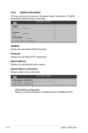
... UTILITY AMIBIOS Version :0204 Build Date :02/16/09 Processor Speed Count :2400MHZ :1 System Memory Usable Size : 1024MB System Memory Information AMIBIOS Displays the auto-detected BIOS information. System Memory Displays the auto-detected system memory. System Memory Information Displays system memory information. 5.3.6 System Information This menu gives you to check information of the general system...
... UTILITY AMIBIOS Version :0204 Build Date :02/16/09 Processor Speed Count :2400MHZ :1 System Memory Usable Size : 1024MB System Memory Information AMIBIOS Displays the auto-detected BIOS information. System Memory Displays the auto-detected system memory. System Memory Information Displays system memory information. 5.3.6 System Information This menu gives you to check information of the general system...
User Guide
Page 87
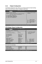
... transition the CSI links to Sub Screen F1 General Help F10 Save and Exit ESC Exit v02.61 (C)Copyright 1985-2009, American Megatrends, Inc. Memory Frequency Memory Mode Memory ECC Function Double Rate Refresh Demand Scrubbing Patrol Scrubbing NUMA Aware Page Policy [Auto] [Independent] [Enabled] [Auto] [Enabled] [Disabled] [Auto] [Closed] +F1 F10 ESC... 1985-2009, American Megatrends, Inc. 5.4.2 Chipset Configuration The Chipset configuration menu allows you to malfunction. Select an item then press to display the sub-menu. ASUS TS500-E6/PS4 5-17
... transition the CSI links to Sub Screen F1 General Help F10 Save and Exit ESC Exit v02.61 (C)Copyright 1985-2009, American Megatrends, Inc. Memory Frequency Memory Mode Memory ECC Function Double Rate Refresh Demand Scrubbing Patrol Scrubbing NUMA Aware Page Policy [Auto] [Independent] [Enabled] [Auto] [Enabled] [Disabled] [Auto] [Closed] +F1 F10 ESC... 1985-2009, American Megatrends, Inc. 5.4.2 Chipset Configuration The Chipset configuration menu allows you to malfunction. Select an item then press to display the sub-menu. ASUS TS500-E6/PS4 5-17
User Guide
Page 88
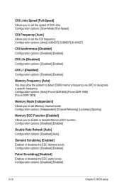
...[Enabled] Allows you to set the speed of CSI Links. CSI Links Speed [Full-Speed] Allows you to enable or disable Memory ECC fucntion. Configuration options: [Disabled] [Enabled] 5-18 Chapter 5: BIOS setup Configuration options: [Disabled] [Enabled] Patrol Scrubbing [... or disables the ECC patrol scrub. Configuration options: [Auto] [Force DDR-800] [Force DDR-1066] [Force DDR-1333] Memory Mode [Independent] Allows you to set Memory channel mode. Configuration options: [Disabled] [Enabled] Double Rate Refresh [Auto] Configuration options: [Disabled] [Auto] Demand Scrubbing [...
...[Enabled] Allows you to set the speed of CSI Links. CSI Links Speed [Full-Speed] Allows you to enable or disable Memory ECC fucntion. Configuration options: [Disabled] [Enabled] 5-18 Chapter 5: BIOS setup Configuration options: [Disabled] [Enabled] Patrol Scrubbing [... or disables the ECC patrol scrub. Configuration options: [Auto] [Force DDR-800] [Force DDR-1066] [Force DDR-1333] Memory Mode [Independent] Allows you to set Memory channel mode. Configuration options: [Disabled] [Enabled] Double Rate Refresh [Auto] Configuration options: [Disabled] [Auto] Demand Scrubbing [...
User Guide
Page 99
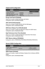
...Support [Enabled] Allows you to enable or disable the Energy Lake feature. Configuration options: [Disabled] [Enabled] ASUS TS500-E6/PS4 5-29 Chipset ACPI Configuration Advanced BIOS SETUP UTILITY South Bridge ACPI Configuration Energy Lake Feature APIC ACPI...Feature [Disabled] Allows you to enable or disable the High Performance Event Timer feature. Configuration options: [Disabled] [Enabled] HPET Memory Address [FED00000h] Configuration options: [FED00000h] [FED01000h] [FED02000h] [FED03000h] General WHEA Configuration Advanced BIOS SETUP UTILITY General WHEA ...
...Support [Enabled] Allows you to enable or disable the Energy Lake feature. Configuration options: [Disabled] [Enabled] ASUS TS500-E6/PS4 5-29 Chipset ACPI Configuration Advanced BIOS SETUP UTILITY South Bridge ACPI Configuration Energy Lake Feature APIC ACPI...Feature [Disabled] Allows you to enable or disable the High Performance Event Timer feature. Configuration options: [Disabled] [Enabled] HPET Memory Address [FED00000h] Configuration options: [FED00000h] [FED01000h] [FED02000h] [FED03000h] General WHEA Configuration Advanced BIOS SETUP UTILITY General WHEA ...
User Guide
Page 151
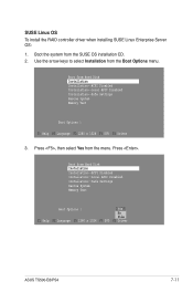
... Installation from Hard Disk Installation Installation--ACPI Disabled Installation--Local APIC Disabled Installation--Safe Settings Rescue System Memory Test Boot Options | Yes No File F1 Help F2 Language F3 1280 x 1024 F4 DVD F5 Driver ASUS TS500-E6/PS4 7-11 Boot from the Boot Options menu. Press . Boot from the menu. Press , then...
... Installation from Hard Disk Installation Installation--ACPI Disabled Installation--Local APIC Disabled Installation--Safe Settings Rescue System Memory Test Boot Options | Yes No File F1 Help F2 Language F3 1280 x 1024 F4 DVD F5 Driver ASUS TS500-E6/PS4 7-11 Boot from the Boot Options menu. Press . Boot from the menu. Press , then...
User Guide
Page 152
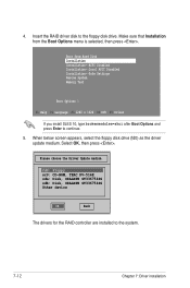
... installation Select OK, then press . Make sure that Installation from Hard Disk Installation Installation--ACPI Disabled Installation--Local APIC Disabled Installation--Safe Settings Rescue System Memory Test Boot Options | F1 Help F2 Language F3 1280 x 1024 F4 DVD F5 Driver If you install SLES 10, type brokenmodules=ahci after Boot Options...
... installation Select OK, then press . Make sure that Installation from Hard Disk Installation Installation--ACPI Disabled Installation--Local APIC Disabled Installation--Safe Settings Rescue System Memory Test Boot Options | F1 Help F2 Language F3 1280 x 1024 F4 DVD F5 Driver If you install SLES 10, type brokenmodules=ahci after Boot Options...

