User Guide
Page 6
... Options 6-30 Exiting the Intel® Matrix Storage Manager 6-31 6.3.7 Rebuilding the RAID 6-31 6.3.8 Setting the Boot array in the BIOS Setup Utility 6-33 Chapter 7: Driver installation 7.1 RAID driver installation 7-2 7.1.1 Creating a RAID driver disk 7-2 7.1.2 Installing the RAID controller driver 7-5 7.2 Intel® chipset device installation 7-13 7.3 LAN driver installation 7-15 7.4 VGA driver installation 7-18 7.5 Management applications and utilities installation 7-20 7.5.1 Running the support DVD 7-20 7.5.2 Drivers menu 7-20 7.5.3 Utilities menu 7-21 7.5.4 Make disk...
... Options 6-30 Exiting the Intel® Matrix Storage Manager 6-31 6.3.7 Rebuilding the RAID 6-31 6.3.8 Setting the Boot array in the BIOS Setup Utility 6-33 Chapter 7: Driver installation 7.1 RAID driver installation 7-2 7.1.1 Creating a RAID driver disk 7-2 7.1.2 Installing the RAID controller driver 7-5 7.2 Intel® chipset device installation 7-13 7.3 LAN driver installation 7-15 7.4 VGA driver installation 7-18 7.5 Management applications and utilities installation 7-20 7.5.1 Running the support DVD 7-20 7.5.2 Drivers menu 7-20 7.5.3 Utilities menu 7-21 7.5.4 Make disk...
User Guide
Page 9
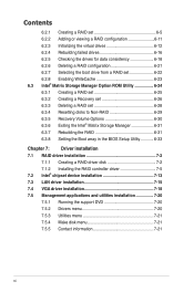
... enable proper reuse of the jumpers and internal connectors. 5. Chapter 3: Installation options This chapter describes how to change system settings through the BIOS Setup menus and describes the BIOS parameters. 6. Chapter 1: Product Introduction This chapter describes the general features of configuring a server. Chapter 2: Hardware setup This chapter lists the hardware setup procedures that the battery should not be placed in municipal waste. DO NOT throw the mercury-containing button cell battery...
... enable proper reuse of the jumpers and internal connectors. 5. Chapter 3: Installation options This chapter describes how to change system settings through the BIOS Setup menus and describes the BIOS parameters. 6. Chapter 1: Product Introduction This chapter describes the general features of configuring a server. Chapter 2: Hardware setup This chapter lists the hardware setup procedures that the battery should not be placed in municipal waste. DO NOT throw the mercury-containing button cell battery...
User Guide
Page 10
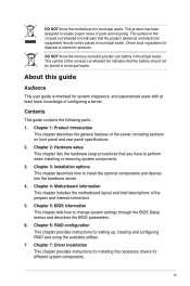
... the DOS prompt, type the command line: format A:/S Refer to complete a task. Italics Used to complete a task. Typography Bold text Indicates a menu or an item to set up and use the proprietary ASUS server management utility. 2. If you must press the Enter or Return key. Example: means that you must press the enclosed key. ASUS Server Web-based Management (ASWM) user guide This manual tells how to select...
... the DOS prompt, type the command line: format A:/S Refer to complete a task. Italics Used to complete a task. Typography Bold text Indicates a menu or an item to set up and use the proprietary ASUS server management utility. 2. If you must press the Enter or Return key. Example: means that you must press the enclosed key. ASUS Server Web-based Management (ASWM) user guide This manual tells how to select...
User Guide
Page 13
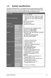
... I/O Hub Intel ICH10R I = internal HDD Bays A or S = hot- 4 x Hot-swap 3.5" HDD Bays swappable (continued on the next page) ASUS TS500-E6/PS4 1-3 Model Name TS500-E6/PS4 2 x Socket LGA1366 Processor / System Bus - Supports RAID 0,1,5 & 10 I /O controller ASUS Features Smart Fan ASWM2.0 √ √ Total Slots 6 (3-channel per CPU, 3 DIMMs per CPU) Capacity Maximum up to 48GB (RDIMM) Maximum up to 24GB (UDIMM) Memory Memory Type DDR3 1333 / 1066 / 800...
... I/O Hub Intel ICH10R I = internal HDD Bays A or S = hot- 4 x Hot-swap 3.5" HDD Bays swappable (continued on the next page) ASUS TS500-E6/PS4 1-3 Model Name TS500-E6/PS4 2 x Socket LGA1366 Processor / System Bus - Supports RAID 0,1,5 & 10 I /O controller ASUS Features Smart Fan ASWM2.0 √ √ Total Slots 6 (3-channel per CPU, 3 DIMMs per CPU) Capacity Maximum up to 48GB (RDIMM) Maximum up to 24GB (UDIMM) Memory Memory Type DDR3 1333 / 1066 / 800...
User Guide
Page 27
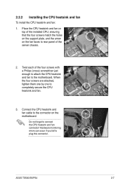
... the motherboard. Hardware monitoring errors can occur if you fail to completely secure the CPU heatsink and fan. 3. Place the CPU heatsink and fan on top of the server chassis. 2. 2.2.2 Installing the CPU heatsink and fan To install the CPU heatsink and fan: 1. When the four screws are attached, tighten them one by one to plug this connector. Connect the CPU heatsink and fan cable to the connector on the fan faces to rear panel...
... the motherboard. Hardware monitoring errors can occur if you fail to completely secure the CPU heatsink and fan. 3. Place the CPU heatsink and fan on top of the server chassis. 2. 2.2.2 Installing the CPU heatsink and fan To install the CPU heatsink and fan: 1. When the four screws are attached, tighten them one by one to plug this connector. Connect the CPU heatsink and fan cable to the connector on the fan faces to rear panel...
User Guide
Page 41
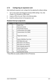
Refer to the card. Turn on BIOS setup. 2. Install the software drivers for ISA or PCI devices. Programmable Interrupt 3* 11 Communications Port (COM2) 4* 12 Communications Port (COM1) 5* 13 -- 6 14 Floppy Disk Controller 7* 15 -- 8 3 System CMOS/Real Time Clock 9* 4 ACPI Mode when used 10* 5 IRQ Holder for PCI Steering 11* 6 IRQ Holder for PCI Steering 12* 7 PS/2 Compatible Mouse Port 13 8 Numeric Data Processor 14* 9 Primary IDE Channel 15* 10 Secondary IDE Channel...
Refer to the card. Turn on BIOS setup. 2. Install the software drivers for ISA or PCI devices. Programmable Interrupt 3* 11 Communications Port (COM2) 4* 12 Communications Port (COM1) 5* 13 -- 6 14 Floppy Disk Controller 7* 15 -- 8 3 System CMOS/Real Time Clock 9* 4 ACPI Mode when used 10* 5 IRQ Holder for PCI Steering 11* 6 IRQ Holder for PCI Steering 12* 7 PS/2 Compatible Mouse Port 13 8 Numeric Data Processor 14* 9 Primary IDE Channel 15* 10 Secondary IDE Channel...
User Guide
Page 43
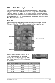
... connect to the front panel LEDs to support Serial ATA hard disk drives and SAS hard disk drives. HDD Device HDD 1 HDD 2 HDD 3 HDD 4 Front side connector HDD1 HDD2 HDD3 HDD4 Back side connector CON�1 CON�2 CON�3 CON�4 ASUS TS500-E6/PS4 2-23 2.8.2 SATA/SAS backplane connections A SATA/SAS backplane comes pre-installed in the TS500-E6. See section 1.7 LED information for the hot swap drive trays. Refer to allow easy connection or removal of SATA/SAS hard disks...
... connect to the front panel LEDs to support Serial ATA hard disk drives and SAS hard disk drives. HDD Device HDD 1 HDD 2 HDD 3 HDD 4 Front side connector HDD1 HDD2 HDD3 HDD4 Back side connector CON�1 CON�2 CON�3 CON�4 ASUS TS500-E6/PS4 2-23 2.8.2 SATA/SAS backplane connections A SATA/SAS backplane comes pre-installed in the TS500-E6. See section 1.7 LED information for the hot swap drive trays. Refer to allow easy connection or removal of SATA/SAS hard disks...
User Guide
Page 55
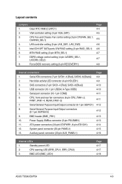
... 12. System panel connector (20-pin PANEL1) 13. Clear RTC RAM (CLRTC1) 2. LAN controller setting (3-pin LAN_SW1, LAN_SW2) 5. USB connector (10-1 pin USB34; VGA controller setting (3-pin VGA_SW1) 3. Serial ATA connectors (7-pin SATA1-4 [Red], SATA5-6 [Black]) 2. DDR3 voltage control setting (4-pin LVDDR3_SEL1, LVDDR3_SEL2) 8. Power Supply SMBus connector (5-pin PSUSMB1) 11. Intel ICH10R® SATA ports S/W RAID setting (3-pin RAID_SEL1) 6. Hard disk activity LED connector (4-pin HDLED1) 3. CPU warning LED (ERR_CPU1, ERR_CPU2) 3. A-Type USB5) 5.
... 12. System panel connector (20-pin PANEL1) 13. Clear RTC RAM (CLRTC1) 2. LAN controller setting (3-pin LAN_SW1, LAN_SW2) 5. USB connector (10-1 pin USB34; VGA controller setting (3-pin VGA_SW1) 3. Serial ATA connectors (7-pin SATA1-4 [Red], SATA5-6 [Black]) 2. DDR3 voltage control setting (4-pin LVDDR3_SEL1, LVDDR3_SEL2) 8. Power Supply SMBus connector (5-pin PSUSMB1) 11. Intel ICH10R® SATA ports S/W RAID setting (3-pin RAID_SEL1) 6. Hard disk activity LED connector (4-pin HDLED1) 3. CPU warning LED (ERR_CPU1, ERR_CPU2) 3. A-Type USB5) 5.
User Guide
Page 74
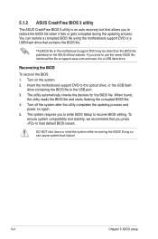
... enter BIOS Setup to recover BIOS setting. The BIOS file in the motherboard support DVD may be older than the BIOS file published on again. 5. To ensure system compatibility and stability, we recommend that allows you to restore the BIOS file when it to a USB flash drive. 5.1.2 ASUS CrashFree BIOS 3 utility The ASUS CrashFree BIOS 3 utility is an auto recovery tool that you press to load default BIOS values. You can cause system boot failure! 5-4 Chapter 5: BIOS setup...
... enter BIOS Setup to recover BIOS setting. The BIOS file in the motherboard support DVD may be older than the BIOS file published on again. 5. To ensure system compatibility and stability, we recommend that allows you to restore the BIOS file when it to a USB flash drive. 5.1.2 ASUS CrashFree BIOS 3 utility The ASUS CrashFree BIOS 3 utility is an auto recovery tool that you press to load default BIOS values. You can cause system boot failure! 5-4 Chapter 5: BIOS setup...

User Guide
Page 75
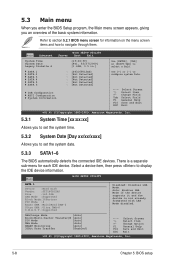
... this last option only if the first two failed. If you wish to enter Setup after changing any BIOS settings, load the default settings to ensure system compatibility and stability. Select the Load Default Settings item under the Exit Menu. 5.2 BIOS setup program This motherboard supports a programmable firmware chip that the computer can recognize these changes and record them in the CMOS RAM of your system, or prompted to "Run Setup."
... this last option only if the first two failed. If you wish to enter Setup after changing any BIOS settings, load the default settings to ensure system compatibility and stability. Select the Load Default Settings item under the Exit Menu. 5.2 BIOS setup program This motherboard supports a programmable firmware chip that the computer can recognize these changes and record them in the CMOS RAM of your system, or prompted to "Run Setup."
User Guide
Page 78
... with LBA Mode disabled. Main BIOS SETUP UTILITY SATA 1 Device :Hard Disk Vendor :ST3160812AS Size :160.0GB LBA Mode :Supported Block Mode:16Sectors PIO Mode :4 Async DMA :MultiWord DMA-2 Ultra DMA :Ultra DMA-6 S.M.A.R.T.:Supported Disabled: Disables LBA Mode. Change Option F1 General Help F10 Save and Exit ESC Exit v02.61 (C)Copyright 1985-2009, American Megatrends, Inc. 5-8 Chapter 5: BIOS setup Select a device item, then press to select a field. Main Advanced BIOS SETUP UTILITY Server Boot Exit System...
... with LBA Mode disabled. Main BIOS SETUP UTILITY SATA 1 Device :Hard Disk Vendor :ST3160812AS Size :160.0GB LBA Mode :Supported Block Mode:16Sectors PIO Mode :4 Async DMA :MultiWord DMA-2 Ultra DMA :Ultra DMA-6 S.M.A.R.T.:Supported Disabled: Disables LBA Mode. Change Option F1 General Help F10 Save and Exit ESC Exit v02.61 (C)Copyright 1985-2009, American Megatrends, Inc. 5-8 Chapter 5: BIOS setup Select a device item, then press to select a field. Main Advanced BIOS SETUP UTILITY Server Boot Exit System...
User Guide
Page 80
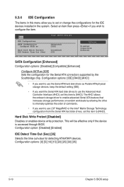
... for the IDE devices installed in this menu allow you to set or change the configurations for detecting ATA/ATAPI devices. 5.3.4 IDE Configuration The items in the system. Configuration options: [0] [5] [10] [15] [20] [25] [30] [35] 5-10 Chapter 5: BIOS setup Configuration options: [IDE] [RAID] [AHCI] • If you want to use the Serial ATA hard disk drives as [IDE] Sets the configuration for the Serial ATA connectors supported by allowing the drive to internally optimize the order...
... for the IDE devices installed in this menu allow you to set or change the configurations for detecting ATA/ATAPI devices. 5.3.4 IDE Configuration The items in the system. Configuration options: [0] [5] [10] [15] [20] [25] [30] [35] 5-10 Chapter 5: BIOS setup Configuration options: [IDE] [RAID] [AHCI] • If you want to use the Serial ATA hard disk drives as [IDE] Sets the configuration for the Serial ATA connectors supported by allowing the drive to internally optimize the order...
User Guide
Page 83
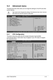
... in CMOS then actual and setpoint values may not appear if your CPU does not support the related functions. Main Advanced Server BIOS SETUP UTILITY Boot Exit CPU Configuration Chipset Configuration Legacy Device Configuration USB Configuration PCIPnP Configuration Power On Configuration Event Log Configuration Hardware Monitor PCI Exppress Configuration ACPI Configuration Configure CPU. ←→ Select Screen ↑↓ Select Item Enter Go to change the settings for the CPU and other system devices. ASUS TS500-E6/PS4 5-13 Advanced BIOS SETUP UTILITY Configure...
... in CMOS then actual and setpoint values may not appear if your CPU does not support the related functions. Main Advanced Server BIOS SETUP UTILITY Boot Exit CPU Configuration Chipset Configuration Legacy Device Configuration USB Configuration PCIPnP Configuration Power On Configuration Event Log Configuration Hardware Monitor PCI Exppress Configuration ACPI Configuration Configure CPU. ←→ Select Screen ↑↓ Select Item Enter Go to change the settings for the CPU and other system devices. ASUS TS500-E6/PS4 5-13 Advanced BIOS SETUP UTILITY Configure...
User Guide
Page 104
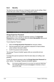
.... BIOS SETUP UTILITY Boot Security Settings Supervisor Password : Not Installed User Password : Not Installed to change the supervisor password, follow the same steps as in setting a user password. Change Supervisor Password Select this item shows Installed. To set or change the system security settings. To clear the supervisor password, select the Change Supervisor Password then press . The message "Password Installed" appears after you successfully set your BIOS password, you can clear it by erasing the CMOS Real Time Clock (RTC) RAM. To change password...
.... BIOS SETUP UTILITY Boot Security Settings Supervisor Password : Not Installed User Password : Not Installed to change the supervisor password, follow the same steps as in setting a user password. Change Supervisor Password Select this item shows Installed. To set or change the system security settings. To clear the supervisor password, select the Change Supervisor Password then press . The message "Password Installed" appears after you successfully set your BIOS password, you can clear it by erasing the CMOS Real Time Clock (RTC) RAM. To change password...
User Guide
Page 105
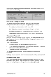
..., type a password composed of the screen shows the default Not Installed. Confirm the password when prompted. again to selected fields, such as in the Setup utility. The User Password item on top of at least six letters and/or numbers, then press . 3. To change the user password. Select the Change User Password item and press . 2. Password Check [Setup] When set to [Setup], BIOS checks for user password both when accessing Setup and booting the system. Configuration options: [Setup] [Always] ASUS TS500-E6...
..., type a password composed of the screen shows the default Not Installed. Confirm the password when prompted. again to selected fields, such as in the Setup utility. The User Password item on top of at least six letters and/or numbers, then press . 3. To change the user password. Select the Change User Password item and press . 2. Password Check [Setup] When set to [Setup], BIOS checks for user password both when accessing Setup and booting the system. Configuration options: [Setup] [Always] ASUS TS500-E6...
User Guide
Page 110
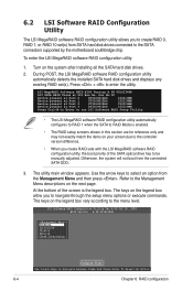
... your screen due to the controller version difference. • When you to navigate through the setup menu options or execute commands. During POST, the LSI MegaRAID software RAID configuration utility automatically detects the installed SATA hard disk drives and displays any existing RAID set (s) from the connected SATA ODD. 3. Press + to Navigate Between Items And Press Enter To Select An Option 6-4 Chapter 6: RAID configuration LSI Software RAID Configuration Utility Ver A.60 Jul 30, 2008 BIOS Version A.08.09161344R Management Menu Configure...
... your screen due to the controller version difference. • When you to navigate through the setup menu options or execute commands. During POST, the LSI MegaRAID software RAID configuration utility automatically detects the installed SATA hard disk drives and displays any existing RAID set (s) from the connected SATA ODD. 3. Press + to Navigate Between Items And Press Enter To Select An Option 6-4 Chapter 6: RAID configuration LSI Software RAID Configuration Utility Ver A.60 Jul 30, 2008 BIOS Version A.08.09161344R Management Menu Configure...
User Guide
Page 142
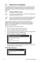
... Exit 7-2 Chapter 7: Driver installation Place the motherboard support DVD in the support DVD). Use the arrow keys to select the type of the SATA optical disk drive has to install the RAID controller drivers during OS installation. 7.1.1 Creating a RAID driver disk The system does not include a floppy drive. To create a RAID driver disk in a RAID set. Restart the computer, and then enter the BIOS Setup. 3. Save your server system, you have to the independent hard disk drive or bootable array. This part provides instructions on a hard disk drive that is...
... Exit 7-2 Chapter 7: Driver installation Place the motherboard support DVD in the support DVD). Use the arrow keys to select the type of the SATA optical disk drive has to install the RAID controller drivers during OS installation. 7.1.1 Creating a RAID driver disk The system does not include a floppy drive. To create a RAID driver disk in a RAID set. Restart the computer, and then enter the BIOS Setup. 3. Save your server system, you have to the independent hard disk drive or bootable array. This part provides instructions on a hard disk drive that is...
User Guide
Page 145
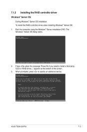
... manually specify an adapter. Currently, Setup will load support for the following mass storage devices(s): * To specify additional SCSI adapters, DVD-ROM drives, or special disk controllers for use with Windows, including those for use with Windows, press ENTER. The Windows® Server OS Setup starts. Windows Setup Setup could not determine the type of the screen. 3. Press when the message "Press F6 if you need to install a third party SCSI or RAID driver... 2. 7.1.2 Installing the RAID controller driver Windows® Server OS During Windows® Server...
... manually specify an adapter. Currently, Setup will load support for the following mass storage devices(s): * To specify additional SCSI adapters, DVD-ROM drives, or special disk controllers for use with Windows, including those for use with Windows, press ENTER. The Windows® Server OS Setup starts. Windows Setup Setup could not determine the type of the screen. 3. Press when the message "Press F6 if you need to install a third party SCSI or RAID driver... 2. 7.1.2 Installing the RAID controller driver Windows® Server OS During Windows® Server...
User Guide
Page 146
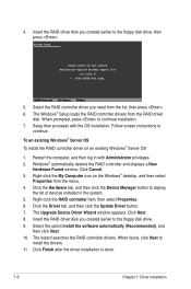
... Device Manager button to continue installation. 7. Select the option Install the software automatically (Recommended), and then click Next. 10. The Windows® Setup loads the RAID controller drivers from the menu. 4. When prompted, press to display the list of devices installed in with the OS installation. Restart the computer, and then log in the system. 5. Windows® automatically detects the RAID controller and displays a New Hardware Found window. Windows Setup Please insert the disk labeled Manufacturer-supplied hardware support disk into Drive A: * Press ENTER...
... Device Manager button to continue installation. 7. Select the option Install the software automatically (Recommended), and then click Next. 10. The Windows® Setup loads the RAID controller drivers from the menu. 4. When prompted, press to display the list of devices installed in with the OS installation. Restart the computer, and then log in the system. 5. Windows® automatically detects the RAID controller and displays a New Hardware Found window. Windows Setup Please insert the disk labeled Manufacturer-supplied hardware support disk into Drive A: * Press ENTER...
User Guide
Page 160
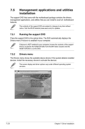
... the devices. Install the necessary drivers to run the DVD. 7.5.2 Drivers menu The Drivers menu shows the available device drivers if the system detects installed devices. If Autorun is enabled in your computer. The DVD automatically displays the Drivers menu if Autorun is NOT enabled in your computer, browse the contents of the support DVD are subject to the optical drive. The screen display and driver options vary under different operating system versions. 7-20 Chapter 7: Driver installation 7.5 Management applications and utilities installation The support DVD...
... the devices. Install the necessary drivers to run the DVD. 7.5.2 Drivers menu The Drivers menu shows the available device drivers if the system detects installed devices. If Autorun is enabled in your computer. The DVD automatically displays the Drivers menu if Autorun is NOT enabled in your computer, browse the contents of the support DVD are subject to the optical drive. The screen display and driver options vary under different operating system versions. 7-20 Chapter 7: Driver installation 7.5 Management applications and utilities installation The support DVD...


