
TS300-E3
Page 11
ASUS TS300-E3/PA4 & PS4 1- Product introduction Chapter 1 This chapter describes the general features of the barebone server, including sections on the front panel and rear panel specifications.
ASUS TS300-E3/PA4 & PS4 1- Product introduction Chapter 1 This chapter describes the general features of the barebone server, including sections on the front panel and rear panel specifications.
TS300-E3
Page 13
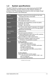
...-ECC unbuffered 667/533 MHz DDR2 memory modules Supports 256 MB up to 8 GB of system memory Dual Broadcom® BCM5721 Gigabit LAN controllers - ASUS P5MT (PA4 model) ASUS P5MT-S (PS4 model) ATX compatible form factor: 12 in x 9.6 in Northbridge: Intel® E7230 Memory Controller Hub (MCH) Southbridge: Intel® ...4/Intel® Pentium® D processor in the 775-land package, and includes the latest technologies through the chipsets embedded on the next page) ASUS TS300-E3/PA4 & PS4 1-3 1.2 System specifications The ASUS TS300-E3 is a barebone server system featuring the...
...-ECC unbuffered 667/533 MHz DDR2 memory modules Supports 256 MB up to 8 GB of system memory Dual Broadcom® BCM5721 Gigabit LAN controllers - ASUS P5MT (PA4 model) ASUS P5MT-S (PS4 model) ATX compatible form factor: 12 in x 9.6 in Northbridge: Intel® E7230 Memory Controller Hub (MCH) Southbridge: Intel® ...4/Intel® Pentium® D processor in the 775-land package, and includes the latest technologies through the chipsets embedded on the next page) ASUS TS300-E3/PA4 & PS4 1-3 1.2 System specifications The ASUS TS300-E3 is a barebone server system featuring the...
TS300-E3
Page 15
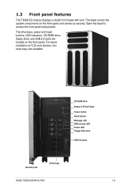
... drive Empty 5.25-inch bays Power button Reset button Message LED HDD access LED Power LED Floppy disk drive USB 2.0 ports Security lock Drive bays ASUS TS300-E3/PA4 & PS4 1-5 The bezel covers the system components on the front panel. The drive bays, power and reset buttons, LED indicators, CD-ROM drive, floppy... components. For future installation of 5.25-inch devices, two drive bays are located on the front panel and serves as security. 1.3 Front panel features The TS300-E3 chassis displays a stylish front bezel with lock.
... drive Empty 5.25-inch bays Power button Reset button Message LED HDD access LED Power LED Floppy disk drive USB 2.0 ports Security lock Drive bays ASUS TS300-E3/PA4 & PS4 1-5 The bezel covers the system components on the front panel. The drive bays, power and reset buttons, LED indicators, CD-ROM drive, floppy... components. For future installation of 5.25-inch devices, two drive bays are located on the front panel and serves as security. 1.3 Front panel features The TS300-E3 chassis displays a stylish front bezel with lock.
TS300-E3
Page 17
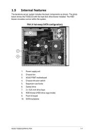
... within the system. Expansion card locks 6. Power supply unit 2. Chassis fan 3. Chassis intrusion switch 5. Optical drive 7. 2 x 5.25-inch drive bays 8. The photo below shows the TS300-E3 with the hard disk drive blower installed. 1.5 Internal features The barebone server system includes the basic components as shown. SATA backplane ASUS TS300-E3/PA4 & PS4 1-7
... within the system. Expansion card locks 6. Power supply unit 2. Chassis fan 3. Chassis intrusion switch 5. Optical drive 7. 2 x 5.25-inch drive bays 8. The photo below shows the TS300-E3 with the hard disk drive blower installed. 1.5 Internal features The barebone server system includes the basic components as shown. SATA backplane ASUS TS300-E3/PA4 & PS4 1-7

TS300-E3
Page 19
no incoming event ASMS indicates a HW monitor event Bridge board connected to the following table for the LED status description. ASUS TS300-E3/PA4 & PS4 1-9 1.6 LED information The barebone system comes with five LED indicators. Message LED (red) Drive Status LED (green/red) Drive Activity LED (green) LED ...
no incoming event ASMS indicates a HW monitor event Bridge board connected to the following table for the LED status description. ASUS TS300-E3/PA4 & PS4 1-9 1.6 LED information The barebone system comes with five LED indicators. Message LED (red) Drive Status LED (green/red) Drive Activity LED (green) LED ...
TS300-E3
Page 21
Chapter 2 This chapter lists the hardware setup procedures that you have to perform when installing or removing system components. Hardware setup ASUS TS300-E3/PA4 & PS4 2-
Chapter 2 This chapter lists the hardware setup procedures that you have to perform when installing or removing system components. Hardware setup ASUS TS300-E3/PA4 & PS4 2-

TS300-E3
Page 23
Match and insert the upper hooks and lower sliding edge of the installed components to the corresponding chassis holes and edge. 2. You may need to remove some of the cover to access the DIMM sockets and internal connectors. Drive in place. 2 3. Slide the cover toward the front until it snaps in the two screws you removed earlier to section "2.10 Removable components" for instructions. 2.1.2 Reinstalling the side cover To reinstall the side cover: 1. Refer to secure the side cover. 3 3 ASUS TS300-E3/PA4 & PS4 2-3
Match and insert the upper hooks and lower sliding edge of the installed components to the corresponding chassis holes and edge. 2. You may need to remove some of the cover to access the DIMM sockets and internal connectors. Drive in place. 2 3. Slide the cover toward the front until it snaps in the two screws you removed earlier to section "2.10 Removable components" for instructions. 2.1.2 Reinstalling the side cover To reinstall the side cover: 1. Refer to secure the side cover. 3 3 ASUS TS300-E3/PA4 & PS4 2-3
TS300-E3
Page 25
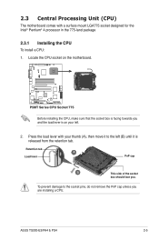
... the motherboard. ® LAN2 P5MT Series CPU Socket 775 Before installing the CPU, make sure that the socket box is released from the retention tab. ASUS TS300-E3/PA4 & PS4 2-5 Press the load lever with a surface mount LGA775 socket designed for the Intel® Pentium® 4 processor in the 775-land package 2.3.1 Installing the...
... the motherboard. ® LAN2 P5MT Series CPU Socket 775 Before installing the CPU, make sure that the socket box is released from the retention tab. ASUS TS300-E3/PA4 & PS4 2-5 Press the load lever with a surface mount LGA775 socket designed for the Intel® Pentium® 4 processor in the 775-land package 2.3.1 Installing the...
TS300-E3
Page 27
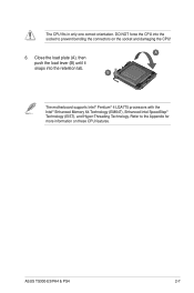
Close the load plate (A), then push the load lever (B) until it snaps into the socket to the Appendix for more information on the socket and damaging the CPU! DO NOT force the CPU into the retention tab. Refer to prevent bending the connectors on these CPU features. A 6. B The motherboard supports Intel® Pentium® 4 LGA775 processors with the Intel® Enhanced Memory 64 Technology (EM64T), Enhanced Intel SpeedStep® Technology (EIST), and Hyper-Threading Technology. ASUS TS300-E3/PA4 & PS4 2-7 The CPU fits in only one correct orientation.
Close the load plate (A), then push the load lever (B) until it snaps into the socket to the Appendix for more information on the socket and damaging the CPU! DO NOT force the CPU into the retention tab. Refer to prevent bending the connectors on these CPU features. A 6. B The motherboard supports Intel® Pentium® 4 LGA775 processors with the Intel® Enhanced Memory 64 Technology (EM64T), Enhanced Intel SpeedStep® Technology (EIST), and Hyper-Threading Technology. ASUS TS300-E3/PA4 & PS4 2-7 The CPU fits in only one correct orientation.
TS300-E3
Page 29
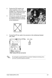
Drive the four screws into the holes in a diagonal sequence to secure the heatsink and airduct assembly to plug the connector. ASUS TS300-E3/PA4 & PS4 2-9 Hardware monitoring errors can occur if you fail to the motherboard. A B 3 3 2 3 3 B A 4. Position the CPU heatsink and airduct assembly on top of the installed CPU, ...
Drive the four screws into the holes in a diagonal sequence to secure the heatsink and airduct assembly to plug the connector. ASUS TS300-E3/PA4 & PS4 2-9 Hardware monitoring errors can occur if you fail to the motherboard. A B 3 3 2 3 3 B A 4. Position the CPU heatsink and airduct assembly on top of the installed CPU, ...
TS300-E3
Page 31
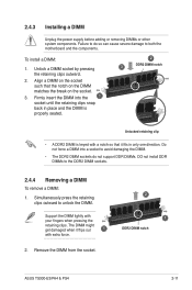
... not force a DIMM into the 1 socket until the retaining clips snap back in only one direction. Remove the DIMM from the socket. 2 1 DDR2 DIMM notch ASUS TS300-E3/PA4 & PS4 2-11 Failure to do not support DDR DIMMs. DO not install DDR DIMMs to unlock the DIMM.
... not force a DIMM into the 1 socket until the retaining clips snap back in only one direction. Remove the DIMM from the socket. 2 1 DDR2 DIMM notch ASUS TS300-E3/PA4 & PS4 2-11 Failure to do not support DDR DIMMs. DO not install DDR DIMMs to unlock the DIMM.

TS300-E3
Page 33
Hinge-like tabs from the holes on the right side of the front panel to completely detach the front panel assembly from the chassis. Do not use too much force when removing the front panel assembly. 4. Unhook the hinge-like tab ASUS TS300-E3/PA4 & PS4 2-13
Hinge-like tabs from the holes on the right side of the front panel to completely detach the front panel assembly from the chassis. Do not use too much force when removing the front panel assembly. 4. Unhook the hinge-like tab ASUS TS300-E3/PA4 & PS4 2-13
TS300-E3
Page 35
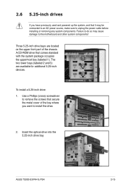
... that secure the metal cover of the chassis. Three 5.25-inch drive bays are available for additional 5.25-inch 2 devices. 3 To install a 5.25-inch drive: 1. ASUS TS300-E3/PA4 & PS4 2-15 Use a Phillips (cross) screwdriver to unplug the power cable before installing or removing any system components.
... that secure the metal cover of the chassis. Three 5.25-inch drive bays are available for additional 5.25-inch 2 devices. 3 To install a 5.25-inch drive: 1. ASUS TS300-E3/PA4 & PS4 2-15 Use a Phillips (cross) screwdriver to unplug the power cable before installing or removing any system components.
TS300-E3
Page 37
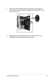
ASUS TS300-E3/PA4 & PS4 2-17 Refer to section "2.5.2 Reinstalling the front panel assembly" for instructions. On the front panel assembly, detach the plastic bay cover opposite the 5.25-inch drive that you installed by pressing the two hooked tabs on each side of the bay cover. 8. Reinstall the front panel assembly when done. 7.
ASUS TS300-E3/PA4 & PS4 2-17 Refer to section "2.5.2 Reinstalling the front panel assembly" for instructions. On the front panel assembly, detach the plastic bay cover opposite the 5.25-inch drive that you installed by pressing the two hooked tabs on each side of the bay cover. 8. Reinstall the front panel assembly when done. 7.

TS300-E3
Page 39
Push the tray lever until just a small fraction of the bay until it with the bay edge. Carefully insert drive tray and push it all the way to the drive tray, and secure it clicks, and secures the drive tray in place. ASUS TS300-E3/PA4 & PS4 2-19 The drive tray is correctly placed when its front edge aligns with four screws. 6. 5. Place a SATA or an SCA SCSI hard disk to the depth of the tray edge protrudes. 7.
Push the tray lever until just a small fraction of the bay until it with the bay edge. Carefully insert drive tray and push it all the way to the drive tray, and secure it clicks, and secures the drive tray in place. ASUS TS300-E3/PA4 & PS4 2-19 The drive tray is correctly placed when its front edge aligns with four screws. 6. 5. Place a SATA or an SCA SCSI hard disk to the depth of the tray edge protrudes. 7.

TS300-E3
Page 41
ASUS TS300-E3/PA4 & PS4 2-21 Remove the screw that secures the metal bracket to unplug the power cord before installing or removing expansion cards. Align the card golden &#...
ASUS TS300-E3/PA4 & PS4 2-21 Remove the screw that secures the metal bracket to unplug the power cord before installing or removing expansion cards. Align the card golden &#...

TS300-E3
Page 43
... ICH7R SATA2 SATA1 5 FRNT_FAN2 SCSIA1 Intel 6702 PXH 11 12 FLOPPY1 PRI_IDE1 30.5cm (12in) 13 Standard cables connected to Chapter 4 for PS4 Model only) ASUS TS300-E3/PA4 & PS4 2-23 SMBus connector 2. 4-pin 12V power 8. Floppy disk drive 6. SCSI connector (for detailed information on the connectors. Front USB cable 4. Primary IDE cable 13...
... ICH7R SATA2 SATA1 5 FRNT_FAN2 SCSIA1 Intel 6702 PXH 11 12 FLOPPY1 PRI_IDE1 30.5cm (12in) 13 Standard cables connected to Chapter 4 for PS4 Model only) ASUS TS300-E3/PA4 & PS4 2-23 SMBus connector 2. 4-pin 12V power 8. Floppy disk drive 6. SCSI connector (for detailed information on the connectors. Front USB cable 4. Primary IDE cable 13...
TS300-E3
Page 45
... CR2032 3V Lithium Cell CMOS Power BUZZ1 USBPW34 USB34 PANEL1 Intel 6702 PXH FLOPPY1 PRI_IDE1 30.5cm (12in) SATA RAID controller SATA4 SATA2 SATA1 SATA3 ASUS TS300-E3/PA4 & PS4 2-25
... CR2032 3V Lithium Cell CMOS Power BUZZ1 USBPW34 USB34 PANEL1 Intel 6702 PXH FLOPPY1 PRI_IDE1 30.5cm (12in) SATA RAID controller SATA4 SATA2 SATA1 SATA3 ASUS TS300-E3/PA4 & PS4 2-25
TS300-E3
Page 47
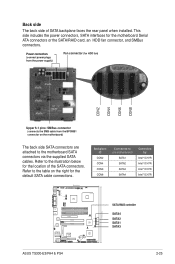
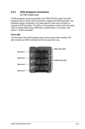
... backplane faces the front panel when installed. See section "1.6 LED information." Disk drive 1 Disk drive 2 Disk drive 3 Disk drive 4 HDD status LEDs HDD activity LEDs ASUS TS300-E3/PA4 & PS4 2-27 This side includes four SCSI connectors for the hot swap drive trays. 2.9.3 SCSI backplane connections (in PS4 model only) A SCSI backplane comes pre...
... backplane faces the front panel when installed. See section "1.6 LED information." Disk drive 1 Disk drive 2 Disk drive 3 Disk drive 4 HDD status LEDs HDD activity LEDs ASUS TS300-E3/PA4 & PS4 2-27 This side includes four SCSI connectors for the hot swap drive trays. 2.9.3 SCSI backplane connections (in PS4 model only) A SCSI backplane comes pre...

TS300-E3
Page 49
The picture below shows the location of the SCSI backplanes allows you to the following tables for the jumper settings and the appropriate ID# for each SCSI HDD bay. J1 setting (1-3 shorted, 2-4 shorted) Device Drive Bay 1 Drive Bay 2 Drive Bay 3 Drive Bay 4 GEM SAF-TE SCSI ID# ID0 ID1 ID2 ID3 ID15 (SCSI channel-0) ASUS TS300-E3/PA4 & PS4 2-29 SCSI backplane jumper settings and HDD ID assignments The 6-pin jumper J1 on each of jumper J1 with pins 1-3 and 2-4 shorted. Refer to define your desired SCSI configuration.
The picture below shows the location of the SCSI backplanes allows you to the following tables for the jumper settings and the appropriate ID# for each SCSI HDD bay. J1 setting (1-3 shorted, 2-4 shorted) Device Drive Bay 1 Drive Bay 2 Drive Bay 3 Drive Bay 4 GEM SAF-TE SCSI ID# ID0 ID1 ID2 ID3 ID15 (SCSI channel-0) ASUS TS300-E3/PA4 & PS4 2-29 SCSI backplane jumper settings and HDD ID assignments The 6-pin jumper J1 on each of jumper J1 with pins 1-3 and 2-4 shorted. Refer to define your desired SCSI configuration.


