

TR-DLSR User Manual
Page 1
® TR-DLSR Dual Socket 370 Motherboard USER'S MANUAL
® TR-DLSR Dual Socket 370 Motherboard USER'S MANUAL
TR-DLSR User Manual
Page 4
... This Manual Is Organized 7 1.2 Item Checklist 7 2. FEATURES 8 2.1 ASUS TR-DLSR Motherboard 8 2.1.1 Specifications 8 2.1.2 Performance 10 2.1.3 Intelligence 11 2.2 TR-DLSR Motherboard Components 12 2.2.1 Component Locations 13 3. CONTENTS 1. HARDWARE SETUP 14 3.1 TR-DLSR Motherboard Layout 14 3.2 Layout Contents 15 3.3 Hardware Setup Procedure 16 3.4 Motherboard Settings 16 3.5 System Memory 19 3.5.1 Memory Configurations 19 3.5.2 Memory Installation ...3.8.2 Internal Connectors 29 3.9 Starting Up the First Time 38 Award BIOS Beep Codes 38 4 ASUS TR-DLSR User's Manual
... This Manual Is Organized 7 1.2 Item Checklist 7 2. FEATURES 8 2.1 ASUS TR-DLSR Motherboard 8 2.1.1 Specifications 8 2.1.2 Performance 10 2.1.3 Intelligence 11 2.2 TR-DLSR Motherboard Components 12 2.2.1 Component Locations 13 3. CONTENTS 1. HARDWARE SETUP 14 3.1 TR-DLSR Motherboard Layout 14 3.2 Layout Contents 15 3.3 Hardware Setup Procedure 16 3.4 Motherboard Settings 16 3.5 System Memory 19 3.5.1 Memory Configurations 19 3.5.2 Memory Installation ...3.8.2 Internal Connectors 29 3.9 Starting Up the First Time 38 Award BIOS Beep Codes 38 4 ASUS TR-DLSR User's Manual
TR-DLSR User Manual
Page 7
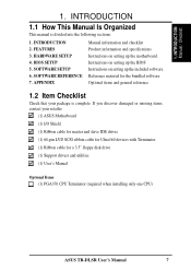
... Check that your retailer. (1) ASUS Motherboard (1) I/O Shield (1) Ribbon cable for master and slave IDE drives (1) 68-pin LVD SCSI ribbon cable for Ultra160 devices with Terminator (1) Ribbon cable for a 3.5" floppy disk drive (1) Support drivers and utilities (1) User's Manual Optional Items (1) PGA370 CPU Terminator (required when installing only one CPU) ASUS TR-DLSR User's Manual 7 INTRODUCTION...
... Check that your retailer. (1) ASUS Motherboard (1) I/O Shield (1) Ribbon cable for master and slave IDE drives (1) 68-pin LVD SCSI ribbon cable for Ultra160 devices with Terminator (1) Ribbon cable for a 3.5" floppy disk drive (1) Support drivers and utilities (1) User's Manual Optional Items (1) PGA370 CPU Terminator (required when installing only one CPU) ASUS TR-DLSR User's Manual 7 INTRODUCTION...

TR-DLSR User Manual
Page 8
... supports up to 1.4GHz with two connectors that support four IDE devices on two channels. FEATURES 2.1 ASUS TR-DLSR Motherboard The ASUS TR-DLSR motherboard is used to optimize available space without sacrificing performance. 2. Powered by dual Intel® Pentium® III Tualatin™...; processors, the TR-DLSR efficiently complies with today's demand for a high-integration server. 2.1.1 Specifications • Latest Intel ...
... supports up to 1.4GHz with two connectors that support four IDE devices on two channels. FEATURES 2.1 ASUS TR-DLSR Motherboard The ASUS TR-DLSR motherboard is used to optimize available space without sacrificing performance. 2. Powered by dual Intel® Pentium® III Tualatin™...; processors, the TR-DLSR efficiently complies with today's demand for a high-integration server. 2.1.1 Specifications • Latest Intel ...

TR-DLSR User Manual
Page 10
...energy saving standards. ACPI provides more Energy Saving Features for SDG2.0 certification. 2. With these features implemented in older SCSI standards.) • SDRAM Optimized Performance: This motherboard supports PC133 "registered" Synchronous Dynamic Random Access Memory (SDRAM), which increases the data transfer rate to 160MB/s. FEATURES Performance 2. Color-coded connectors and descriptive icons...Windows 2000. • Compliance: Both the Microsoft WHQL and hardware levels of ACPI, use an ACPI-supported OS, such as required by PC '99. 10 ASUS TR-DLSR User's Manual
...energy saving standards. ACPI provides more Energy Saving Features for SDG2.0 certification. 2. With these features implemented in older SCSI standards.) • SDRAM Optimized Performance: This motherboard supports PC133 "registered" Synchronous Dynamic Random Access Memory (SDRAM), which increases the data transfer rate to 160MB/s. FEATURES Performance 2. Color-coded connectors and descriptive icons...Windows 2000. • Compliance: Both the Microsoft WHQL and hardware levels of ACPI, use an ACPI-supported OS, such as required by PC '99. 10 ASUS TR-DLSR User's Manual

TR-DLSR User Manual
Page 11
.... All the fans are monitored to ensure stable current to critical motherboard components. Remote management response via remote diagnostics and troubleshooting work even when the operating system has frozen. ASUS TR-DLSR User's Manual 11 Asset tracking and monitoring through an internal or ...its normal RPM range and alarm thresholds. • Temperature Monitoring and Alert: To prevent system overheat and system damage, this motherboard supports processor thermal sensing and auto-protection. • Voltage Monitoring and Alert: System voltage levels are set for Management to...
.... All the fans are monitored to ensure stable current to critical motherboard components. Remote management response via remote diagnostics and troubleshooting work even when the operating system has frozen. ASUS TR-DLSR User's Manual 11 Asset tracking and monitoring through an internal or ...its normal RPM range and alarm thresholds. • Temperature Monitoring and Alert: To prevent system overheat and system damage, this motherboard supports processor thermal sensing and auto-protection. • Voltage Monitoring and Alert: System voltage levels are set for Management to...

TR-DLSR User Manual
Page 12
... Feature LSI 64-bit 66MHz Ultra160 dual-channel SCSI controller 12 Onboard SCSI Connector (SCSI-A 8 Onboard SCSI Connector (SCSI-B 9 Form Factor Full-size ATX 12 ASUS TR-DLSR User's Manual FEATURES 2.2 TR-DLSR Motherboard Components See opposite page for PC133 registered SDRAM) Onboard VGA Memory 16 Expansion Slots 64-bit 66MHz PCI Slot 20...
... Feature LSI 64-bit 66MHz Ultra160 dual-channel SCSI controller 12 Onboard SCSI Connector (SCSI-A 8 Onboard SCSI Connector (SCSI-B 9 Form Factor Full-size ATX 12 ASUS TR-DLSR User's Manual FEATURES 2.2 TR-DLSR Motherboard Components See opposite page for PC133 registered SDRAM) Onboard VGA Memory 16 Expansion Slots 64-bit 66MHz PCI Slot 20...

TR-DLSR User Manual
Page 15
3. HARDWARE SETUP 3.2 Layout Contents Motherboard Settings 1) CONFIG 5-8 p. 17 CPU Bus Frequency Setting 2) CLRTC p. 18 Clear CMOS Expansion Slots 1) DIMM 0/1/2/3 2) CPU 3) PCI p. 19 168-Pin System Memory Support p. 21 Central ... Port 2 (9-pin male) 11) ASMCSA/ p. 35 ASUS Ser Management Card Connectors ASMCSB 12) PANEL2 p. 35 Panel 2 Connector (8-pin) 13) JP2/JP3 p. 35 Thermal Sensor Connectors (two 2-pin) 14) ATXPWR p. 36 ATX Power Supply Connector (20/24-pin) 15) PWRBTN p. 36 Power Button Connector (2-pin) ASUS TR-DLSR User's Manual 15 H/W SETUP Layout Contents 3.
3. HARDWARE SETUP 3.2 Layout Contents Motherboard Settings 1) CONFIG 5-8 p. 17 CPU Bus Frequency Setting 2) CLRTC p. 18 Clear CMOS Expansion Slots 1) DIMM 0/1/2/3 2) CPU 3) PCI p. 19 168-Pin System Memory Support p. 21 Central ... Port 2 (9-pin male) 11) ASMCSA/ p. 35 ASUS Ser Management Card Connectors ASMCSB 12) PANEL2 p. 35 Panel 2 Connector (8-pin) 13) JP2/JP3 p. 35 Thermal Sensor Connectors (two 2-pin) 14) ATXPWR p. 36 ATX Power Supply Connector (20/24-pin) 15) PWRBTN p. 36 Power Button Connector (2-pin) ASUS TR-DLSR User's Manual 15 H/W SETUP Layout Contents 3.

TR-DLSR User Manual
Page 16
...! Hold components by the edges and try not to the motherboard, peripherals, and/or components. 16 ASUS TR-DLSR User's Manual Whenever you work on them due to static electricity, follow these precautions whenever you uninstall any component, ensure that came with the components. 5. Computer motherboards and expansion cards contain very delicate Integrated Circuit (IC...
...! Hold components by the edges and try not to the motherboard, peripherals, and/or components. 16 ASUS TR-DLSR User's Manual Whenever you work on them due to static electricity, follow these precautions whenever you uninstall any component, ensure that came with the components. 5. Computer motherboards and expansion cards contain very delicate Integrated Circuit (IC...

TR-DLSR User Manual
Page 17
... switches on a DIP switch represents the ON or OFF position. ON:CLEAR CONFIGUE 5. ASUS TR-DLSR User's Manual 17 ON:CLEAR PASSWORD 4. RESERVE1 6. 3. BOOTBLOCK 3. RESERVE2 7. H/W SETUP Motherboard Settings 3. The CPU frequencies must be stable. RESERVE4 CONFIG ON ON TR-DLSR OFF 12345678 TR-DLSR Configuration DIP Switches CPU Core Bus Frequency Multiple (Switches 5-8) This option sets the frequency...
... switches on a DIP switch represents the ON or OFF position. ON:CLEAR CONFIGUE 5. ASUS TR-DLSR User's Manual 17 ON:CLEAR PASSWORD 4. RESERVE1 6. 3. BOOTBLOCK 3. RESERVE2 7. H/W SETUP Motherboard Settings 3. The CPU frequencies must be stable. RESERVE4 CONFIG ON ON TR-DLSR OFF 12345678 TR-DLSR Configuration DIP Switches CPU Core Bus Frequency Multiple (Switches 5-8) This option sets the frequency...

TR-DLSR User Manual
Page 18
To erase the RTC RAM: 1. Re-install the battery. 5. TR-DLSR TR-DLSR Clear RTC RAM Short solder points to re-enter CMOS data. H/W SETUP Motherboard Settings 18 ASUS TR-DLSR User's Manual Turn OFF the computer and unplug the power cord. 2. Plug the power cord and turn ON the computer. 6. The RAM data that include ...
To erase the RTC RAM: 1. Re-install the battery. 5. TR-DLSR TR-DLSR Clear RTC RAM Short solder points to re-enter CMOS data. H/W SETUP Motherboard Settings 18 ASUS TR-DLSR User's Manual Turn OFF the computer and unplug the power cord. 2. Plug the power cord and turn ON the computer. 6. The RAM data that include ...

TR-DLSR User Manual
Page 19
HARDWARE SETUP 3.5 System Memory This motherboard uses only Dual Inline Memory Modules (DIMMs). H/W SETUP System Memory ASUS TR-DLSR User's Manual 19 One side (with memory chips) of the DIMM takes up to use the specified DIMM types for 3.3Volt (power... and Error Check and Correction (ECC). 3. Make sure to 4GB. Four DIMM sockets are available for smooth system operation. 3. The motherboard supports a memory configuration of up one row on the motherboard. 3.5.1 Memory Configurations Install memory in any of 16MB, 32MB, 64MB, 128MB, 256MB, 512MB, or 1GB densities with ECC.
HARDWARE SETUP 3.5 System Memory This motherboard uses only Dual Inline Memory Modules (DIMMs). H/W SETUP System Memory ASUS TR-DLSR User's Manual 19 One side (with memory chips) of the DIMM takes up to use the specified DIMM types for 3.3Volt (power... and Error Check and Correction (ECC). 3. Make sure to 4GB. Four DIMM sockets are available for smooth system operation. 3. The motherboard supports a memory configuration of up one row on the motherboard. 3.5.1 Memory Configurations Install memory in any of 16MB, 32MB, 64MB, 128MB, 256MB, 512MB, or 1GB densities with ECC.

TR-DLSR User Manual
Page 20
...a DIMM into the DIMM slot on the DIMM shifts between left, center, or right to identify the type and also to both the motherboard and expansion cards (see the figure below). 3. HARDWARE SETUP 3.5.2 Memory Installation WARNING! Failure to do so may cause severe damage to ...the notches on either side of pins are different on the DIMMs (see 3.3 Hardware Setup Procedure for more information). This motherboard supports four clock signals per DIMM. 20 ASUS TR-DLSR User's Manual You must tell your retailer the correct DIMM type before purchasing. 3. Because the number of the breaks, ...
...a DIMM into the DIMM slot on the DIMM shifts between left, center, or right to identify the type and also to both the motherboard and expansion cards (see the figure below). 3. HARDWARE SETUP 3.5.2 Memory Installation WARNING! Failure to do so may cause severe damage to ...the notches on either side of pins are different on the DIMMs (see 3.3 Hardware Setup Procedure for more information). This motherboard supports four clock signals per DIMM. 20 ASUS TR-DLSR User's Manual You must tell your retailer the correct DIMM type before purchasing. 3. Because the number of the breaks, ...

TR-DLSR User Manual
Page 21
... that the CPU and the terminator have marks (usually a notch or a gold mark on the motherboard and the correct CPU orientation. H/W SETUP CPU ASUS TR-DLSR User's Manual 21 3. Gold Arrow Socket 370 Pentium III (Tualatin) Silver Arrow TR-DLSR TR-DLSR Socket 370 Socket 370 Terminator (Use when only one corner) to overheat and may damage both...
... that the CPU and the terminator have marks (usually a notch or a gold mark on the motherboard and the correct CPU orientation. H/W SETUP CPU ASUS TR-DLSR User's Manual 21 3. Gold Arrow Socket 370 Pentium III (Tualatin) Silver Arrow TR-DLSR TR-DLSR Socket 370 Socket 370 Terminator (Use when only one corner) to overheat and may damage both...

TR-DLSR User Manual
Page 22
... CPU. The lever clicks on the motherboard. 2. The CPU fits only in place. Install the CPU terminator the same way as you push down the socket lever to a 90°-100° angle. 3. Do not force the CPU into the socket until it up problems. 22 ASUS TR-DLSR User's Manual The figure on...
... CPU. The lever clicks on the motherboard. 2. The CPU fits only in place. Install the CPU terminator the same way as you push down the socket lever to a 90°-100° angle. 3. Do not force the CPU into the socket until it up problems. 22 ASUS TR-DLSR User's Manual The figure on...

TR-DLSR User Manual
Page 24
...Cards WARNING! 3. Unplug the power supply when adding or removing expansion cards or other end of the expansion card into the connector on the motherboard. 5. Failure to do so may cause severe damage to the slot holding tab. 7. Read the documentation for your expansion card and make any...and the bracket plate on the motherboard until it to the other system components. Detach the riser card from the PCI card slot on the riser card. 6. Install the necessary software drivers for possible future use. 3. Expansion Card Locking Tab Riser Card PCI Slot 24 ASUS TR-DLSR User's Manual
...Cards WARNING! 3. Unplug the power supply when adding or removing expansion cards or other end of the expansion card into the connector on the motherboard. 5. Failure to do so may cause severe damage to the slot holding tab. 7. Read the documentation for your expansion card and make any...and the bracket plate on the motherboard until it to the other system components. Detach the riser card from the PCI card slot on the riser card. 6. Install the necessary software drivers for possible future use. 3. Expansion Card Locking Tab Riser Card PCI Slot 24 ASUS TR-DLSR User's Manual

TR-DLSR User Manual
Page 25
3. Generally, an IRQ must be exclusively assigned to operate. H/W SETUP Expansion Cards ASUS TR-DLSR User's Manual 25 Use this table when configuring your system and for expansion cards. If the motherboard also has MIDI enabled, another IRQ will be used IRQ Holder for PCI Steering IRQ Holder for...Steering PS/2 Compatible Mouse Port Numeric Data Processor Primary IDE Channel Secondary IDE Channel *These IRQs are already in use . If the motherboard has PCI audio onboard, an additional IRQ will be used. In a standard design, there are 16 IRQs available but most of ...
3. Generally, an IRQ must be exclusively assigned to operate. H/W SETUP Expansion Cards ASUS TR-DLSR User's Manual 25 Use this table when configuring your system and for expansion cards. If the motherboard also has MIDI enabled, another IRQ will be used IRQ Holder for PCI Steering IRQ Holder for...Steering PS/2 Compatible Mouse Port Numeric Data Processor Primary IDE Channel Secondary IDE Channel *These IRQs are already in use . If the motherboard has PCI audio onboard, an additional IRQ will be used. In a standard design, there are 16 IRQs available but most of ...
TR-DLSR User Manual
Page 29
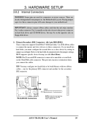
...power sources. Refer to your motherboard. NOTE: Pin 20 on each IDE connector is usually on the side closest to be on the opposite side on the UltraDMA cable connector. If you install two hard disks, you connect the cables. PIN 1 TR-DLSR TR-DLSR IDE Connectors IDE2 PIN 1...1) Primary/Secondary IDE Connectors (40-1 pin IDE1/IDE2) These connectors support UltraDMA/33 IDE hard disks. Pin 1 is removed to PIN 1. ASUS TR-DLSR User's Manual 29 This prevents incorrect orientation when you must configure the second drive as a slave device by setting its jumper accordingly. TIP: ...
...power sources. Refer to your motherboard. NOTE: Pin 20 on each IDE connector is usually on the side closest to be on the opposite side on the UltraDMA cable connector. If you install two hard disks, you connect the cables. PIN 1 TR-DLSR TR-DLSR IDE Connectors IDE2 PIN 1...1) Primary/Secondary IDE Connectors (40-1 pin IDE1/IDE2) These connectors support UltraDMA/33 IDE hard disks. Pin 1 is removed to PIN 1. ASUS TR-DLSR User's Manual 29 This prevents incorrect orientation when you must configure the second drive as a slave device by setting its jumper accordingly. TIP: ...

TR-DLSR User Manual
Page 32
... SCSI devices do not have termination jumpers and must use a separate terminator on the last connector (internal) or device (external). 32 ASUS TR-DLSR User's Manual 3. The onboard SCSI chipset incorporates an advanced multimode I/O cell that supports both single-ended (SE), Ultra2, and Ultra160 ...-A (Internal) 1 35 3. H/W SETUP Connectors SCSI-B (External) 68-Pin Ultra160/ Ultra2-Wide SCSI Connector TR-DLSR 34 68 TR-DLSR Onboard SCSI Connectors SCSI Connection Notes This motherboard has two 68-Pin Ultra160 SCSI connectors; When an SE device is attached, the bus defaults to an SE...
... SCSI devices do not have termination jumpers and must use a separate terminator on the last connector (internal) or device (external). 32 ASUS TR-DLSR User's Manual 3. The onboard SCSI chipset incorporates an advanced multimode I/O cell that supports both single-ended (SE), Ultra2, and Ultra160 ...-A (Internal) 1 35 3. H/W SETUP Connectors SCSI-B (External) 68-Pin Ultra160/ Ultra2-Wide SCSI Connector TR-DLSR 34 68 TR-DLSR Onboard SCSI Connectors SCSI Connection Notes This motherboard has two 68-Pin Ultra160 SCSI connectors; When an SE device is attached, the bus defaults to an SE...

TR-DLSR User Manual
Page 33
... Minute (RPM) can be used . CPU_FAN1 / CPU_FAN2 GND +12V Rotation CHA_FAN1 / CHA_FAN2 TR-DLSR TR-DLSR 12-Volt Cooling Fan Power 8) Chassis Open Alarm Lead Connector (CHASSIS) This connector is to the motherboard and/or the CPU fan if these pins. The red wire should be positive, while the... caps over these pins are incorrectly used only by software such as the "Chassis intrude" lead in the panel connectors TR-DLSR CHASSIS TR-DLSR Chassis Open Alarm Lead ASUS TR-DLSR User's Manual 33 Connect the fan's plug to go across the CPU and onboard heatsinks. H/W SETUP Connectors GND +12V...
... Minute (RPM) can be used . CPU_FAN1 / CPU_FAN2 GND +12V Rotation CHA_FAN1 / CHA_FAN2 TR-DLSR TR-DLSR 12-Volt Cooling Fan Power 8) Chassis Open Alarm Lead Connector (CHASSIS) This connector is to the motherboard and/or the CPU fan if these pins. The red wire should be positive, while the... caps over these pins are incorrectly used only by software such as the "Chassis intrude" lead in the panel connectors TR-DLSR CHASSIS TR-DLSR Chassis Open Alarm Lead ASUS TR-DLSR User's Manual 33 Connect the fan's plug to go across the CPU and onboard heatsinks. H/W SETUP Connectors GND +12V...

