User Guide
Page 2
...ANY DEFECT OR ERROR IN THIS MANUAL OR PRODUCT. ASUS ASSUMES NO RESPONSIBILITY OR LIABILITY FOR ANY ERRORS OR INACCURACIES THAT MAY APPEAR IN THIS MANUAL, INCLUDING THE PRODUCTS AND SOFTWARE DESCRIBED IN IT. ii SPECIFICATIONS AND INFORMATION CONTAINED IN THIS MANUAL ARE FURNISHED FOR ...INFORMATIONAL USE ONLY, AND ARE SUBJECT TO CHANGE AT ANY TIME WITHOUT NOTICE, AND SHOULD NOT BE CONSTRUED AS A COMMITMENT BY ASUS. All Rights Reserved. ASUS PROVIDES THIS MANUAL "AS IS...
...ANY DEFECT OR ERROR IN THIS MANUAL OR PRODUCT. ASUS ASSUMES NO RESPONSIBILITY OR LIABILITY FOR ANY ERRORS OR INACCURACIES THAT MAY APPEAR IN THIS MANUAL, INCLUDING THE PRODUCTS AND SOFTWARE DESCRIBED IN IT. ii SPECIFICATIONS AND INFORMATION CONTAINED IN THIS MANUAL ARE FURNISHED FOR ...INFORMATIONAL USE ONLY, AND ARE SUBJECT TO CHANGE AT ANY TIME WITHOUT NOTICE, AND SHOULD NOT BE CONSTRUED AS A COMMITMENT BY ASUS. All Rights Reserved. ASUS PROVIDES THIS MANUAL "AS IS...
User Guide
Page 8
... information and installation instructions about the motherboard that comes with hardware knowledge of the ASUS T2-PH1. Chapter 5: BIOS information This chapter tells how to install components in the system. 3. Appendix The Appendix includes the power supply unit specification for experienced users and integrators with the system. Chapter 1: System introduction This chapter... CD. 4 . About this system. This guide is organized This guide contains the following parts: 1. Chapter 4: Motherboard information This chapter gives information about the ASUS T2-PH1 barebone system.
... information and installation instructions about the motherboard that comes with hardware knowledge of the ASUS T2-PH1. Chapter 5: BIOS information This chapter tells how to install components in the system. 3. Appendix The Appendix includes the power supply unit specification for experienced users and integrators with the system. Chapter 1: System introduction This chapter... CD. 4 . About this system. This guide is organized This guide contains the following parts: 1. Chapter 4: Motherboard information This chapter gives information about the ASUS T2-PH1 barebone system.
User Guide
Page 17
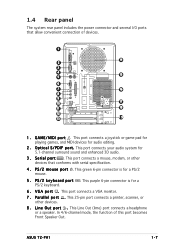
.... 7 . This purple 6-pin connector is for a PS/2 keyboard. 6 . S e r i a l p o r t . G A M E / M I D I F p o r t . 1.4 Rear panel The system rear panel includes the power connector and several I/O ports that conforms with serial specification. 4 . ASUS T2-PH1 1-7
.... 7 . This purple 6-pin connector is for a PS/2 keyboard. 6 . S e r i a l p o r t . G A M E / M I D I F p o r t . 1.4 Rear panel The system rear panel includes the power connector and several I/O ports that conforms with serial specification. 4 . ASUS T2-PH1 1-7
User Guide
Page 33
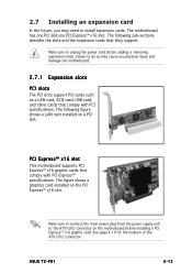
ASUS T2-PH1 2-13 The following figure shows a LAN card installed on the PCI Express™ x16 slot. See page 4-10 for the location of the ATX12V2 connector. ... motherboard before adding or removing expansion cards. PCI Express™ x16 slot This motherboard supports PCI Express™ x16 graphic cards that comply with PCI specifications. Make sure to connect the 4-pin power plug from the power supply unit to install expansion cards. The following sub-sections describe the slots and...
ASUS T2-PH1 2-13 The following figure shows a LAN card installed on the PCI Express™ x16 slot. See page 4-10 for the location of the ATX12V2 connector. ... motherboard before adding or removing expansion cards. PCI Express™ x16 slot This motherboard supports PCI Express™ x16 graphic cards that comply with PCI specifications. Make sure to connect the 4-pin power plug from the power supply unit to install expansion cards. The following sub-sections describe the slots and...
User Guide
Page 44
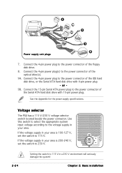
.... Chapter 2: Basic installation or - 9B. Use this switch to select the appropriate system input voltage according to 115 V. See the Appendix for the power supply specifications. If the voltage supply in your area is 200-240 V, set the switch to the voltage supply in your area is 100-127 V, set the...
.... Chapter 2: Basic installation or - 9B. Use this switch to select the appropriate system input voltage according to 115 V. See the Appendix for the power supply specifications. If the voltage supply in your area is 200-240 V, set the switch to the voltage supply in your area is 100-127 V, set the...
User Guide
Page 85
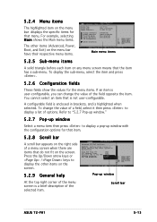
... IDE Master Fourth IDE Master IDE Configuration : [ST320410A] : [ASUS CD-S520/A] : [Not Detected] : [Not Detected] System Information Main menu items 5.2.5 Sub-menu items A solid triangle before each item on the menu bar displays the specific items for that menu. To display the sub-menu, select the... item and press . 5.2.6 Configuration fields These fields show the values for that item. 5.2.8 Scroll bar A scroll bar appears on the right side of options. Scroll bar ASUS T2-PH1 5-13 Press the Up...
... IDE Master Fourth IDE Master IDE Configuration : [ST320410A] : [ASUS CD-S520/A] : [Not Detected] : [Not Detected] System Information Main menu items 5.2.5 Sub-menu items A solid triangle before each item on the menu bar displays the specific items for that menu. To display the sub-menu, select the... item and press . 5.2.6 Configuration fields These fields show the values for that item. 5.2.8 Scroll bar A scroll bar appears on the right side of options. Scroll bar ASUS T2-PH1 5-13 Press the Up...
User Guide
Page 87
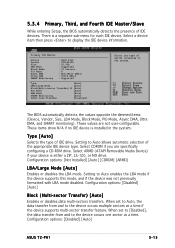
... not user-configurable. Configuration options: [Disabled] [Auto] Block (Multi-sector Transfer) [Auto] Enables or disables data multi-sectors transfers. Configuration options: [Disabled] [Auto] ASUS T2-PH1 5-15 Primary IDE Master Device Vendor Size LBA Mode Block Mode PIO Mode Async DMA Ultra DMA SMART Monitoring : Hard Disk : ST320410A : 20.0GB : Supported...opposite the dimmed items (Device, Vendor, Size, LBA Mode, Block Mode, PIO Mode, Async DMA, Ultra DMA, and SMART monitoring). These values are specifically configuring a CD-ROM drive. Setting to display the IDE device information.
... not user-configurable. Configuration options: [Disabled] [Auto] Block (Multi-sector Transfer) [Auto] Enables or disables data multi-sectors transfers. Configuration options: [Disabled] [Auto] ASUS T2-PH1 5-15 Primary IDE Master Device Vendor Size LBA Mode Block Mode PIO Mode Async DMA Ultra DMA SMART Monitoring : Hard Disk : ST320410A : 20.0GB : Supported...opposite the dimmed items (Device, Vendor, Size, LBA Mode, Block Mode, PIO Mode, Async DMA, Ultra DMA, and SMART monitoring). These values are specifically configuring a CD-ROM drive. Setting to display the IDE device information.
User Guide
Page 90
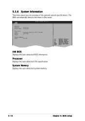
5.3.6 System Information This menu gives you an overview of the general system specifications. Processor Displays the auto-detected CPU specification. System Memory Displays the auto-detected system memory. 5-18 Chapter 5: BIOS setup The BIOS automatically detects the items in this menu. AMIBIOS Version : 08.00.10 Build Date : 01/14/05 Processor Type : Genuine Intel(R) CPU 3.20 GHz Speed : 3200 MHz Count : 1 System Memory Size : 248 MB AMI BIOS Displays the auto-detected BIOS information.
5.3.6 System Information This menu gives you an overview of the general system specifications. Processor Displays the auto-detected CPU specification. System Memory Displays the auto-detected system memory. 5-18 Chapter 5: BIOS setup The BIOS automatically detects the items in this menu. AMIBIOS Version : 08.00.10 Build Date : 01/14/05 Processor Type : Genuine Intel(R) CPU 3.20 GHz Speed : 3200 MHz Count : 1 System Memory Size : 248 MB AMI BIOS Displays the auto-detected BIOS information.
User Guide
Page 100
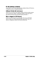
... PCI/PnP devices. Configuration options: [Auto] [PCI Slot1] [PCI Slot2] [PCI Slot3] [PCI Slot4] [PCI Slot5] [PCI Slot6 ] IRQ-xx assigned to [PCI Device], the specific IRQ is reserved for use PCI bus mastering when reading/writing to IDE devices. Configuration options: [Disabled] [Enabled] OffBoard PCI/ISA IDE Card [Auto] Allows...
... PCI/PnP devices. Configuration options: [Auto] [PCI Slot1] [PCI Slot2] [PCI Slot3] [PCI Slot4] [PCI Slot5] [PCI Slot6 ] IRQ-xx assigned to [PCI Device], the specific IRQ is reserved for use PCI bus mastering when reading/writing to IDE devices. Configuration options: [Disabled] [Enabled] OffBoard PCI/ISA IDE Card [Auto] Allows...
User Guide
Page 101
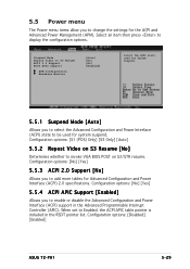
... [S3 Only] [Auto] 5.5.2 Repost Video on S3 Resume [No] Determines whether to add more tables for Advanced Configuration and Power Interface (ACPI) 2.0 specifications. Configuration options: [No] [Yes] 5.5.3 ACPI 2.0 Support [No] Allows you to invoke VGA BIOS POST on S3 Resume ACPI 2.0 Support ACPI APIC ...allow you to be used for system suspend. Suspend Mode Repost Video on S3/STR resume. Configuration options: [Disabled] [Enabled] ASUS T2-PH1 5-29 Select an item then press to enable or disable the Advanced Configuration and Power Interface (ACPI) support in the RSDT pointer ...
... [S3 Only] [Auto] 5.5.2 Repost Video on S3 Resume [No] Determines whether to add more tables for Advanced Configuration and Power Interface (ACPI) 2.0 specifications. Configuration options: [No] [Yes] 5.5.3 ACPI 2.0 Support [No] Allows you to invoke VGA BIOS POST on S3 Resume ACPI 2.0 Support ACPI APIC ...allow you to be used for system suspend. Suspend Mode Repost Video on S3/STR resume. Configuration options: [Disabled] [Enabled] ASUS T2-PH1 5-29 Select an item then press to enable or disable the Advanced Configuration and Power Interface (ACPI) support in the RSDT pointer ...
User Guide
Page 102
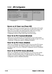
... the AC power loss. Configuration options: [Disabled] [Enabled] Power On By PCI/PCIE Devices [Disabled] When set to [Enabled], this parameter allows you to use specific keys on the keyboard to Power Off, the system goes into off or on the +5VSB lead. Restore on AC Power Loss [Power Off] When...
... the AC power loss. Configuration options: [Disabled] [Enabled] Power On By PCI/PCIE Devices [Disabled] When set to [Enabled], this parameter allows you to use specific keys on the keyboard to Power Off, the system goes into off or on the +5VSB lead. Restore on AC Power Loss [Power Off] When...
User Guide
Page 104
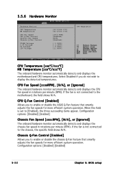
...specific field shows N/A. Configuration options: [Disabled] [Enabled] Chassis Fan Speed [xxxxRPM], [N/A], or [Ignored] The onboard hardware monitor automatically detects and displays the chassis fan speed in rotations per minute (RPM). If the fan is not connected to enable or disable the ASUS...Enabled] [N/A] [Enabled] [ 1.320V] [ 3.345V] [ 5.094V] [11.880V] CPU Temperature CPU Temperature [xxxºC/xxxºF] MB Temperature [xxxºC/xxxºF] The onboard hardware monitor automatically detects and displays the motherboard and CPU temperatures. Chassis Q-Fan Control [Enabled] ...
...specific field shows N/A. Configuration options: [Disabled] [Enabled] Chassis Fan Speed [xxxxRPM], [N/A], or [Ignored] The onboard hardware monitor automatically detects and displays the chassis fan speed in rotations per minute (RPM). If the fan is not connected to enable or disable the ASUS...Enabled] [N/A] [Enabled] [ 1.320V] [ 3.345V] [ 5.094V] [11.880V] CPU Temperature CPU Temperature [xxxºC/xxxºF] MB Temperature [xxxºC/xxxºF] The onboard hardware monitor automatically detects and displays the motherboard and CPU temperatures. Chassis Q-Fan Control [Enabled] ...
User Guide
Page 111
Appendix The Appendix includes the power supply unit specification for this system. MODE ASUS T2-PH1 Appendix
Appendix The Appendix includes the power supply unit specification for this system. MODE ASUS T2-PH1 Appendix
User Guide
Page 112
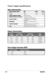
... mVp-p 60 mVp-p Over-Voltage Protection (OVP) Output Voltage +3.3V +5V +12V Maximum Voltage 4.6V 6.5V 15.6V A-2 Appendix at 115 Vac 3 A max. Power supply specifications Input characteristics Input Voltage Range Range 1 Range 2 Input Frequency Range Maximum Input AC Current Inrush Current Efficiency Current Harmonic EPA Min Nom 90 V 115 V 180...
... mVp-p 60 mVp-p Over-Voltage Protection (OVP) Output Voltage +3.3V +5V +12V Maximum Voltage 4.6V 6.5V 15.6V A-2 Appendix at 115 Vac 3 A max. Power supply specifications Input characteristics Input Voltage Range Range 1 Range 2 Input Frequency Range Maximum Input AC Current Inrush Current Efficiency Current Harmonic EPA Min Nom 90 V 115 V 180...