User Guide
Page 7
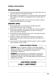
... documentation that the power cables for the devices are unplugged before relocating the system. • When adding or removing devices to or from connectors, slots, sockets and circuitry. • Avoid dust, humidity, and temperature extremes. Place the product on a stable surface. • If you detect any area where it by the...
... documentation that the power cables for the devices are unplugged before relocating the system. • When adding or removing devices to or from connectors, slots, sockets and circuitry. • Avoid dust, humidity, and temperature extremes. Place the product on a stable surface. • If you detect any area where it by the...
User Guide
Page 19
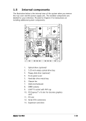
... 12 1. DIMM sockets 9. LGA775 socket with PnP cap 10. Floppy disk drive (optional) 4. Proceed to Chapter 2 for your reference. Hard disk drive metal tray 6. Chassis fan 7. PCI Express™ x16 slot for discrete graphics card 11. PCI slot 12. Serial ATA connectors 13. Front panel cover 5. ASUS motherboard 8. Expansion card slots ASUS T2-PH1 1-9 1.5 Internal components...
... 12 1. DIMM sockets 9. LGA775 socket with PnP cap 10. Floppy disk drive (optional) 4. Proceed to Chapter 2 for your reference. Hard disk drive metal tray 6. Chassis fan 7. PCI Express™ x16 slot for discrete graphics card 11. PCI slot 12. Serial ATA connectors 13. Front panel cover 5. ASUS motherboard 8. Expansion card slots ASUS T2-PH1 1-9 1.5 Internal components...
User Guide
Page 25
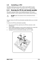
D O N O T replace the proprietary CPU fan and heatsink with a surface mount LGA775 socket designed for the Intel® Pentium® 4 processor in the 775-land package. 2.5.1 Removing the CPU fan and heatsink assembly The system package ... 1. Disconnect the CPU fan cable from the CPU fan connector on the motherboard. 2. Using a Phillips screwdriver, remove and set it aside. 2 2 2 2 1 3 ASUS T2-PH1 2-5 2.5 Installing a CPU The ASUS motherboard comes with other models. Carefully lift the fan and heatsink assembly, and set aside the four screws that secure the fan and heatsink...
D O N O T replace the proprietary CPU fan and heatsink with a surface mount LGA775 socket designed for the Intel® Pentium® 4 processor in the 775-land package. 2.5.1 Removing the CPU fan and heatsink assembly The system package ... 1. Disconnect the CPU fan cable from the CPU fan connector on the motherboard. 2. Using a Phillips screwdriver, remove and set it aside. 2 2 2 2 1 3 ASUS T2-PH1 2-5 2.5 Installing a CPU The ASUS motherboard comes with other models. Carefully lift the fan and heatsink assembly, and set aside the four screws that secure the fan and heatsink...
User Guide
Page 26
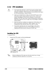
... PnP cap is shipment/ transit-related. • Keep the cap after installing the motherboard. ASUS will shoulder the cost of the PnP cap. Locate the CPU socket on your motherboard to the PnP cap/socket contacts/motherboard components. ASUS will process Return Merchandise Authorization (RMA) requests only if the motherboard comes with installation instructions...
... PnP cap is shipment/ transit-related. • Keep the cap after installing the motherboard. ASUS will shoulder the cost of the PnP cap. Locate the CPU socket on your motherboard to the PnP cap/socket contacts/motherboard components. ASUS will process Return Merchandise Authorization (RMA) requests only if the motherboard comes with installation instructions...
User Guide
Page 27
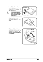
To prevent damage to a 135º angle. Retention tab A B Load lever 3 4. Lift the load plate with your thumb and forefinger to remove (B). 2. Lift the load lever in the direction of the arrow to the socket pins, do not remove the PnP cap unless you are installing a CPU. 3. PnP cap Load plate B A ASUS T2-PH1 2-7 Press the load lever with your thumb (A), then move it to the left (B) until it is released from the load plate window to a 100º angle (A), then push the PnP cap from the retention tab.
To prevent damage to a 135º angle. Retention tab A B Load lever 3 4. Lift the load plate with your thumb and forefinger to remove (B). 2. Lift the load lever in the direction of the arrow to the socket pins, do not remove the PnP cap unless you are installing a CPU. 3. PnP cap Load plate B A ASUS T2-PH1 2-7 Press the load lever with your thumb (A), then move it to the left (B) until it is released from the load plate window to a 100º angle (A), then push the PnP cap from the retention tab.

User Guide
Page 28
... key should fit into the retention tab. Apply Thermal Interface Material on the bottom-left corner of the socket. Gold triangle mark Alignment key 6. 5. Position the CPU over the socket, making sure that the gold triangle is on the CPU before reinstalling the heatsink and fan assembly. B 7. If it gets into your...
... key should fit into the retention tab. Apply Thermal Interface Material on the bottom-left corner of the socket. Gold triangle mark Alignment key 6. 5. Position the CPU over the socket, making sure that the gold triangle is on the CPU before reinstalling the heatsink and fan assembly. B 7. If it gets into your...
User Guide
Page 30
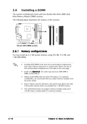
Use any of the sockets: 184-pin DDR DIMM sockets 2.6.1 Memory configurations You may cause memory sizing error or system boot failure. For optimum compatibility, we recommend that you obtain memory ... installed two 1 GB DDR memory. • This motherboard does not support memory modules made up to 2 GB system memory using 256 MB, 512 MB, and 1 GB DDR DIMMs. • Installing DDR DIMMS other than the recommended configurations may install up of 128...) DDR DIMM in DIMM_A and DIMM_B. • Always install DIMMs with two Double Data Rate (DDR) Dual Inline Memory Module (DIMM) sockets.
Use any of the sockets: 184-pin DDR DIMM sockets 2.6.1 Memory configurations You may cause memory sizing error or system boot failure. For optimum compatibility, we recommend that you obtain memory ... installed two 1 GB DDR memory. • This motherboard does not support memory modules made up to 2 GB system memory using 256 MB, 512 MB, and 1 GB DDR DIMMs. • Installing DDR DIMMS other than the recommended configurations may install up of 128...) DDR DIMM in DIMM_A and DIMM_B. • Always install DIMMs with two Double Data Rate (DDR) Dual Inline Memory Module (DIMM) sockets.
User Guide
Page 31
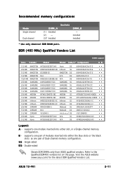
... support Size Vendor Model Brand Side/s* Component AB 512 MB 256 MB 512 MB 512 MB 1024 MB 256 MB 256 MB 256 MB 512 MB 256 MB 512 MB 256 MB 512 MB 256 MB 512 MB 512 MB 256 MB 512 MB KINGSTON KINGSTON KINGSTON KINGSTON KINGSTON SAMSUNG SAMSUNG SAMSUNG SAMSUNG MICRON...ASUS qualified vendors. Single-sided D S - Visit the ASUS website (www.asus.com) for the latest DDR Qualified Vendors List. Refer to the Qualified DDR400 vendors list on this page. ASUS T2-PH1 2-11 Recommended memory configurations Mode Single-channel Dual-channel DIMM_A (1) Installed (2) - (3)* Installed Sockets...
... support Size Vendor Model Brand Side/s* Component AB 512 MB 256 MB 512 MB 512 MB 1024 MB 256 MB 256 MB 256 MB 512 MB 256 MB 512 MB 256 MB 512 MB 256 MB 512 MB 512 MB 256 MB 512 MB KINGSTON KINGSTON KINGSTON KINGSTON KINGSTON SAMSUNG SAMSUNG SAMSUNG SAMSUNG MICRON...ASUS qualified vendors. Single-sided D S - Visit the ASUS website (www.asus.com) for the latest DDR Qualified Vendors List. Refer to the Qualified DDR400 vendors list on this page. ASUS T2-PH1 2-11 Recommended memory configurations Mode Single-channel Dual-channel DIMM_A (1) Installed (2) - (3)* Installed Sockets...
User Guide
Page 32
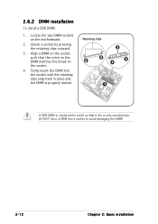
2.6.2 DIMM installation To install a DDR DIMM: 1. Align a DIMM on the socket such that it fits in place and the DIMM is keyed with a notch so that the notch on the DIMM matches the break on the motherboard. 2. DO NOT force a DIMM into the socket until the retaining clips snap back in only one direction. Firmly insert the DIMM into a socket to avoid damaging the DIMM! 2-12 Chapter 2: Basic installation Unlock a socket by pressing the retaining clips outward. 3. Locate the two DIMM sockets on the socket. 4. Retaining clips 2 2 3 4 4 1 A DDR DIMM is properly seated.
2.6.2 DIMM installation To install a DDR DIMM: 1. Align a DIMM on the socket such that it fits in place and the DIMM is keyed with a notch so that the notch on the DIMM matches the break on the motherboard. 2. DO NOT force a DIMM into the socket until the retaining clips snap back in only one direction. Firmly insert the DIMM into a socket to avoid damaging the DIMM! 2-12 Chapter 2: Basic installation Unlock a socket by pressing the retaining clips outward. 3. Locate the two DIMM sockets on the socket. 4. Retaining clips 2 2 3 4 4 1 A DDR DIMM is properly seated.
