
User Guide
Page 3
... 2-3 2.4 Removing the power supply 2-4 2.5 Installing a CPU 2-5 2.5.1 Removing the CPU fan and heatsink assembly ....... 2-5 2.5.2 CPU installation 2-6 2.5.3 Reinstalling the CPU fan and heatsink assembly ..... 2-9 2.6 Installing a DIMM 2-10 2.6.1 Memory configurations 2-10 2.6.2 DIMM installation 2-12 2.7 Installing an expansion card 2-13 2.7.1 Expansion slots 2-13 2.7.2 Expansion card installation 2-14 2.8 Installing an optical drive 2-16 2.9 Installing a floppy disk...
... 2-3 2.4 Removing the power supply 2-4 2.5 Installing a CPU 2-5 2.5.1 Removing the CPU fan and heatsink assembly ....... 2-5 2.5.2 CPU installation 2-6 2.5.3 Reinstalling the CPU fan and heatsink assembly ..... 2-9 2.6 Installing a DIMM 2-10 2.6.1 Memory configurations 2-10 2.6.2 DIMM installation 2-12 2.7 Installing an expansion card 2-13 2.7.1 Expansion slots 2-13 2.7.2 Expansion card installation 2-14 2.8 Installing an optical drive 2-16 2.9 Installing a floppy disk...
User Guide
Page 12
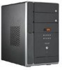
... introduction The ASUS T2-PH1 is designed for the sophisticated. The system comes in a stylish mini-tower casing, and powered by the ASUS motherboard that supports the Intel® Pentium® 4 processor in -one barebone system with 800 MHz FSB and up to 2 GB system memory. With these and many more, the T2-PH1 definitely delivers the...
... introduction The ASUS T2-PH1 is designed for the sophisticated. The system comes in a stylish mini-tower casing, and powered by the ASUS motherboard that supports the Intel® Pentium® 4 processor in -one barebone system with 800 MHz FSB and up to 2 GB system memory. With these and many more, the T2-PH1 definitely delivers the...
User Guide
Page 15
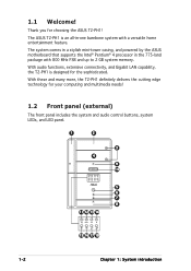
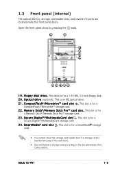
O p t i c a l d r i v e (optional). This slot is for a CompactFlash®/Microdrive™ storage card. 2 2 . This drive is for a 1.44 MB, 3.5-inch floppy disk. 2 0 . M e m o r y S t i c k®/ M e m o r y S t i c k P r o ™ c a r d s l o t . This slot is an IDE optical drive. 2 1 . F l o p p y d...card. • You cannot close the storage card reader door if a storage card is for a Memory Stick®/Memory Stick Pro™ storage card. 2 3 . 1.3 Front panel (internal) The optical drive(s), storage... with it. S m a r t M e d i a® c a r d s l o t . ASUS T2-PH1 1-5
O p t i c a l d r i v e (optional). This slot is for a CompactFlash®/Microdrive™ storage card. 2 2 . This drive is for a 1.44 MB, 3.5-inch floppy disk. 2 0 . M e m o r y S t i c k®/ M e m o r y S t i c k P r o ™ c a r d s l o t . This slot is an IDE optical drive. 2 1 . F l o p p y d...card. • You cannot close the storage card reader door if a storage card is for a Memory Stick®/Memory Stick Pro™ storage card. 2 3 . 1.3 Front panel (internal) The optical drive(s), storage... with it. S m a r t M e d i a® c a r d s l o t . ASUS T2-PH1 1-5
User Guide
Page 22
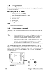
... pad or in the bag that came with an onboard standby power LED. This LED lights up to install in the system. DDR Dual Inline Memory Module (DIMM) 3. Hard disk drive 5. 2.1 Preparation Before you proceed, make sure that the standby power LED is ON, in sleep mode or in soft-off...
... pad or in the bag that came with an onboard standby power LED. This LED lights up to install in the system. DDR Dual Inline Memory Module (DIMM) 3. Hard disk drive 5. 2.1 Preparation Before you proceed, make sure that the standby power LED is ON, in sleep mode or in soft-off...
User Guide
Page 30
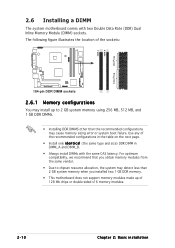
... DIMM_B. • Always install DIMMs with two Double Data Rate (DDR) Dual Inline Memory Module (DIMM) sockets. The following figure illustrates the location of 128 Mb chips or double-sided x16 memory modules. 2-10 Chapter 2: Basic installation For optimum compatibility, we recommend that you obtain...to chipset resource allocation, the system may detect less than 2 GB system memory when you installed two 1 GB DDR memory. • This motherboard does not support memory modules made up to 2 GB system memory using 256 MB, 512 MB, and 1 GB DDR DIMMs. • Installing DDR DIMMS other than the...
... DIMM_B. • Always install DIMMs with two Double Data Rate (DDR) Dual Inline Memory Module (DIMM) sockets. The following figure illustrates the location of 128 Mb chips or double-sided x16 memory modules. 2-10 Chapter 2: Basic installation For optimum compatibility, we recommend that you obtain...to chipset resource allocation, the system may detect less than 2 GB system memory when you installed two 1 GB DDR memory. • This motherboard does not support memory modules made up to 2 GB system memory using 256 MB, 512 MB, and 1 GB DDR DIMMs. • Installing DDR DIMMS other than the...
User Guide
Page 31
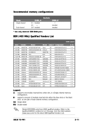
...ASUS qualified vendors. ASUS T2-PH1 2-11 Visit the ASUS website (www.asus.com) for the latest DDR Qualified Vendors List. DDR (400 MHz) Qualified Vendors List DIMM support Size Vendor Model Brand Side/s* Component AB 512 MB 256 MB 512 MB 512 MB 1024 MB 256 MB 256 MB 256 MB 512 MB 256 MB 512 MB 256 MB 512 MB 256 MB 512 MB 512 MB 256 MB 512 MB... DDR400 vendors list on this page. supports one module inserted into either slot, in a Single-channel memory configuration. supports one pair of modules inserted into either the blue slots or the black slots as one pair of Dual-...
...ASUS qualified vendors. ASUS T2-PH1 2-11 Visit the ASUS website (www.asus.com) for the latest DDR Qualified Vendors List. DDR (400 MHz) Qualified Vendors List DIMM support Size Vendor Model Brand Side/s* Component AB 512 MB 256 MB 512 MB 512 MB 1024 MB 256 MB 256 MB 256 MB 512 MB 256 MB 512 MB 256 MB 512 MB 256 MB 512 MB 512 MB 256 MB 512 MB... DDR400 vendors list on this page. supports one module inserted into either slot, in a Single-channel memory configuration. supports one pair of modules inserted into either the blue slots or the black slots as one pair of Dual-...
User Guide
Page 61
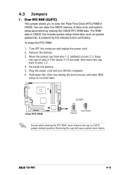
...You can clear the CMOS memory of date, time, and system setup parameters by the onboard button cell battery. Turn OFF the computer and unplug the power cord. 2. Re-install the battery. 5. Remove the battery. 3. Removing the cap will cause system boot failure. The RAM data in CMOS. Hold... during the boot process and enter BIOS setup to pins 2-3. ASUS T2-PH1 4-3 Move the jumper cap from pins 1-2 (default) to re-enter data. ® Clear RTC RAM CLRTC 2 1 Normal (Default) 3 2 Clear CMOS Except when clearing the RTC RAM, never remove the cap on pins 2-3 for about 5-10 seconds...
...You can clear the CMOS memory of date, time, and system setup parameters by the onboard button cell battery. Turn OFF the computer and unplug the power cord. 2. Re-install the battery. 5. Remove the battery. 3. Removing the cap will cause system boot failure. The RAM data in CMOS. Hold... during the boot process and enter BIOS setup to pins 2-3. ASUS T2-PH1 4-3 Move the jumper cap from pins 1-2 (default) to re-enter data. ® Clear RTC RAM CLRTC 2 1 Normal (Default) 3 2 Clear CMOS Except when clearing the RTC RAM, never remove the cap on pins 2-3 for about 5-10 seconds...
User Guide
Page 90
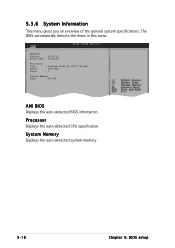
The BIOS automatically detects the items in this menu. Processor Displays the auto-detected CPU specification. System Memory Displays the auto-detected system memory. 5-18 Chapter 5: BIOS setup AMIBIOS Version : 08.00.10 Build Date : 01/14/05 Processor Type : Genuine Intel(R) CPU 3.20 GHz Speed : 3200 MHz Count : 1 System Memory Size : 248 MB AMI BIOS Displays the auto-detected BIOS information. 5.3.6 System Information This menu gives you an overview of the general system specifications.
The BIOS automatically detects the items in this menu. Processor Displays the auto-detected CPU specification. System Memory Displays the auto-detected system memory. 5-18 Chapter 5: BIOS setup AMIBIOS Version : 08.00.10 Build Date : 01/14/05 Processor Type : Genuine Intel(R) CPU 3.20 GHz Speed : 3200 MHz Count : 1 System Memory Size : 248 MB AMI BIOS Displays the auto-detected BIOS information. 5.3.6 System Information This menu gives you an overview of the general system specifications.
User Guide
Page 95
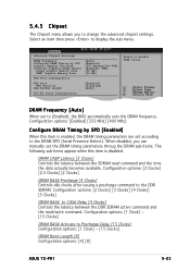
...] ~ [15 Clocks] DRAM Burst Length [8] Configuration options: [4] [8] ASUS T2-PH1 5-23 Configuration options: [Enabled] [333 MHz] [400 MHz] Configure DRAM Timing by SPD Graphic Adapter Priority Internal Graphics Mode Select Fixed Graphic Memory Size DVMT Graphic Memory Size [Auto] [Enabled] [PCI Express/Int-VGA] [Enabled, 8MB] [32 MB] [32 MB] PEG Port Configuration PEG Port PEG Force...
...] ~ [15 Clocks] DRAM Burst Length [8] Configuration options: [4] [8] ASUS T2-PH1 5-23 Configuration options: [Enabled] [333 MHz] [400 MHz] Configure DRAM Timing by SPD Graphic Adapter Priority Internal Graphics Mode Select Fixed Graphic Memory Size DVMT Graphic Memory Size [Auto] [Enabled] [PCI Express/Int-VGA] [Enabled, 8MB] [32 MB] [32 MB] PEG Port Configuration PEG Port PEG Force...
User Guide
Page 96
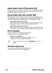
...] [Enabled, 4 MB] [Enabled, 8 MB] [Enabled, 16 MB] [Enabled, 32 MB] Fixed Graphic Memory Size [32 MB] Allows selection of the size of graphic memory used by DVMT mode. Configuration options: [Auto] [Long] [Short] 5-24 Chapter 5: BIOS setup Configuration options: [0 MB] [32 MB] [64 MB] [128 MB] [224 MB] PEG Port [Enabled... Express/ PCI] [PCI/PCI Express] [PCI/Int-VGA] Internal Graphics Mode Select [Enabled, 8MB] Allows selection of the amount of graphic memory used by the internal graphics device. Configuration options: [Disabled] [Enabled] The above item appears only when the P E G P o r...
...] [Enabled, 4 MB] [Enabled, 8 MB] [Enabled, 16 MB] [Enabled, 32 MB] Fixed Graphic Memory Size [32 MB] Allows selection of the size of graphic memory used by DVMT mode. Configuration options: [Auto] [Long] [Short] 5-24 Chapter 5: BIOS setup Configuration options: [0 MB] [32 MB] [64 MB] [128 MB] [224 MB] PEG Port [Enabled... Express/ PCI] [PCI/PCI Express] [PCI/Int-VGA] Internal Graphics Mode Select [Enabled, 8MB] Allows selection of the amount of graphic memory used by the internal graphics device. Configuration options: [Disabled] [Enabled] The above item appears only when the P E G P o r...
User Guide
Page 99
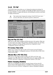
... setting IRQ and DMA channel resources for either PCI/PnP or legacy ISA devices, and setting the memory size block for boot if your system has a Plug and Play operating system. Configuration options: [Disabled] [Enabled] ASUS T2-PH1 5-27 When set to PCI VGA card if the card requests for an IRQ. 5.4.6 PCI PnP...
... setting IRQ and DMA channel resources for either PCI/PnP or legacy ISA devices, and setting the memory size block for boot if your system has a Plug and Play operating system. Configuration options: [Disabled] [Enabled] ASUS T2-PH1 5-27 When set to PCI VGA card if the card requests for an IRQ. 5.4.6 PCI PnP...

