T2-PE1 English User Manual E2151
Page 3
... the power supply unit 2-4 2.5 Installing a CPU 2-5 2.5.1 Removing the CPU fan and heatsink assembly ....... 2-5 2.5.2 CPU installation 2-6 2.5.3 Reinstalling the CPU fan and heatsink assembly ..... 2-9 2.6 Installing a DIMM 2-10 2.6.1 Memory configurations 2-10 2.6.2 DIMM installation 2-12 2.7 Installing an expansion card 2-13 2.7.1 Expansion slots 2-13 2.7.2 Expansion card installation 2-14 2.7.3 Configuring an expansion card 2-15 2.8 Installing an optical...
... the power supply unit 2-4 2.5 Installing a CPU 2-5 2.5.1 Removing the CPU fan and heatsink assembly ....... 2-5 2.5.2 CPU installation 2-6 2.5.3 Reinstalling the CPU fan and heatsink assembly ..... 2-9 2.6 Installing a DIMM 2-10 2.6.1 Memory configurations 2-10 2.6.2 DIMM installation 2-12 2.7 Installing an expansion card 2-13 2.7.1 Expansion slots 2-13 2.7.2 Expansion card installation 2-14 2.7.3 Configuring an expansion card 2-15 2.8 Installing an optical...
T2-PE1 English User Manual E2151
Page 12
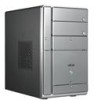
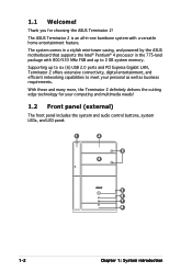
... the system and audio control buttons, system LEDs, and LED panel. 1 2 3 4 5 6 7 8 1-2 Chapter 1: System introduction The ASUS Terminator 2 is an all-in the 775-land package with a versatile home entertainment feature. With these and many more, the Terminator 2 definitely delivers...ASUS motherboard that supports the Intel® Pentium® 4 processor in -one barebone system with 800/533 MHz FSB and up to six (6) USB 2.0 ports and PCI Express Gigabit LAN, Terminator 2 offers extensive connectivity, digital entertainment, and efficient networking capabilities to 2 GB system memory...
... the system and audio control buttons, system LEDs, and LED panel. 1 2 3 4 5 6 7 8 1-2 Chapter 1: System introduction The ASUS Terminator 2 is an all-in the 775-land package with a versatile home entertainment feature. With these and many more, the Terminator 2 definitely delivers...ASUS motherboard that supports the Intel® Pentium® 4 processor in -one barebone system with 800/533 MHz FSB and up to six (6) USB 2.0 ports and PCI Express Gigabit LAN, Terminator 2 offers extensive connectivity, digital entertainment, and efficient networking capabilities to 2 GB system memory...
T2-PE1 English User Manual E2151
Page 20
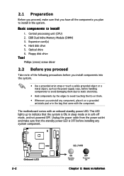
... Off Chapter 2: Basic installation Basic components to indicate that came with an onboard standby power LED. This LED lights up to install 1. DDR Dual Inline Memory Module (DIMM) 3. The motherboard comes with the component.
... Off Chapter 2: Basic installation Basic components to indicate that came with an onboard standby power LED. This LED lights up to install 1. DDR Dual Inline Memory Module (DIMM) 3. The motherboard comes with the component.

T2-PE1 English User Manual E2151
Page 28
...system motherboard comes with the same CAS latency. Use any of the sockets: ¤ 184-pin DDR DIMM sockets 2.6.1 Memory configurations You may install up to 2 GB system memory using 256 MB, 512 MB, and 1 GB DDR DIMMs. • Installing DDR DIMMS other than the recommended configurations.... • Install only i d e n t i c a l (the same type and size) DDR DIMM in the table on the onboard VGA shared memory setting. 2-10 Chapter 2: Basic installation The following figure illustrates the location of the recommended configurations in DIMM1 and DIMM2. • Always install DIMMs with two...
...system motherboard comes with the same CAS latency. Use any of the sockets: ¤ 184-pin DDR DIMM sockets 2.6.1 Memory configurations You may install up to 2 GB system memory using 256 MB, 512 MB, and 1 GB DDR DIMMs. • Installing DDR DIMMS other than the recommended configurations.... • Install only i d e n t i c a l (the same type and size) DDR DIMM in the table on the onboard VGA shared memory setting. 2-10 Chapter 2: Basic installation The following figure illustrates the location of the recommended configurations in DIMM1 and DIMM2. • Always install DIMMs with two...
T2-PE1 English User Manual E2151
Page 29
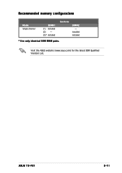
ASUS T2-PE1 2-11 Visit the ASUS website (www.asus.com) for the latest DDR Qualified Vendors List. Installed Installed * Use only identical DDR DIMM pairs. Recommended memory configurations Mode Single-channel DIMM1 (1) Installed (2) - (3)* Installed Sockets DIMM2 -
ASUS T2-PE1 2-11 Visit the ASUS website (www.asus.com) for the latest DDR Qualified Vendors List. Installed Installed * Use only identical DDR DIMM pairs. Recommended memory configurations Mode Single-channel DIMM1 (1) Installed (2) - (3)* Installed Sockets DIMM2 -
T2-PE1 English User Manual E2151
Page 56
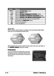
... also turns red. Button Function Opens the C o n f i g u r a t i o n window Opens the R e p o r t window Opens the D e s k t o p M a n a g e m e n t I n t e r f a c e window Opens the P e r i p h e r a l C o m p o n e n t I n t e r c o n n e c t window Opens the W i n d o w s M a n a g e m e n t I n s t r u m e n t a t i o n window Opens the hard disk drive, memory, CPU usage window Shows/Hides the P r e f e r e n c e section Minimizes the application Closes the application Sensor alert When a system sensor detects a problem, the main window right handle...
... also turns red. Button Function Opens the C o n f i g u r a t i o n window Opens the R e p o r t window Opens the D e s k t o p M a n a g e m e n t I n t e r f a c e window Opens the P e r i p h e r a l C o m p o n e n t I n t e r c o n n e c t window Opens the W i n d o w s M a n a g e m e n t I n s t r u m e n t a t i o n window Opens the hard disk drive, memory, CPU usage window Shows/Hides the P r e f e r e n c e section Minimizes the application Closes the application Sensor alert When a system sensor detects a problem, the main window right handle...
T2-PE1 English User Manual E2151
Page 59
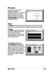
.... PCI browser Click to display the Usage browser. This browser provides information on the PCI devices installed on the CPU, hard disk drive space, and memory usage. Click the plus sign (+) before the P C I I n f o r m a t i o n item to display the information on the right panel. CPU usage The C P U tab displays real-time CPU ... The U s a g e browser displays real-time information on your system. Hard disk drive space usage The H a r d D i s k tab displays the used (blue) and the available HDD space. ASUS T2-PE1 3-15 The left panel of the tab lists all logical drives.
.... PCI browser Click to display the Usage browser. This browser provides information on the PCI devices installed on the CPU, hard disk drive space, and memory usage. Click the plus sign (+) before the P C I I n f o r m a t i o n item to display the information on the right panel. CPU usage The C P U tab displays real-time CPU ... The U s a g e browser displays real-time information on your system. Hard disk drive space usage The H a r d D i s k tab displays the used (blue) and the available HDD space. ASUS T2-PE1 3-15 The left panel of the tab lists all logical drives.

T2-PE1 English User Manual E2151
Page 60
... your saved configuration Saves your configuration 3-16 Chapter 3: Starting up The pie chart at the bottom of the window represents the used and available physical memory. Memory usage The Memory tab shows both used (blue) and the available physical...
... your saved configuration Saves your configuration 3-16 Chapter 3: Starting up The pie chart at the bottom of the window represents the used and available physical memory. Memory usage The Memory tab shows both used (blue) and the available physical...

T2-PE1 English User Manual E2151
Page 63
The RAM data in CMOS. Remove the battery. 3. Turn OFF the computer and unplug the power cord. 2. Reinstall the battery. 5. ASUS T2-PE1 4-3 4.3 Jumper Clear RTC RAM (CLRTC) This jumper allows you to clear the Real Time Clock (RTC) RAM in CMOS, that include system setup information such ... the cap on pins 2-3 for about 5-10 seconds, then move the cap back to pins 2-3. To erase the RTC RAM: 1. You can clear the CMOS memory of date, time, and system setup parameters by the onboard button cell battery. Removing the cap will cause system boot failure.
The RAM data in CMOS. Remove the battery. 3. Turn OFF the computer and unplug the power cord. 2. Reinstall the battery. 5. ASUS T2-PE1 4-3 4.3 Jumper Clear RTC RAM (CLRTC) This jumper allows you to clear the Real Time Clock (RTC) RAM in CMOS, that include system setup information such ... the cap on pins 2-3 for about 5-10 seconds, then move the cap back to pins 2-3. To erase the RTC RAM: 1. You can clear the CMOS memory of date, time, and system setup parameters by the onboard button cell battery. Removing the cap will cause system boot failure.
T2-PE1 English User Manual E2151
Page 87
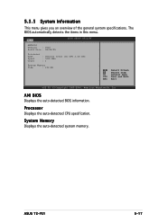
.../05 Processor Type Speed Count : Genuine Intel (R) CPU 3.20 GHz : 3200 MHz : 1 System Memory Size : 192 MB Select Screen Select Item F1 General Help F10 Save and Exit ESC Exit v02.58 (C)Copyright 1985-2004, American Megatrends, Inc. ASUS T2-PE1 5-17 5.3.5 System Information This menu gives you an overview of the general system...
.../05 Processor Type Speed Count : Genuine Intel (R) CPU 3.20 GHz : 3200 MHz : 1 System Memory Size : 192 MB Select Screen Select Item F1 General Help F10 Save and Exit ESC Exit v02.58 (C)Copyright 1985-2004, American Megatrends, Inc. ASUS T2-PE1 5-17 5.3.5 System Information This menu gives you an overview of the general system...

T2-PE1 English User Manual E2151
Page 90
...Inc. Configuration options: [Auto] [Manual] The following items appear if the M e m o r y T i m i n g item is set the memory voltage. Valid values: [0 CLOCK] [2 CLOCKS] [3 CLOCKS]... [8 CLOCKS] 5-20 Chapter 5: BIOS setup Boot Graphics Adapter Priority [PEG/IGD] Allows selection of ... to use as primary boot device. Select Screen Select Item +- Configuration options: [2.94V] [2.85V] [2.73V] [2.65V] Memory Timing [Auto] Allows you to set the memory timing manually, or allows the BIOS to configure it automatically. CAS Timing [Disabled] Configuration options: [Disabled] [1 Clock] ...
...Inc. Configuration options: [Auto] [Manual] The following items appear if the M e m o r y T i m i n g item is set the memory voltage. Valid values: [0 CLOCK] [2 CLOCKS] [3 CLOCKS]... [8 CLOCKS] 5-20 Chapter 5: BIOS setup Boot Graphics Adapter Priority [PEG/IGD] Allows selection of ... to use as primary boot device. Select Screen Select Item +- Configuration options: [2.94V] [2.85V] [2.73V] [2.65V] Memory Timing [Auto] Allows you to set the memory timing manually, or allows the BIOS to configure it automatically. CAS Timing [Disabled] Configuration options: [Disabled] [1 Clock] ...

T2-PE1 English User Manual E2151
Page 93
...onboard LAN. The menu includes setting IRQ and DMA channel resources for either PCI/PnP or legacy ISA devices, and setting the memory size block for PCI/PnP devices. Advanced Advanced PCI/PnP Settings BIOS SETUP UTILITY WARNING: Setting wrong values in the system. ... Take caution when changing the settings of the PCI PnP menu items. Incorrect field values can cause the system to malfunction. Configuration options: [No] [Yes] ASUS T2-PE1 5-23 Configuration options: [Disabled] [Enabled] Onboard LAN [Enabled] Allows you to [PCI Device] [PCI Device] [PCI Device] [PCI Device] [PCI ...
...onboard LAN. The menu includes setting IRQ and DMA channel resources for either PCI/PnP or legacy ISA devices, and setting the memory size block for PCI/PnP devices. Advanced Advanced PCI/PnP Settings BIOS SETUP UTILITY WARNING: Setting wrong values in the system. ... Take caution when changing the settings of the PCI PnP menu items. Incorrect field values can cause the system to malfunction. Configuration options: [No] [Yes] ASUS T2-PE1 5-23 Configuration options: [Disabled] [Enabled] Onboard LAN [Enabled] Allows you to [PCI Device] [PCI Device] [PCI Device] [PCI Device] [PCI ...
T2-PE1 English User Manual E2151
Page 95
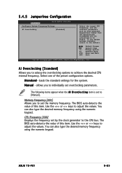
...Displays the frequency set overclocking parameters. The BIOS auto-detects the value of this item. You can also type the desired memory frequency using the numeric keypad. AI Overclocking [Standard] Allows you to set to [Manual]. loads the standard settings for ... bus. allows you to individually set by the clock generator to adjust the values. ASUS T2-PE1 5-25 The following items appear when the A I O v e r c l o c k i n g item is set the memory frequency. 5.4.5 Jumperfree Configuration Advanced BIOS SETUP UTILITY Configure System Frequency/Voltage AI Overclocking [...
...Displays the frequency set overclocking parameters. The BIOS auto-detects the value of this item. You can also type the desired memory frequency using the numeric keypad. AI Overclocking [Standard] Allows you to set to [Manual]. loads the standard settings for ... bus. allows you to individually set by the clock generator to adjust the values. ASUS T2-PE1 5-25 The following items appear when the A I O v e r c l o c k i n g item is set the memory frequency. 5.4.5 Jumperfree Configuration Advanced BIOS SETUP UTILITY Configure System Frequency/Voltage AI Overclocking [...

