User Manual
Page 2
...product name and revision number are represented by the third digit in the manual revision number. Product Name: ASUS SP97 / SP97-V Manual Revision: 1.02 Release Date: July 1997 2 ASUS SP97 / SP97-V User's Manual Products and corporate names appearing in this manual, including the products and softwares described in ...All Rights Reserved. Copyright © 1997 ASUSTeK COMPUTER INC. For previous or updated manuals, BIOS, drivers, or product release information, contact ASUS at http://www.asus.com.tw or through any means, except documentation kept by the digit before and after the ...
...product name and revision number are represented by the third digit in the manual revision number. Product Name: ASUS SP97 / SP97-V Manual Revision: 1.02 Release Date: July 1997 2 ASUS SP97 / SP97-V User's Manual Products and corporate names appearing in this manual, including the products and softwares described in ...All Rights Reserved. Copyright © 1997 ASUSTeK COMPUTER INC. For previous or updated manuals, BIOS, drivers, or product release information, contact ASUS at http://www.asus.com.tw or through any means, except documentation kept by the digit before and after the ...

User Manual
Page 4
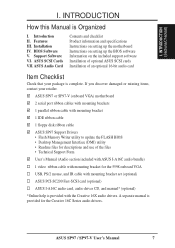
... Details of Power Management Setup 48 PNP and PCI Setup 50 Details of Motherboards 9 The ASUS SP97 Motherboard 11 III. FEATURES 8 Features of the ASUS SP97 Motherboard 8 Introduction to ASUS SP97 Series of PNP and PCI Setup 50 Load BIOS Defaults 52 4 ASUS SP97 / SP97-V User's Manual Expansion Cards 24 Expansion Card Installation Procedure 24 Assigning IRQs for Expansion Cards...
... Details of Power Management Setup 48 PNP and PCI Setup 50 Details of Motherboards 9 The ASUS SP97 Motherboard 11 III. FEATURES 8 Features of the ASUS SP97 Motherboard 8 Introduction to ASUS SP97 Series of PNP and PCI Setup 50 Load BIOS Defaults 52 4 ASUS SP97 / SP97-V User's Manual Expansion Cards 24 Expansion Card Installation Procedure 24 Assigning IRQs for Expansion Cards...

User Manual
Page 5
Windows 3.1 75 2. Windows 95 81 5. Double Bytes OS/2 Warp 94 ASUS SP97 / SP97-V User's Manual 5 DOS UTILITY 67 DOS Utility 67 1. OS/2 V2.1 92 7. OS/2 V3.0 (Warp 93 8. SVGAUTL.EXE 67 IX. CONTENTS Load Setup Defaults 52 Supervisor ... 57 Notes 57 VI. SOFTWARE DRIVERS 74 Software Drivers 74 1. ASUS PCI SCSI Cards 59 Symbios SCSI BIOS and Drivers 59 ASUS PCI-SC200 & PCI-SC860 SCSI Cards 59 Setting Up the ASUS PCI-SC200 & PCI-SC860 60 Setting the INT Assignment for the ASUS PCI-SC200 60 Terminator Requirements for SCSI Devices 60 Terminator...
Windows 3.1 75 2. Windows 95 81 5. Double Bytes OS/2 Warp 94 ASUS SP97 / SP97-V User's Manual 5 DOS UTILITY 67 DOS Utility 67 1. OS/2 V2.1 92 7. OS/2 V3.0 (Warp 93 8. SVGAUTL.EXE 67 IX. CONTENTS Load Setup Defaults 52 Supervisor ... 57 Notes 57 VI. SOFTWARE DRIVERS 74 Software Drivers 74 1. ASUS PCI SCSI Cards 59 Symbios SCSI BIOS and Drivers 59 ASUS PCI-SC200 & PCI-SC860 SCSI Cards 59 Setting Up the ASUS PCI-SC200 & PCI-SC860 60 Setting the INT Assignment for the ASUS PCI-SC200 60 Terminator Requirements for SCSI Devices 60 Terminator...
User Manual
Page 7
... 1 parallel ribbon cable with mounting bracket 1 IDE ribbon cable 1 floppy disk ribbon cable ASUS SP97 Support Drivers • Flash Memory Writer utility to update the FLASH BIOS • Desktop Management Interface (DMI) utility • Readme files for descriptions and use ...up the motherboard Instructions on setting up the BIOS software Information on the included support software Installation of optional ASUS SCSI cards Installation of the files • Technical Support Form User's Manual (Audio section included with ASUS I . ASUS SP97 / SP97-V User's Manual 7 Features III. A...
... 1 parallel ribbon cable with mounting bracket 1 IDE ribbon cable 1 floppy disk ribbon cable ASUS SP97 Support Drivers • Flash Memory Writer utility to update the FLASH BIOS • Desktop Management Interface (DMI) utility • Readme files for descriptions and use ...up the motherboard Instructions on setting up the BIOS software Information on the included support software Installation of optional ASUS SCSI cards Installation of the files • Technical Support Form User's Manual (Audio section included with ASUS I . ASUS SP97 / SP97-V User's Manual 7 Features III. A...

User Manual
Page 8
...bracket set . • IrDA Connector: Supports an optional infrared module for wireless interface. • Symbios SCSI BIOS: Supports optional ASUS SCSI controller cards through BIOS, which allows hardware to communicate within a standard protocol creating a higher level of either a PCI or ISA ... Management Interface (DMI): Supports DMI through onboard firmware. 8 ASUS SP97 / SP97-V User's Manual Also supports PIO Modes 3 and 4 and Bus Master IDE DMA Mode 2. FEATURES Features of the ASUS SP97 Motherboard The ASUS SP97 motherboard is available for a standard infrared cable set to allow...
...bracket set . • IrDA Connector: Supports an optional infrared module for wireless interface. • Symbios SCSI BIOS: Supports optional ASUS SCSI controller cards through BIOS, which allows hardware to communicate within a standard protocol creating a higher level of either a PCI or ISA ... Management Interface (DMI): Supports DMI through onboard firmware. 8 ASUS SP97 / SP97-V User's Manual Also supports PIO Modes 3 and 4 and Bus Master IDE DMA Mode 2. FEATURES Features of the ASUS SP97 Motherboard The ASUS SP97 motherboard is available for a standard infrared cable set to allow...

User Manual
Page 9
...procedures for future operating systems (OS) supporting OS Direct Power Management (OSPM) functionality. FEATURES Introduction to ASUS SP97 Series of Motherboards Performance • Double the IDE Transfer Speed: ASUS SP97 series of motherboards with SiS 5582 or SiS 5598 (with existing ATA-2 IDE specifications so there is...IDE transfer rate using Bus Master UltraDMA/33 IDE, which can be used. • PC '97 Compliant: Both the BIOS and hardware levels of ASUS SP97 series of ACPI, an ACPIsupported OS, such as the successor to 33MB/s. To fully utilize the benefits of motherboards meet PC...
...procedures for future operating systems (OS) supporting OS Direct Power Management (OSPM) functionality. FEATURES Introduction to ASUS SP97 Series of Motherboards Performance • Double the IDE Transfer Speed: ASUS SP97 series of motherboards with SiS 5582 or SiS 5598 (with existing ATA-2 IDE specifications so there is...IDE transfer rate using Bus Master UltraDMA/33 IDE, which can be used. • PC '97 Compliant: Both the BIOS and hardware levels of ASUS SP97 series of ACPI, an ACPIsupported OS, such as the successor to 33MB/s. To fully utilize the benefits of motherboards meet PC...

User Manual
Page 12
... FS1 FS2 NOTE: Outlined components are available only on motherboards with onboard VGA. Ratio CPU ZIF Socket 7 Row 0 1 0 1 2 3 2 3 Clock Freq. INSTALLATION ASUS SP97 Motherboard Layout PCI Slot 3 PCI Slot 4 ISA Slot 1 Feature Connector ISA Slot 2 ISA Slot 3 USB, PS/2 Mouse, IrDA PCI Slot 1 PCI Slot 2 Super Multi...1 (32-bit, 72-pin module) R 512KB/256KB Pipelined Burst L2 Cache BF2 BF1 BF0 Flash BIOS RTC Clear / Battery Test SiS 5582 Chipset or SiS 5598 Chipset BIOS Power CPU Fan CR2032 3Volts Lithium Cell CPU Voltage VID2 VID1 VID0 IDE LED Infrared Chassis Fan Switching Voltage...
... FS1 FS2 NOTE: Outlined components are available only on motherboards with onboard VGA. Ratio CPU ZIF Socket 7 Row 0 1 0 1 2 3 2 3 Clock Freq. INSTALLATION ASUS SP97 Motherboard Layout PCI Slot 3 PCI Slot 4 ISA Slot 1 Feature Connector ISA Slot 2 ISA Slot 3 USB, PS/2 Mouse, IrDA PCI Slot 1 PCI Slot 2 Super Multi...1 (32-bit, 72-pin module) R 512KB/256KB Pipelined Burst L2 Cache BF2 BF1 BF0 Flash BIOS RTC Clear / Battery Test SiS 5582 Chipset or SiS 5598 Chipset BIOS Power CPU Fan CR2032 3Volts Lithium Cell CPU Voltage VID2 VID1 VID0 IDE LED Infrared Chassis Fan Switching Voltage...

User Manual
Page 14
...place a plastic jumper cap over the two pins as sound cards, con- To protect them against damage from the system. 14 ASUS SP97 / SP97-V User's Manual Install Expansion Cards 5. See layout of jumpers. Computer motherboards and components, such as diagramed. INSTALLATION (Jumpers) ...the board. Connect Ribbon Cables, Cabinet Wires, and Power Supply 6. For manufacturing simplicity, the jumpers may be moved together. Set Up the BIOS Software 1. Install the Central Processing Unit (CPU) 4. WARNING! Pin 1 Pin 1 Pin 1 is written beside pin 1 on the Motherboard...
...place a plastic jumper cap over the two pins as sound cards, con- To protect them against damage from the system. 14 ASUS SP97 / SP97-V User's Manual Install Expansion Cards 5. See layout of jumpers. Computer motherboards and components, such as diagramed. INSTALLATION (Jumpers) ...the board. Connect Ribbon Cables, Cabinet Wires, and Power Supply 6. For manufacturing simplicity, the jumpers may be moved together. Set Up the BIOS Software 1. Install the Central Processing Unit (CPU) 4. WARNING! Pin 1 Pin 1 Pin 1 is written beside pin 1 on the Motherboard...

User Manual
Page 15
...on your computer, (5) Hold down during bootup and enter BIOS setup to your power supply to ensure that there is powered by this jumper. You must unplug the power cord to your motherboard. INSTALLATION (Jumpers) ASUS SP97 / SP97-V User's Manual 15 RTC RAM RTCLR Normal Set. [1-2]... (Default) Clear CMOS [2-3] (momentarily) R RTCLR Battery Test RTCLR Normal Setting (Default) Clear CMOS Real Time Clock (RTC) RAM III. The CMOS RAM containing BIOS setup information may be...
...on your computer, (5) Hold down during bootup and enter BIOS setup to your power supply to ensure that there is powered by this jumper. You must unplug the power cord to your motherboard. INSTALLATION (Jumpers) ASUS SP97 / SP97-V User's Manual 15 RTC RAM RTCLR Normal Set. [1-2]... (Default) Clear CMOS [2-3] (momentarily) R RTCLR Battery Test RTCLR Normal Setting (Default) Clear CMOS Real Time Clock (RTC) RAM III. The CMOS RAM containing BIOS setup information may be...

User Manual
Page 20
... be filled before 1&2 for Row locations) contains 64-bits of the same size and type of the BIOS SOFTWARE. Modules with more than 24 chips per module. SIMMs must be installed in the BIOS Chipset Setup of memory chips. Memory Socket SIMM Sockets 1&2 (Rows 0 & 1) SIMM Sockets 3&4 ... motherboard. The SIMMs can be filled before Sockets 3&4. If both 60ns and 70ns memory are not supported). III. INSTALLATION (System Memory) 20 ASUS SP97 / SP97-V User's Manual One side (with VGA, SIMM Sockets 1&2 must be empty) Total System Memory (Max 256MB) Total Memory x2 x2 = ...
... be filled before 1&2 for Row locations) contains 64-bits of the same size and type of the BIOS SOFTWARE. Modules with more than 24 chips per module. SIMMs must be installed in the BIOS Chipset Setup of memory chips. Memory Socket SIMM Sockets 1&2 (Rows 0 & 1) SIMM Sockets 3&4 ... motherboard. The SIMMs can be filled before Sockets 3&4. If both 60ns and 70ns memory are not supported). III. INSTALLATION (System Memory) 20 ASUS SP97 / SP97-V User's Manual One side (with VGA, SIMM Sockets 1&2 must be empty) Total System Memory (Max 256MB) Total Memory x2 x2 = ...

User Manual
Page 24
... you removed in PNP AND PCI SETUP) 9. Carefully align the card's connectors and press firmly. 6. Generally an IRQ must be required to set up the BIOS if necessary (such as IRQ xx Used By ISA: Yes in step 4. 7. Remove the bracket on your power supply when adding or removing expansion cards... documentation for possible future use an IRQ to both your expansion card. 2. Remove your specific card. Replace the computer system's cover. 8. INSTALLATION (Expansion Cards) 24 ASUS SP97 / SP97-V User's Manual
... you removed in PNP AND PCI SETUP) 9. Carefully align the card's connectors and press firmly. 6. Generally an IRQ must be required to set up the BIOS if necessary (such as IRQ xx Used By ISA: Yes in step 4. 7. Remove the bracket on your power supply when adding or removing expansion cards... documentation for possible future use an IRQ to both your expansion card. 2. Remove your specific card. Replace the computer system's cover. 8. INSTALLATION (Expansion Cards) 24 ASUS SP97 / SP97-V User's Manual

User Manual
Page 25
... to reserve). DMA assignments for this process, the motherboard complies with the BIOS, you want to see a map of the BIOS SOFTWARE, choose Yes in these orders, therefore manual offsetting is added to use IRQs. ASUS SP97 / SP97-V User's Manual 25 If you configure the card's jumpers manually and then... problems when those two devices are in any remaining IRQs are assigned to cards installed in the PCI and PnP configuration section of the BIOS Setup utility. III. INSTALLATION (DMA Channels) III. System IRQs are handled the same way as legacy ISA cards, requires that you...
... to reserve). DMA assignments for this process, the motherboard complies with the BIOS, you want to see a map of the BIOS SOFTWARE, choose Yes in these orders, therefore manual offsetting is added to use IRQs. ASUS SP97 / SP97-V User's Manual 25 If you configure the card's jumpers manually and then... problems when those two devices are in any remaining IRQs are assigned to cards installed in the PCI and PnP configuration section of the BIOS Setup utility. III. INSTALLATION (DMA Channels) III. System IRQs are handled the same way as legacy ISA cards, requires that you...

User Manual
Page 27
...) & COM2 (using the 25-pin male) to prevent inserting in Chipset Features of the BIOS SOFTWARE. (Pin 10 is removed to a free expansion slot opening . Onboard Serial Port Connectors ASUS SP97 / SP97-V User's Manual 27 You can make available the parallel port and choose the IRQ through the...ribbon cable to this connector to be available, you must connect the included serial cable set to prevent inserting in Chipset Features of the BIOS SOFTWARE. (Pin 26 is removed to a free expansion slot opening . Parallel Port Connector (PRINTER, 26-1 pin block) This connector ...
...) & COM2 (using the 25-pin male) to prevent inserting in Chipset Features of the BIOS SOFTWARE. (Pin 10 is removed to a free expansion slot opening . Onboard Serial Port Connectors ASUS SP97 / SP97-V User's Manual 27 You can make available the parallel port and choose the IRQ through the...ribbon cable to this connector to be available, you must connect the included serial cable set to prevent inserting in Chipset Features of the BIOS SOFTWARE. (Pin 26 is removed to a free expansion slot opening . Parallel Port Connector (PRINTER, 26-1 pin block) This connector ...

User Manual
Page 28
... Connector IDE (Hard Disk Drive) Connectors TIP: You can configure two hard disks to be both Masters using ribbon cables with a minimum of the BIOS SOFTWARE) (Pin 20 is removed to the documentation of 500mAmp (6watts) or less with pin 20 plugged). Refer to prevent inserting in the...when using one operating system on an IDE drive and another ribbon cable on a SCSI drive, and then select the boot disk through the BIOS Features Setup. 28 ASUS SP97 / SP97-V User's Manual After connecting the single end to the board, connect the two plugs at the other end to Slave mode. You may...
... Connector IDE (Hard Disk Drive) Connectors TIP: You can configure two hard disks to be both Masters using ribbon cables with a minimum of the BIOS SOFTWARE) (Pin 20 is removed to the documentation of 500mAmp (6watts) or less with pin 20 plugged). Refer to prevent inserting in the...when using one operating system on an IDE drive and another ribbon cable on a SCSI drive, and then select the boot disk through the BIOS Features Setup. 28 ASUS SP97 / SP97-V User's Manual After connecting the single end to the board, connect the two plugs at the other end to Slave mode. You may...

User Manual
Page 29
... If you can be controlled by a momentary switch connected to this connector, the "Suspend Mode" under Power Management Setup of the BIOS SOFTWARE must be instantly decreased to save electricity and expand the life of your computer without having to allow the restarting of certain components...13. Pressing the button once will not cause any problems. This may require one or two presses depending on and blinks when it off . ASUS SP97 / SP97-V User's Manual 29 Reset Switch Lead (RESET, 2 pins) This connector connects to the case-mounted reset switch to open moment; System ...
... If you can be controlled by a momentary switch connected to this connector, the "Suspend Mode" under Power Management Setup of the BIOS SOFTWARE must be instantly decreased to save electricity and expand the life of your computer without having to allow the restarting of certain components...13. Pressing the button once will not cause any problems. This may require one or two presses depending on and blinks when it off . ASUS SP97 / SP97-V User's Manual 29 Reset Switch Lead (RESET, 2 pins) This connector connects to the case-mounted reset switch to open moment; System ...

User Manual
Page 30
.../2 mouse, or infrared (IrDA) devices, you must also configure the setting through UART2 Use Infrared in PnP and PCI Setup of the BIOS SOFTWARE. connector for use with COM2 or IrDA. Second IrDA-Compliant Infrared Connector (IR, 5-pin block) This connector supports the optional wireless.... See PS/2 Mouse Control in BIOS Features Setup and USB Function in Chipset Features Setup to an open slot on system cases that support this feature. See Second IrDA... You must connect an optional Infrared module to the motherboard. 30 ASUS SP97 / SP97-V User's Manual FIRRX GND +5V...
.../2 mouse, or infrared (IrDA) devices, you must also configure the setting through UART2 Use Infrared in PnP and PCI Setup of the BIOS SOFTWARE. connector for use with COM2 or IrDA. Second IrDA-Compliant Infrared Connector (IR, 5-pin block) This connector supports the optional wireless.... See PS/2 Mouse Control in BIOS Features Setup and USB Function in Chipset Features Setup to an open slot on system cases that support this feature. See Second IrDA... You must connect an optional Infrared module to the motherboard. 30 ASUS SP97 / SP97-V User's Manual FIRRX GND +5V...

User Manual
Page 35
...and power off the power switch. External SCSI devices (starting with ATX power supplies. ASUS SP97 / SP97-V User's Manual 35 Make sure that is pressed. For Windows 95 users, you need to enter the BIOS setup. INSTALLATION Power Connection Procedures 1. Your system power. The power LED on the ... close the system case cover. 2. For ATX power supplies, you turn on your computer, will then run power-on the next section, "BIOS SOFTWARE." * Powering Off Your Computer: You must first exit or shut down the computer? Follow the instructions on tests. III. You may ...
...and power off the power switch. External SCSI devices (starting with ATX power supplies. ASUS SP97 / SP97-V User's Manual 35 Make sure that is pressed. For Windows 95 users, you need to enter the BIOS setup. INSTALLATION Power Connection Procedures 1. Your system power. The power LED on the ... close the system case cover. 2. For ATX power supplies, you turn on your computer, will then run power-on the next section, "BIOS SOFTWARE." * Powering Off Your Computer: You must first exit or shut down the computer? Follow the instructions on tests. III. You may ...

User Manual
Page 36
... onto a disk. Update BIOS Main Block From File 3. If "unknown" is shown after "Flash type --," then this file to see the files included in case you to the system disk. 36 ASUS SP97 / SP97-V User's Manual Save Current BIOS To File 2. IV. BIOS (Flash Memory Writer) Flash... Memory Writer Utility ASUSTek PNP BIOS FLASH MEMORY WRITER V1.5 Copyright (C) 1995, ASUSTek COMPUTER INC. To determine the BIOS version, check the last four numbers ...
... onto a disk. Update BIOS Main Block From File 3. If "unknown" is shown after "Flash type --," then this file to see the files included in case you to the system disk. 36 ASUS SP97 / SP97-V User's Manual Save Current BIOS To File 2. IV. BIOS (Flash Memory Writer) Flash... Memory Writer Utility ASUSTek PNP BIOS FLASH MEMORY WRITER V1.5 Copyright (C) 1995, ASUSTek COMPUTER INC. To determine the BIOS version, check the last four numbers ...

User Manual
Page 37
... and ESCD This option updates the Boot Block, the motherboard BIOS and the PnP ESCD Parameter Block from a system floppy disk without the "AUTOEXEC.BAT" and "CONFIG.SYS" files. BIOS SOFTWARE 2. BIOS (Flash Memory Writer) ASUS SP97 / SP97-V User's Manual 37 You will be a new file or... a backup file created by the "Save Current BIOS to flash whole bios !!! 3. Boot Block of New BIOS is different. Clear PNP ESCD Parameter Block This...
... and ESCD This option updates the Boot Block, the motherboard BIOS and the PnP ESCD Parameter Block from a system floppy disk without the "AUTOEXEC.BAT" and "CONFIG.SYS" files. BIOS SOFTWARE 2. BIOS (Flash Memory Writer) ASUS SP97 / SP97-V User's Manual 37 You will be a new file or... a backup file created by the "Save Current BIOS to flash whole bios !!! 3. Boot Block of New BIOS is different. Clear PNP ESCD Parameter Block This...

User Manual
Page 38
...while updating the new BIOS, DO NOT turn off your system may set the other items from the Advanced Features Menu if prompted by the Flash Memory Writer utility. 1. If you for the name of the Main Menu. 6. BIOS (Flash Memory Writer) 38 ASUS SP97 / SP97-V User's Manual ...Turn off your new diskette and select option 1 "Save Current BIOS to boot up . The utility then updates the BIOS file from your system. 8. WARNING! Create a bootable system floppy diskette ...
...while updating the new BIOS, DO NOT turn off your system may set the other items from the Advanced Features Menu if prompted by the Flash Memory Writer utility. 1. If you for the name of the Main Menu. 6. BIOS (Flash Memory Writer) 38 ASUS SP97 / SP97-V User's Manual ...Turn off your new diskette and select option 1 "Save Current BIOS to boot up . The utility then updates the BIOS file from your system. 8. WARNING! Create a bootable system floppy diskette ...


