User Manual
Page 2
... Technology Ltd. • Adobe and Acrobat are registered trademarks of Adobe Systems Incorporated. Product Name: ASUS SP97 / SP97-V Manual Revision: 1.02 Release Date: July 1997 2 ASUS SP97 / SP97-V User's Manual All Rights Reserved. Products and corporate names appearing in this manual, including the products...only for backup purposes, without intent to the owners' benefit, without the express written permission of ASUSTeK COMPUTER INC. ("ASUS"). ASUS PROVIDES THIS MANUAL "AS IS" WITHOUT WARRANTY OF ANY KIND, EITHER EXPRESS OR IMPLIED, INCLUDING BUT NOT LIMITED TO ...
... Technology Ltd. • Adobe and Acrobat are registered trademarks of Adobe Systems Incorporated. Product Name: ASUS SP97 / SP97-V Manual Revision: 1.02 Release Date: July 1997 2 ASUS SP97 / SP97-V User's Manual All Rights Reserved. Products and corporate names appearing in this manual, including the products...only for backup purposes, without intent to the owners' benefit, without the express written permission of ASUSTeK COMPUTER INC. ("ASUS"). ASUS PROVIDES THIS MANUAL "AS IS" WITHOUT WARRANTY OF ANY KIND, EITHER EXPRESS OR IMPLIED, INCLUDING BUT NOT LIMITED TO ...

User Manual
Page 3
...tw Technical Support Fax: +886-2-895-9254 BBS: +886-2-896-4667 Email: tsd@asus.com.tw WWW: www.asus.com.tw Gopher: gopher.asus.com.tw FTP: ftp.asus.com.tw/pub/ASUS ASUS COMPUTER INTERNATIONAL Marketing Info Address: 721 Charcot Avenue, San Jose, CA 95131, USA ...asus.com.tw WWW: www.asus.com ASUS COMPUTER GmbH Marketing Info Address: Harkort Str. 25, 40880 Ratingen, BRD, Germany Telephone: 49-2102-445011 Fax: 49-2102-442066 Email: info-ger@asus.com.tw Technical Support BBS: 49-2102-448690 Email: tsd-ger@asus.com.tw Hotline: 49-2102-499712 ASUS SP97 / SP97...
...tw Technical Support Fax: +886-2-895-9254 BBS: +886-2-896-4667 Email: tsd@asus.com.tw WWW: www.asus.com.tw Gopher: gopher.asus.com.tw FTP: ftp.asus.com.tw/pub/ASUS ASUS COMPUTER INTERNATIONAL Marketing Info Address: 721 Charcot Avenue, San Jose, CA 95131, USA ...asus.com.tw WWW: www.asus.com ASUS COMPUTER GmbH Marketing Info Address: Harkort Str. 25, 40880 Ratingen, BRD, Germany Telephone: 49-2102-445011 Fax: 49-2102-442066 Email: info-ger@asus.com.tw Technical Support BBS: 49-2102-448690 Email: tsd-ger@asus.com.tw Hotline: 49-2102-499712 ASUS SP97 / SP97...

User Manual
Page 4
FEATURES 8 Features of the ASUS SP97 Motherboard 8 Introduction to ASUS SP97 Series of PNP and PCI Setup 50 Load BIOS Defaults 52 4 ASUS SP97 / SP97-V User's Manual INSTALLATION 12 ASUS SP97 Motherboard Layout 12 Installation Steps 14 1. System Memory (SIMM 20 SIMM Installation 21 3. Expansion Cards 24 Expansion Card Installation Procedure 24 Assigning IRQs for Expansion ... Details of Chipset Features Setup 45 Power Management Setup 48 Details of Power Management Setup 48 PNP and PCI Setup 50 Details of Motherboards 9 The ASUS SP97 Motherboard 11 III.
FEATURES 8 Features of the ASUS SP97 Motherboard 8 Introduction to ASUS SP97 Series of PNP and PCI Setup 50 Load BIOS Defaults 52 4 ASUS SP97 / SP97-V User's Manual INSTALLATION 12 ASUS SP97 Motherboard Layout 12 Installation Steps 14 1. System Memory (SIMM 20 SIMM Installation 21 3. Expansion Cards 24 Expansion Card Installation Procedure 24 Assigning IRQs for Expansion ... Details of Chipset Features Setup 45 Power Management Setup 48 Details of Power Management Setup 48 PNP and PCI Setup 50 Details of Motherboards 9 The ASUS SP97 Motherboard 11 III.

User Manual
Page 5
... 74 Software Drivers 74 1. Autodesk ADI 4.2 -Protected Mode 86 6. Double Bytes OS/2 Warp 94 ASUS SP97 / SP97-V User's Manual 5 DOS UTILITY 67 DOS Utility 67 1. Windows 3.1 75 2. OS/2 V3.0 (Warp 93 8. OS/2 V2.1 92 7. ASUS I-A16C Audio Card 63 ASUS I-A16C Audio Features 63 Unpacking and Handling Precautions 63 Layout and Connectors 64 Connectors 64...
... 74 Software Drivers 74 1. Autodesk ADI 4.2 -Protected Mode 86 6. Double Bytes OS/2 Warp 94 ASUS SP97 / SP97-V User's Manual 5 DOS UTILITY 67 DOS Utility 67 1. Windows 3.1 75 2. OS/2 V3.0 (Warp 93 8. OS/2 V2.1 92 7. ASUS I-A16C Audio Card 63 ASUS I-A16C Audio Features 63 Unpacking and Handling Precautions 63 Layout and Connectors 64 Connectors 64...

User Manual
Page 6
... and, if not installed and used in accordance with FCC regulations. This equipment generates, uses and can be determined by one or more of Communications. 6 ASUS SP97 / SP97-V User's Manual If this equipment. WARNING! Changes or modifications to this unit not expressly approved by the party responsible for connection of the monitor to...
... and, if not installed and used in accordance with FCC regulations. This equipment generates, uses and can be determined by one or more of Communications. 6 ASUS SP97 / SP97-V User's Manual If this equipment. WARNING! Changes or modifications to this unit not expressly approved by the party responsible for connection of the monitor to...
User Manual
Page 7
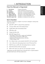
...the included support software Installation of optional ASUS SCSI cards Installation of the files • Technical Support Form User's Manual (Audio section included with ASUS I . ASUS SP97 / SP97-V User's Manual 7 INTRODUCTION How this Manual is Organized I . Features III. ASUS SCSI Cards VII. A separate manual...port ribbon cables with mounting brackets 1 parallel ribbon cable with mounting bracket 1 IDE ribbon cable 1 floppy disk ribbon cable ASUS SP97 Support Drivers • Flash Memory Writer utility to update the FLASH BIOS • Desktop Management Interface (DMI) utility &#...
...the included support software Installation of optional ASUS SCSI cards Installation of the files • Technical Support Form User's Manual (Audio section included with ASUS I . ASUS SP97 / SP97-V User's Manual 7 INTRODUCTION How this Manual is Organized I . Features III. ASUS SCSI Cards VII. A separate manual...port ribbon cables with mounting brackets 1 parallel ribbon cable with mounting bracket 1 IDE ribbon cable 1 floppy disk ribbon cable ASUS SP97 Support Drivers • Flash Memory Writer utility to update the FLASH BIOS • Desktop Management Interface (DMI) utility &#...

User Manual
Page 8
...keyboard controller. BIOS supports IDE CDROM or SCSI device bootup. • Level 2 Cache: Comes with soft-on the system chassis. FEATURES (ASUS SP97) II. Supports four IDE devices more than 8.4GB in video controller and supports video shared memory from 1MB to 4MB. • Versatile ...32-bit PCI slots, and one PCI/ISA shared slot for wireless interface. • Symbios SCSI BIOS: Supports optional ASUS SCSI controller cards through onboard firmware. 8 ASUS SP97 / SP97-V User's Manual The SiS5598 chipset has a built-in two channels up to 256MB. • Easy Installation: Incorporates ...
...keyboard controller. BIOS supports IDE CDROM or SCSI device bootup. • Level 2 Cache: Comes with soft-on the system chassis. FEATURES (ASUS SP97) II. Supports four IDE devices more than 8.4GB in video controller and supports video shared memory from 1MB to 4MB. • Versatile ...32-bit PCI slots, and one PCI/ISA shared slot for wireless interface. • Symbios SCSI BIOS: Supports optional ASUS SCSI controller cards through onboard firmware. 8 ASUS SP97 / SP97-V User's Manual The SiS5598 chipset has a built-in two channels up to 256MB. • Easy Installation: Incorporates ...

User Manual
Page 9
... Windows NT. To fully utilize the benefits of ACPI, an ACPIsupported OS, such as the successor to ASUS SP97 Series of Motherboards Performance • Double the IDE Transfer Speed: ASUS SP97 series of motherboards with SiS 5582 or SiS 5598 (with VGA) series of motherboards meet PC '97 compliancy... (OSPM) functionality. FEATURES Introduction to Windows 95, must be ready around-the-clock, yet satisfy all the energy saving standards. FEATURES (SP97 Series) II. II. This new technology is compatible with existing ATA-2 IDE specifications so there is no need to upgrade current hard disk...
... Windows NT. To fully utilize the benefits of ACPI, an ACPIsupported OS, such as the successor to ASUS SP97 Series of Motherboards Performance • Double the IDE Transfer Speed: ASUS SP97 series of motherboards with SiS 5582 or SiS 5598 (with VGA) series of motherboards meet PC '97 compliancy... (OSPM) functionality. FEATURES Introduction to Windows 95, must be ready around-the-clock, yet satisfy all the energy saving standards. FEATURES (SP97 Series) II. II. This new technology is compatible with existing ATA-2 IDE specifications so there is no need to upgrade current hard disk...

User Manual
Page 10
(This page was intentionally left blank) 10 ASUS SP97 / SP97-V User's Manual
(This page was intentionally left blank) 10 ASUS SP97 / SP97-V User's Manual

User Manual
Page 11
FEATURES (ASUS SP97) II. ATX Power Conn. Floppy Connector IDE Connectors USB, PS/2 Mouse, Infrared Super Multi I/O Parallel Serial Keyboard 4 SIMM Sockets SiS5582 or 5598 (VGA) Chipset Programmable Flash ROM CPU ZIF Socket 7 Switching Voltage Regulators 512KB/256KB Pipelined Burst L2 Cache ASUS SP97 / SP97-V User's Manual 11 FEATURES The ASUS SP97 Motherboard 3 PCI Slots 2 ISA Slots 1 ISA/PCI Shared Slot AT Power Conn. II.
FEATURES (ASUS SP97) II. ATX Power Conn. Floppy Connector IDE Connectors USB, PS/2 Mouse, Infrared Super Multi I/O Parallel Serial Keyboard 4 SIMM Sockets SiS5582 or 5598 (VGA) Chipset Programmable Flash ROM CPU ZIF Socket 7 Switching Voltage Regulators 512KB/256KB Pipelined Burst L2 Cache ASUS SP97 / SP97-V User's Manual 11 FEATURES The ASUS SP97 Motherboard 3 PCI Slots 2 ISA Slots 1 ISA/PCI Shared Slot AT Power Conn. II.

User Manual
Page 12
FS3 Clock Freq FS0 FS1 FS2 NOTE: Outlined components are available only on motherboards with onboard VGA. III. INSTALLATION ASUS SP97 Motherboard Layout PCI Slot 3 PCI Slot 4 ISA Slot 1 Feature Connector ISA Slot 2 ISA Slot 3 USB, PS/2 Mouse, IrDA PCI Slot 1 PCI Slot 2 Super Multi-I/O VGA ...BIOS Power CPU Fan CR2032 3Volts Lithium Cell CPU Voltage VID2 VID1 VID0 IDE LED Infrared Chassis Fan Switching Voltage Regulators Freq. Panel Connectors 12 ASUS SP97 / SP97-V User's Manual Ratio CPU ZIF Socket 7 Row 0 1 0 1 2 3 2 3 Clock Freq. INSTALLATION (Motherboard Layout) III.
FS3 Clock Freq FS0 FS1 FS2 NOTE: Outlined components are available only on motherboards with onboard VGA. III. INSTALLATION ASUS SP97 Motherboard Layout PCI Slot 3 PCI Slot 4 ISA Slot 1 Feature Connector ISA Slot 2 ISA Slot 3 USB, PS/2 Mouse, IrDA PCI Slot 1 PCI Slot 2 Super Multi-I/O VGA ...BIOS Power CPU Fan CR2032 3Volts Lithium Cell CPU Voltage VID2 VID1 VID0 IDE LED Infrared Chassis Fan Switching Voltage Regulators Freq. Panel Connectors 12 ASUS SP97 / SP97-V User's Manual Ratio CPU ZIF Socket 7 Row 0 1 0 1 2 3 2 3 Clock Freq. INSTALLATION (Motherboard Layout) III.

User Manual
Page 13
...) 18) IDELED p. 32 IDE Activity LED (2 pins) 19) VGACON (optional) p. 32 VGA Connector (16-pin block) 20) FEATURE p. 33 Video Feature Connector (28-pin block) ASUS SP97 / SP97-V User's Manual 13 III.
...) 18) IDELED p. 32 IDE Activity LED (2 pins) 19) VGACON (optional) p. 32 VGA Connector (16-pin block) 20) FEATURE p. 33 Video Feature Connector (28-pin block) ASUS SP97 / SP97-V User's Manual 13 III.

User Manual
Page 14
... shown graphically as to connect pins 1 & 2 and to touch the IC chips, leads, or circuitry. 4. Settings with the keyboard connector away from the system. 14 ASUS SP97 / SP97-V User's Manual Hold components by the edges and try not to connect pins 2 & 3. Set Up the BIOS Software 1. Pin 1 Pin 1 Pin 1 is written beside pin...
... shown graphically as to connect pins 1 & 2 and to touch the IC chips, leads, or circuitry. 4. Settings with the keyboard connector away from the system. 14 ASUS SP97 / SP97-V User's Manual Hold components by the edges and try not to connect pins 2 & 3. Set Up the BIOS Software 1. Pin 1 Pin 1 Pin 1 is written beside pin...

User Manual
Page 15
... Defaults" and reenter any user information after removing and reapplying this jumper. You must enter BIOS to Normal Set., (4) Turn on your motherboard. INSTALLATION (Jumpers) ASUS SP97 / SP97-V User's Manual 15 III. Battery Test Jumper (BAT_TEST) You can test the battery's current by this jumper and attaching a current meter to ensure that there...
... Defaults" and reenter any user information after removing and reapplying this jumper. You must enter BIOS to Normal Set., (4) Turn on your motherboard. INSTALLATION (Jumpers) ASUS SP97 / SP97-V User's Manual 15 III. Battery Test Jumper (BAT_TEST) You can test the battery's current by this jumper and attaching a current meter to ensure that there...

User Manual
Page 16
.../MX (2.8Volts) P54C/CS/K5 (3.4V) (STD) K6-166/200 (2.9Volts) CPU Vcore Voltage ID Selection 1 2 3 K6-233 (3.2Volts) 1 2 3 P54C/CS/6x86 (3.5V) (VRE) 16 ASUS SP97 / SP97-V User's Manual
.../MX (2.8Volts) P54C/CS/K5 (3.4V) (STD) K6-166/200 (2.9Volts) CPU Vcore Voltage ID Selection 1 2 3 K6-233 (3.2Volts) 1 2 3 P54C/CS/6x86 (3.5V) (VRE) 16 ASUS SP97 / SP97-V User's Manual

User Manual
Page 17
... External Clock (BUS) Frequency Selection III. The BUS Clock multiplied by the BUS Ratio equals the CPU's internal frequency (the advertised CPU speed). INSTALLATION (Jumpers) ASUS SP97 / SP97-V User's Manual 17 CPU External Frequency (BUS) Selection (FS0, FS1, FS2, FS3) These jumpers tell the clock generator what frequency to send to BUS Frequency...
... External Clock (BUS) Frequency Selection III. The BUS Clock multiplied by the BUS Ratio equals the CPU's internal frequency (the advertised CPU speed). INSTALLATION (Jumpers) ASUS SP97 / SP97-V User's Manual 17 CPU External Frequency (BUS) Selection (FS0, FS1, FS2, FS3) These jumpers tell the clock generator what frequency to send to BUS Frequency...

User Manual
Page 18
... Pentium Intel Pentium Intel Pentium Intel Pentium (BUS Freq.) Freq. Bootup screen will show 6x86-P166+ with the Cyrix PR166+ installed on this motherboard. 18 ASUS SP97 / SP97-V User's Manual FS0 FS1 FS2 FS3 233MHz 3.5x 66MHz [2-3] [1-2] [2-3] [1-2] 200MHz 3.0x 66MHz [2-3] [1-2] [2-3] [1-2] 166MHz 2.5x 66MHz [2-3] [1-2] [2-3] [1-2] 150MHz 2.5x 60MHz [1-2] [2-3] [2-3] [1-2] 133MHz 2.0x 66MHz [2-3] [1-2] [2-3] [1-2] 120MHz 2.0x 60MHz [1-2] [2-3] [2-3] [1-2] 100MHz...
... Pentium Intel Pentium Intel Pentium Intel Pentium (BUS Freq.) Freq. Bootup screen will show 6x86-P166+ with the Cyrix PR166+ installed on this motherboard. 18 ASUS SP97 / SP97-V User's Manual FS0 FS1 FS2 FS3 233MHz 3.5x 66MHz [2-3] [1-2] [2-3] [1-2] 200MHz 3.0x 66MHz [2-3] [1-2] [2-3] [1-2] 166MHz 2.5x 66MHz [2-3] [1-2] [2-3] [1-2] 150MHz 2.5x 60MHz [1-2] [2-3] [2-3] [1-2] 133MHz 2.0x 66MHz [2-3] [1-2] [2-3] [1-2] 120MHz 2.0x 60MHz [1-2] [2-3] [2-3] [1-2] 100MHz...

User Manual
Page 19
... you to turn the onboard VGA on VGA expansion card. You need to disable the onboard VGA to set the VGA interrupt method. INSTALLATION (Jumpers) ASUS SP97 / SP97-V User's Manual 19 VGA_SEL VGA_INT VGA_SEL1 VGA_SEL VGA_INT VGA_SEL1 R Interrupt Disabled (Default) Interrupt by the onboard chipset. VGA Selection (VGA_SEL & VGA_SEL1) (with onboard VGA version...
... you to turn the onboard VGA on VGA expansion card. You need to disable the onboard VGA to set the VGA interrupt method. INSTALLATION (Jumpers) ASUS SP97 / SP97-V User's Manual 19 VGA_SEL VGA_INT VGA_SEL1 VGA_SEL VGA_INT VGA_SEL1 R Interrupt Disabled (Default) Interrupt by the onboard chipset. VGA Selection (VGA_SEL & VGA_SEL1) (with onboard VGA version...

User Manual
Page 20
... must be empty) 4MB, 8MB, 16MB, 32MB, 64MB 72-pin FPM or EDO SIMM (DIMM Sockets must be filled before Sockets 3&4. INSTALLATION (System Memory) 20 ASUS SP97 / SP97-V User's Manual System Memory (SIMM) This motherboard supports four 72-pin, 32-bit SIMMs (Single Inline Memory Modules) of the memory subsystem and will be...
... must be empty) 4MB, 8MB, 16MB, 32MB, 64MB 72-pin FPM or EDO SIMM (DIMM Sockets must be filled before Sockets 3&4. INSTALLATION (System Memory) 20 ASUS SP97 / SP97-V User's Manual System Memory (SIMM) This motherboard supports four 72-pin, 32-bit SIMMs (Single Inline Memory Modules) of the memory subsystem and will be...

User Manual
Page 21
... in only one orientation as shown because the plastic safety tab on one end of the SIMM sockets requires the notched end of the clips ASUS SP97 / SP97-V User's Manual 21 Press the memory module firmly into place starting from a 45-degree angle, making sure that it clicks into a vertical position so that...
... in only one orientation as shown because the plastic safety tab on one end of the SIMM sockets requires the notched end of the clips ASUS SP97 / SP97-V User's Manual 21 Press the memory module firmly into place starting from a 45-degree angle, making sure that it clicks into a vertical position so that...


