

User Guide
Page 13
... with different models. Package contents Check your motherboard package for the following items User Manual ASUS SABERTOOTH Z97 MARK S motherboard Technical documentations, certification, and warranty card Support DVD 4 x Serial ATA 6.0 Gb/s cables 1 x ASUS SLI™ bridge connector (7 cm) 1 x ASUS Q-Shield 1 x 2-in-1 ASUS Q-Connector kit 1 x 35 mm Assistant fan 1 x 40 mm Assistant fan 2 x short fan screws 4 x long fan...
... with different models. Package contents Check your motherboard package for the following items User Manual ASUS SABERTOOTH Z97 MARK S motherboard Technical documentations, certification, and warranty card Support DVD 4 x Serial ATA 6.0 Gb/s cables 1 x ASUS SLI™ bridge connector (7 cm) 1 x ASUS Q-Shield 1 x 2-in-1 ASUS Q-Connector kit 1 x 35 mm Assistant fan 1 x 40 mm Assistant fan 2 x short fan screws 4 x long fan...

User Guide
Page 15
Intel® Z97 Express Chipset Intel® Z97 Express Chipset is the PCI Express bus standard that supports the LGA1150 socket for the 4th, New 4th, and 5th generation Intel® Core™ ...; and Celeron® processors. Quad-GPU SLI and Quad GPU CrossFireX™ Support This motherboard features the most powerful Intel® Z97 platform that features data transfer rates of PCIe 2.0. Chapter 1 ASUS SABERTOOTH Z97 MARK S 1-1 PCI Express® 3.0 PCI Express® 3.0 (PCIe 3.0) is a single chipset that provides twice the performance and speed of DDR3 1866...
Intel® Z97 Express Chipset Intel® Z97 Express Chipset is the PCI Express bus standard that supports the LGA1150 socket for the 4th, New 4th, and 5th generation Intel® Core™ ...; and Celeron® processors. Quad-GPU SLI and Quad GPU CrossFireX™ Support This motherboard features the most powerful Intel® Z97 platform that features data transfer rates of PCIe 2.0. Chapter 1 ASUS SABERTOOTH Z97 MARK S 1-1 PCI Express® 3.0 PCI Express® 3.0 (PCIe 3.0) is a single chipset that provides twice the performance and speed of DDR3 1866...

User Guide
Page 17
... the motherboard easier to support the Thermal Armor, CPU, VGA card, additional expansion cards, and other peripherals. The ASUS exclusive AntiStatic chip and circuit design, and the I /O filter and special shields that help reduce dust build-up ...military-standard) The motherboard's TUF components features military-standard robust TUF new chokes, titanium solid state capacitors, and MOSFETS. Chapter 1 ASUS SABERTOOTH Z97 MARK S 1-3 These controllers offers ultra-precise memory and voltage tuning for optimal system efficiency, stability and performance. Dust Defenders** Dust Defenders...
... the motherboard easier to support the Thermal Armor, CPU, VGA card, additional expansion cards, and other peripherals. The ASUS exclusive AntiStatic chip and circuit design, and the I /O filter and special shields that help reduce dust build-up ...military-standard) The motherboard's TUF components features military-standard robust TUF new chokes, titanium solid state capacitors, and MOSFETS. Chapter 1 ASUS SABERTOOTH Z97 MARK S 1-3 These controllers offers ultra-precise memory and voltage tuning for optimal system efficiency, stability and performance. Dust Defenders** Dust Defenders...

User Guide
Page 19
... compatible USB 3.0 peripherals without entering the existing BIOS or operating system. Chapter 1 ASUS SABERTOOTH Z97 MARK S 1-5 1.1.6 ASUS Exclusive Features Remote GO! With ASUS Remote GO!, you to -use and enjoy these ASUS Remote GO! Conveniently use software package. USB Charger+ With a dedicated onboard controller,...This all up to use functions, with no need for UEFI BIOS updates, and download the latest BIOS automatically. USB 3.0 Boost ASUS USB 3.0 Boost, which supports USB 3.0 standard UASP (USB Attached SCSI Protocol), significantly increases a USB device's transfer speed up...
... compatible USB 3.0 peripherals without entering the existing BIOS or operating system. Chapter 1 ASUS SABERTOOTH Z97 MARK S 1-5 1.1.6 ASUS Exclusive Features Remote GO! With ASUS Remote GO!, you to -use and enjoy these ASUS Remote GO! Conveniently use software package. USB Charger+ With a dedicated onboard controller,...This all up to use functions, with no need for UEFI BIOS updates, and download the latest BIOS automatically. USB 3.0 Boost ASUS USB 3.0 Boost, which supports USB 3.0 standard UASP (USB Attached SCSI Protocol), significantly increases a USB device's transfer speed up...

User Guide
Page 21
... the power supply case, to avoid damaging them due to static electricity. • Hold components by the edges to the motherboard, peripherals, or components. Chapter 1 ASUS SABERTOOTH Z97 MARK S 1-7 Failure to do so may cause severe damage to avoid touching the ICs on them. • Whenever you uninstall any component, place it on a grounded...
... the power supply case, to avoid damaging them due to static electricity. • Hold components by the edges to the motherboard, peripherals, or components. Chapter 1 ASUS SABERTOOTH Z97 MARK S 1-7 Failure to do so may cause severe damage to avoid touching the ICs on them. • Whenever you uninstall any component, place it on a grounded...

User Guide
Page 23
...]; TPM connector (20-1 pin TPM) Page 1-37 1-35 1-10 1-11 1-27 1-32 1-31 1-29 1-28 1-39 1-38 1-32 1-34 1-40 1-36 1-36 1-33 1-39 Chapter 1 ASUS SABERTOOTH Z97 MARK S 1-9 DDR3 DIMM slots 5. Clear RTC RAM (3-pin CLRTC) 10. DirectKey connector (2-pin DRCT) 11. Front panel audio connector (10-1 pin AAFP) 17. Layout contents Connectors...
...]; TPM connector (20-1 pin TPM) Page 1-37 1-35 1-10 1-11 1-27 1-32 1-31 1-29 1-28 1-39 1-38 1-32 1-34 1-40 1-36 1-36 1-33 1-39 Chapter 1 ASUS SABERTOOTH Z97 MARK S 1-9 DDR3 DIMM slots 5. Clear RTC RAM (3-pin CLRTC) 10. DirectKey connector (2-pin DRCT) 11. Front panel audio connector (10-1 pin AAFP) 17. Layout contents Connectors...

User Guide
Page 25
DO NOT install a DDR or DDR2 memory module to the DDR3 slot. A DDR3 module is notched differently from a DDR or DDR2 module. Recommended memory configurations Chapter 1 ASUS SABERTOOTH Z97 MARK S 1-11 1.2.4 System memory The motherboard comes with four Double Data Rate 3 (DDR3) Dual Inline Memory Modules (DIMM) slots.
DO NOT install a DDR or DDR2 memory module to the DDR3 slot. A DDR3 module is notched differently from a DDR or DDR2 module. Recommended memory configurations Chapter 1 ASUS SABERTOOTH Z97 MARK S 1-11 1.2.4 System memory The motherboard comes with four Double Data Rate 3 (DDR3) Dual Inline Memory Modules (DIMM) slots.

User Guide
Page 27
... Voltage 1.65V 1.65V 1.65V 1.65V DIMM socket support (Optional) 2 4 • • • • • • • Chapter 1 ASUS SABERTOOTH Z97 MARK S 1-13 Size SS/ Chip Chip DS Brand NO. Size SS/ Chip Chip DS Brand NO. SABERTOOTH Z97 MARK S Motherboard Qualified Vendors Lists (QVL) DDR3 3200 MHz capability Vendors Part No. Size SS/ Chip Chip DS Brand...
... Voltage 1.65V 1.65V 1.65V 1.65V DIMM socket support (Optional) 2 4 • • • • • • • Chapter 1 ASUS SABERTOOTH Z97 MARK S 1-13 Size SS/ Chip Chip DS Brand NO. Size SS/ Chip Chip DS Brand NO. SABERTOOTH Z97 MARK S Motherboard Qualified Vendors Lists (QVL) DDR3 3200 MHz capability Vendors Part No. Size SS/ Chip Chip DS Brand...

User Guide
Page 29
...-11-11-30 1.65 • •• 16GB (4x 4GB) DS - - 11-11-11-30 1.65 • •• (continued on the next page) Chapter 1 ASUS SABERTOOTH Z97 MARK S 1-15 Size SS/ DS 78.BAGFF.AFC0C(XMP) 8GB ( 2x 4GB ) DS 78.BAGFR.AFD0C(XMP) 8GB ( 2x 4GB ) DS 78.CAGFF.AFD0C(XMP) 16GB...(XMP) GOC316GB2400C11QC(XMP) Size 8GB (2x 4GB) 16GB (2x 8GB) 8GB (2x 4GB) 8GB (2x 4GB) 16GB (2x 8GB) SS/ Chip Chip DS Brand NO. SABERTOOTH Z97 MARK S Motherboard Qualified Vendors Lists (QVL) DDR3 2666 MHz capability Vendors Apacer Apacer Apacer CORSAIR G.SKILL GEIL KINGSTON Part No.
...-11-11-30 1.65 • •• 16GB (4x 4GB) DS - - 11-11-11-30 1.65 • •• (continued on the next page) Chapter 1 ASUS SABERTOOTH Z97 MARK S 1-15 Size SS/ DS 78.BAGFF.AFC0C(XMP) 8GB ( 2x 4GB ) DS 78.BAGFR.AFD0C(XMP) 8GB ( 2x 4GB ) DS 78.CAGFF.AFD0C(XMP) 16GB...(XMP) GOC316GB2400C11QC(XMP) Size 8GB (2x 4GB) 16GB (2x 8GB) 8GB (2x 4GB) 8GB (2x 4GB) 16GB (2x 8GB) SS/ Chip Chip DS Brand NO. SABERTOOTH Z97 MARK S Motherboard Qualified Vendors Lists (QVL) DDR3 2666 MHz capability Vendors Apacer Apacer Apacer CORSAIR G.SKILL GEIL KINGSTON Part No.

User Guide
Page 31
...; •• 1.5 • •• 1.5 • •• 1.5 • •• 1.5 •• 1.5 •• 1.5 • •• 1.5 • •• 1.5 • •• Chapter 1 ASUS SABERTOOTH Z97 MARK S 1-17 Timing Voltage DIMM socket support (Optional) 1 24 SS - - 2133-11-12-11-30 - • •• 8GB DS - - 2133-11-12-11-30 - •...
...; •• 1.5 • •• 1.5 • •• 1.5 • •• 1.5 •• 1.5 •• 1.5 • •• 1.5 • •• 1.5 • •• Chapter 1 ASUS SABERTOOTH Z97 MARK S 1-17 Timing Voltage DIMM socket support (Optional) 1 24 SS - - 2133-11-12-11-30 - • •• 8GB DS - - 2133-11-12-11-30 - •...

User Guide
Page 33
...; •• •• • •• • •• • •• • •• • •• (continued on the next page) Chapter 1 ASUS SABERTOOTH Z97 MARK S 1-19 A-DATA AD3U1600W4G11 Size SS/ Chip DS Brand Chip NO. 4GB SS A-DATA 3WCD-1211A Timing 11-11-11-28 Voltage - DDR3 1600 MHz capability...
...; •• •• • •• • •• • •• • •• • •• (continued on the next page) Chapter 1 ASUS SABERTOOTH Z97 MARK S 1-19 A-DATA AD3U1600W4G11 Size SS/ Chip DS Brand Chip NO. 4GB SS A-DATA 3WCD-1211A Timing 11-11-11-28 Voltage - DDR3 1600 MHz capability...

User Guide
Page 39
Chapter 1 Slot No. 1 2 3 4 5 6 Slot Description PCIe 2.0 x1_1 slot PCIe 3.0/2.0 x16_1 slot PCIe 2.0 x1_2 slot PCIe 3.0/2.0 x16_2 slot PCIe 2.0 x1_3 slot PCIe 2.0 x16_3 slot ASUS SABERTOOTH Z97 MARK S 1-25 1.2.5 Expansion slots Unplug the power cord before adding or removing expansion cards. Failure to do so may cause you physical injury and damage motherboard components.
Chapter 1 Slot No. 1 2 3 4 5 6 Slot Description PCIe 2.0 x1_1 slot PCIe 3.0/2.0 x16_1 slot PCIe 2.0 x1_2 slot PCIe 3.0/2.0 x16_2 slot PCIe 2.0 x1_3 slot PCIe 2.0 x16_3 slot ASUS SABERTOOTH Z97 MARK S 1-25 1.2.5 Expansion slots Unplug the power cord before adding or removing expansion cards. Failure to do so may cause you physical injury and damage motherboard components.

User Guide
Page 41
... manual or on a bare or opencase system. function. button Installing DIMMs that you download and update to the latest BIOS version from the ASUS website at www.asus.com. • If you turn off the computer and unplug the power cord for about 30 seconds for the system to test one set... off the system and reinstall the DIMM before using the MemOK! If the installed DIMMs still fail to boot and load the BIOS default settings. ASUS SABERTOOTH Z97 MARK S 1-27 Chapter 1 Replace the DIMMs with the motherboard may cause system boot failure, and the DRAM_LED near the MemOK!
... manual or on a bare or opencase system. function. button Installing DIMMs that you download and update to the latest BIOS version from the ASUS website at www.asus.com. • If you turn off the computer and unplug the power cord for about 30 seconds for the system to test one set... off the system and reinstall the DIMM before using the MemOK! If the installed DIMMs still fail to boot and load the BIOS default settings. ASUS SABERTOOTH Z97 MARK S 1-27 Chapter 1 Replace the DIMMs with the motherboard may cause system boot failure, and the DRAM_LED near the MemOK!

User Guide
Page 43
Chapter 1 ASUS SABERTOOTH Z97 MARK S 1-29 To go back to its default CPU voltage setting, insert the jumper to set a higher CPU voltage for a flexible overclocking system, depending on the type of the installed CPU. CPU Over Voltage jumper (3-pin CPU_OV) The CPU Over Voltage jumper allows you to pins 1-2. To gain more CPU voltage setting, insert the jumper to pins 2-3. 2.
Chapter 1 ASUS SABERTOOTH Z97 MARK S 1-29 To go back to its default CPU voltage setting, insert the jumper to set a higher CPU voltage for a flexible overclocking system, depending on the type of the installed CPU. CPU Over Voltage jumper (3-pin CPU_OV) The CPU Over Voltage jumper allows you to pins 1-2. To gain more CPU voltage setting, insert the jumper to pins 2-3. 2.

User Guide
Page 45
... cables. Intel® Z97 Serial ATA 6.0 Gb/s connectors (7-pin SATA6G_1-2 [black]; SATA6G_3-4 [black] SATA Express [black at the bottom]) These connectors connect to [AHCI Mode] by default. If you can create a RAID 0, 1, 5, and 10 configuration with the Intel® Rapid Storage Technology through the onboard Intel® Z97 chipset. ASUS SABERTOOTH Z97 MARK S 1-31 1.2.9 Internal connectors...
... cables. Intel® Z97 Serial ATA 6.0 Gb/s connectors (7-pin SATA6G_1-2 [black]; SATA6G_3-4 [black] SATA Express [black at the bottom]) These connectors connect to [AHCI Mode] by default. If you can create a RAID 0, 1, 5, and 10 configuration with the Intel® Rapid Storage Technology through the onboard Intel® Z97 chipset. ASUS SABERTOOTH Z97 MARK S 1-31 1.2.9 Internal connectors...

User Guide
Page 47
Connect the S/PDIF Out module cable to this connector, then install the module to a slot opening at the back of the system chassis. Chapter 1 ASUS SABERTOOTH Z97 MARK S 1-33 The S/PDIF module is for an additional Sony/Philips Digital Interface (S/PDIF) port. Digital audio connector (4-1 pin SPDIF_OUT) This connector is purchased separately. 4.
Connect the S/PDIF Out module cable to this connector, then install the module to a slot opening at the back of the system chassis. Chapter 1 ASUS SABERTOOTH Z97 MARK S 1-33 The S/PDIF module is for an additional Sony/Philips Digital Interface (S/PDIF) port. Digital audio connector (4-1 pin SPDIF_OUT) This connector is purchased separately. 4.

User Guide
Page 49
... Radar 2 feature. • To fully use the fan control function, ensure that you connect only an assistant fan to the fan connectors on the motherboard. ASUS SABERTOOTH Z97 MARK S 1-35 Insufficient air flow inside the system may damage the motherboard components. CPU, optional, chassis, and assistant fan connectors (4-pin CPU_FAN; 4-pin CPU_OPT; 4-pin CHA_FAN1...
... Radar 2 feature. • To fully use the fan control function, ensure that you connect only an assistant fan to the fan connectors on the motherboard. ASUS SABERTOOTH Z97 MARK S 1-35 Insufficient air flow inside the system may damage the motherboard components. CPU, optional, chassis, and assistant fan connectors (4-pin CPU_FAN; 4-pin CPU_OPT; 4-pin CHA_FAN1...

User Guide
Page 51
...; For a fully configured system, we recommend that you use a power supply unit (PSU) that you want to use two or more power-consuming devices. Chapter 1 ASUS SABERTOOTH Z97 MARK S 1-37 ATX power connectors (24-pin EATXPWR; 8-pin EATX12V) These connectors are designed to connect the 4-pin/8-pin EATX12 V power plug. Otherwise, the system will...
...; For a fully configured system, we recommend that you use a power supply unit (PSU) that you want to use two or more power-consuming devices. Chapter 1 ASUS SABERTOOTH Z97 MARK S 1-37 ATX power connectors (24-pin EATXPWR; 8-pin EATX12V) These connectors are designed to connect the 4-pin/8-pin EATX12 V power plug. Otherwise, the system will...

User Guide
Page 53
... the DirectKey feature. TPM connector (20-1 pin TPM) This connector supports a Trusted Platform Module (TPM) system, which securely store keys, digital certificates, passwords and data. ASUS SABERTOOTH Z97 MARK S 1-39 Chapter 1 A TPM system also helps enhance the network security, protects digital identities, and ensures platform integrity. 12. 11. Ensure that your chassis comes with...
... the DirectKey feature. TPM connector (20-1 pin TPM) This connector supports a Trusted Platform Module (TPM) system, which securely store keys, digital certificates, passwords and data. ASUS SABERTOOTH Z97 MARK S 1-39 Chapter 1 A TPM system also helps enhance the network security, protects digital identities, and ensures platform integrity. 12. 11. Ensure that your chassis comes with...
User Guide
Page 55
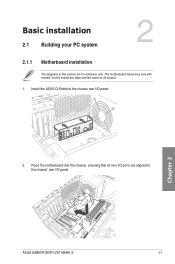
Install the ASUS Q-Shield to the chassis' rear I /O panel. 2. Place the motherboard into the chassis, ensuring that its rear I/O ports are aligned to the chassis rear I /O panel. Chapter 2: Basic installation Basic installation 2.1 Building your PC system 2 2.1.1 Motherboard installation The diagrams in this section are for all models. 1. Chapter 2 ASUS SABERTOOTH Z97 MARK S 2-1 The motherboard layout may vary with models, but the installation steps are the same for reference only.
Install the ASUS Q-Shield to the chassis' rear I /O panel. 2. Place the motherboard into the chassis, ensuring that its rear I/O ports are aligned to the chassis rear I /O panel. Chapter 2: Basic installation Basic installation 2.1 Building your PC system 2 2.1.1 Motherboard installation The diagrams in this section are for all models. 1. Chapter 2 ASUS SABERTOOTH Z97 MARK S 2-1 The motherboard layout may vary with models, but the installation steps are the same for reference only.


