

User Guide
Page 3
...SABERTOOTH Z97 MARK 2 specifications summary ix Package contents...xiii Installation tools and components xiv Chapter 1: Product Introduction 1.1 Special features 1-1 1.1.1 Product highlights 1-1 1.1.2 "Ultimate COOL" Thermal Solutions 1-2 1.1.3 "TUF Engine" Power Design 1-3 1.1.4 "Safe & Stable!" Guardian Angel 1-3 1.1.5 ASUS EZ DIY 1-4 1.1.6 ASUS... CPU installation 2-3 2.1.3 CPU heatsink and fan assembly installation 2-4 2.1.4 DIMM installation 2-6 2.1.5 ATX Power connection 2-7 2.1.6 SATA device connection 2-8 2.1.7 Front I/O Connector 2-9 2.1.8 Expansion Card ...
...SABERTOOTH Z97 MARK 2 specifications summary ix Package contents...xiii Installation tools and components xiv Chapter 1: Product Introduction 1.1 Special features 1-1 1.1.1 Product highlights 1-1 1.1.2 "Ultimate COOL" Thermal Solutions 1-2 1.1.3 "TUF Engine" Power Design 1-3 1.1.4 "Safe & Stable!" Guardian Angel 1-3 1.1.5 ASUS EZ DIY 1-4 1.1.6 ASUS... CPU installation 2-3 2.1.3 CPU heatsink and fan assembly installation 2-4 2.1.4 DIMM installation 2-6 2.1.5 ATX Power connection 2-7 2.1.6 SATA device connection 2-8 2.1.7 Front I/O Connector 2-9 2.1.8 Expansion Card ...

User Guide
Page 12
... Year Warranty manual (by region) 1 x User's manual WfM 2.0, DMI 2.7, WOL by PME, PXE Drivers Anti-virus software (OEM version) ASUS/TUF CPU-Z ASUS Utilities ATX form factor: 12.0 in . (30.5 cm x 24.4 cm) Specifications are subject to change without notice. Button 1 x DRCT (DirectKey)...24-pin EATX Power connector 8-pin EATX 12V Power connector System Panel (Q-Connector) 1 x MemOK! x 9.6 in . SABERTOOTH Z97 MARK 2 specifications summary Internal I/O connectors BIOS features Accessories Manageability Support DVD contents Form factor 2 x USB 3.0/2.0 connectors support additional 4 USB 3.0/2.0 ports...
... Year Warranty manual (by region) 1 x User's manual WfM 2.0, DMI 2.7, WOL by PME, PXE Drivers Anti-virus software (OEM version) ASUS/TUF CPU-Z ASUS Utilities ATX form factor: 12.0 in . (30.5 cm x 24.4 cm) Specifications are subject to change without notice. Button 1 x DRCT (DirectKey)...24-pin EATX Power connector 8-pin EATX 12V Power connector System Panel (Q-Connector) 1 x MemOK! x 9.6 in . SABERTOOTH Z97 MARK 2 specifications summary Internal I/O connectors BIOS features Accessories Manageability Support DVD contents Form factor 2 x USB 3.0/2.0 connectors support additional 4 USB 3.0/2.0 ports...

User Guide
Page 21
... due to static electricity. • Hold components by the edges to the motherboard, peripherals, or components. Chapter 1 ASUS SABERTOOTH Z97 MARK 2 1-7 1.2 Motherboard overview 1.2.1 Before you proceed Take note of the following precautions before touching any component, ensure that the ATX power supply is switched off or the power cord is detached from the power supply.
... due to static electricity. • Hold components by the edges to the motherboard, peripherals, or components. Chapter 1 ASUS SABERTOOTH Z97 MARK 2 1-7 1.2 Motherboard overview 1.2.1 Before you proceed Take note of the following precautions before touching any component, ensure that the ATX power supply is switched off or the power cord is detached from the power supply.
User Guide
Page 23
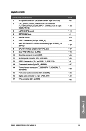
ATX power connectors (24-pin EATXPWR, 8-pin EATX12V) 2. CPU Over Voltage jumper (3-pin CPU_OV) 9. Thermal sensor connectors (T_SENSOR1, T_SENSOR2, T_ SENSOR3) 15. Digital audio connector (4-1 pin SPDIF_OUT) 17. Intel® Z97 Serial ATA 6.0 Gb/s connectors (7-pin SATA6G_1-6 [brown]) ...1-34 1-32 1-10 1-11 1-25 1-30 1-29 1-27 1-26 1-36 1-35 1-31 1-37 1-33 1-33 1-30 1-36 Chapter 1 ASUS SABERTOOTH Z97 MARK 2 1-9 Layout contents Connectors/Jumpers/Slots 1. CPU, optional, chassis, and assistant fan connectors (4-pin CPU_FAN; 4-pin CPU_OPT; 4-pin CHA_FAN1-4; 3-pin ...
ATX power connectors (24-pin EATXPWR, 8-pin EATX12V) 2. CPU Over Voltage jumper (3-pin CPU_OV) 9. Thermal sensor connectors (T_SENSOR1, T_SENSOR2, T_ SENSOR3) 15. Digital audio connector (4-1 pin SPDIF_OUT) 17. Intel® Z97 Serial ATA 6.0 Gb/s connectors (7-pin SATA6G_1-6 [brown]) ...1-34 1-32 1-10 1-11 1-25 1-30 1-29 1-27 1-26 1-36 1-35 1-31 1-37 1-33 1-33 1-30 1-36 Chapter 1 ASUS SABERTOOTH Z97 MARK 2 1-9 Layout contents Connectors/Jumpers/Slots 1. CPU, optional, chassis, and assistant fan connectors (4-pin CPU_FAN; 4-pin CPU_OPT; 4-pin CHA_FAN1-4; 3-pin ...

User Guide
Page 48
... configured system, we recommend that you use a power supply unit (PSU) that you want to use a PSU with a higher power output when configuring a system with ATX 12 V Specification 2.0 (or later version) and provides a minimum power of 350 W. • DO NOT forget to connect the 4-pin/8-pin EATX12 V power plug. The ...may not boot up if the power is inadequate. • If you use two or more power-consuming devices. The power supply plugs are for ATX power supply plugs. ATX power connectors (24-pin EATXPWR; 8-pin EATX12V) These connectors are designed to ensure the system stability.
... configured system, we recommend that you use a power supply unit (PSU) that you want to use a PSU with a higher power output when configuring a system with ATX 12 V Specification 2.0 (or later version) and provides a minimum power of 350 W. • DO NOT forget to connect the 4-pin/8-pin EATX12 V power plug. The ...may not boot up if the power is inadequate. • If you use two or more power-consuming devices. The power supply plugs are for ATX power supply plugs. ATX power connectors (24-pin EATXPWR; 8-pin EATX12V) These connectors are designed to ensure the system stability.

User Guide
Page 49
...to the HDD. • System warning speaker (4-pin SPEAKER) This 4-pin connector is for the chassis-mounted reset button for the system power LED. ASUS SABERTOOTH Z97 MARK 2 1-35 Chapter 1 Connect the chassis power LED cable to this connector. System panel connector (20-8 pin PANEL) This connector supports several chassis-.... The system power LED lights up or flashes when data is read from or written to hear system beeps and warnings. • ATX power button/soft-off mode depending on the system power, and blinks when the system is in sleep or soft-off button (2-pin ...
...to the HDD. • System warning speaker (4-pin SPEAKER) This 4-pin connector is for the chassis-mounted reset button for the system power LED. ASUS SABERTOOTH Z97 MARK 2 1-35 Chapter 1 Connect the chassis power LED cable to this connector. System panel connector (20-8 pin PANEL) This connector supports several chassis-.... The system power LED lights up or flashes when data is read from or written to hear system beeps and warnings. • ATX power button/soft-off mode depending on the system power, and blinks when the system is in sleep or soft-off button (2-pin ...

User Guide
Page 59
2.1.5 ATX Power connection OR OR ASUS SABERTOOTH Z97 MARK 2 2-7 Chapter 2
2.1.5 ATX Power connection OR OR ASUS SABERTOOTH Z97 MARK 2 2-7 Chapter 2

User Guide
Page 68
...devices (starting with a surge protector. 5. The system then runs the power-on . Check the jumper settings and connections or call your monitor complies with ATX power supplies, the system LED lights up when you do not see anything within 30 seconds from orange to put the system on sleep mode... the BIOS Setup. Turn on , hold down the key to the power connector at the back of the BIOS setting. If you press the ATX power button. Press the power switch for less than four seconds to disabled No keyboard detected No memory detected No VGA detected Hardware component failure 7....
...devices (starting with a surge protector. 5. The system then runs the power-on . Check the jumper settings and connections or call your monitor complies with ATX power supplies, the system LED lights up when you do not see anything within 30 seconds from orange to put the system on sleep mode... the BIOS Setup. Turn on , hold down the key to the power connector at the back of the BIOS setting. If you press the ATX power button. Press the power switch for less than four seconds to disabled No keyboard detected No memory detected No VGA detected Hardware component failure 7....

