User Manual
Page 4
... 2-39 2.9 Onboard LEDs 2-40 2.10 Starting up for the first time 2-41 2.11 Turning off the computer 2-41 Chapter 3: BIOS setup 3.1 Knowing BIOS 3-1 3.2 Updating BIOS 3-1 3.2.1 ASUS Update utility 3-2 3.2.2 ASUS EZ Flash 2 utility 3-4 3.2.3 ASUS CrashFree BIOS 3 utility 3-5 3.2.4 ASUS BIOS Updater 3-5 3.3 BIOS setup program 3-8 3.3.1 BIOS menu screen 3-8 3.3.2 Menu bar 3-8 3.3.3 Navigation keys 3-9 3.3.4 Menu items 3-9 3.3.5 Submenu items 3-9 3.3.6 Configuration fields 3-9 3.3.7 Pop-up window 3-9 3.3.8 Scroll bar 3-9 3.3.9 General...
... 2-39 2.9 Onboard LEDs 2-40 2.10 Starting up for the first time 2-41 2.11 Turning off the computer 2-41 Chapter 3: BIOS setup 3.1 Knowing BIOS 3-1 3.2 Updating BIOS 3-1 3.2.1 ASUS Update utility 3-2 3.2.2 ASUS EZ Flash 2 utility 3-4 3.2.3 ASUS CrashFree BIOS 3 utility 3-5 3.2.4 ASUS BIOS Updater 3-5 3.3 BIOS setup program 3-8 3.3.1 BIOS menu screen 3-8 3.3.2 Menu bar 3-8 3.3.3 Navigation keys 3-9 3.3.4 Menu items 3-9 3.3.5 Submenu items 3-9 3.3.6 Configuration fields 3-9 3.3.7 Pop-up window 3-9 3.3.8 Scroll bar 3-9 3.3.9 General...
User Manual
Page 6
... information 4-1 4.2.1 Running the support DVD 4-1 4.2.2 Obtaining the software manuals 4-2 4.3 Software information 4-3 4.3.1 ASUS PC Probe II 4-3 4.3.2 ASUS Fan Xpert 4-4 4.3.3 VIA® High Definition Audio utility 4-5 4.3.4 ASUS Drive Xpert 4-6 4.3.5 ASUS T.Probe 4-7 4.4 RAID configurations 4-8 4.4.1 RAID definitions 4-8 4.4.2 Installing Serial ATA hard disks 4-9 4.4.3 Setting the RAID item in BIOS 4-9 4.4.4 Intel® Matrix Storage Manager option ROM utility 4-9 4.5 Creating a RAID driver...
... information 4-1 4.2.1 Running the support DVD 4-1 4.2.2 Obtaining the software manuals 4-2 4.3 Software information 4-3 4.3.1 ASUS PC Probe II 4-3 4.3.2 ASUS Fan Xpert 4-4 4.3.3 VIA® High Definition Audio utility 4-5 4.3.4 ASUS Drive Xpert 4-6 4.3.5 ASUS T.Probe 4-7 4.4 RAID configurations 4-8 4.4.1 RAID definitions 4-8 4.4.2 Installing Serial ATA hard disks 4-9 4.4.3 Setting the RAID item in BIOS 4-9 4.4.4 Intel® Matrix Storage Manager option ROM utility 4-9 4.5 Creating a RAID driver...
User Manual
Page 9
... This chapter describes the features of the standard package. Refer to change system settings through the BIOS Setup menus. ASUS websites The ASUS website provides updated information on the motherboard. • Chapter 3: BIOS setup This chapter tells how to the ASUS contact information. 2. ix About this guide is organized This guide contains the following sources for...
... This chapter describes the features of the standard package. Refer to change system settings through the BIOS Setup menus. ASUS websites The ASUS website provides updated information on the motherboard. • Chapter 3: BIOS setup This chapter tells how to the ASUS contact information. 2. ix About this guide is organized This guide contains the following sources for...
User Manual
Page 12
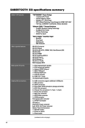
...for 3VSB/1.8V/1.05V - Fan Frame - EMI Eliminator ASUS Q-Connector ASUS Q-Shield ASUS Q-LED (CPU, DRAM, VGA, Boot Device LED) ASUS Q-Slot ASUS Q-DIMM ASUS CrashFree BIOS 3 ASUS EZ Flash 2 ASUS MyLogo 2™ ASUS O.C. SABERTOOTH 55i specifications summary ASUS TUF features Other special features Back panel I/O ports Internal...Mem Fan connector 1 x IEEE1394a connector 1 x COM connector Front panel audio connector 1 x S/PDIF Out header CD audio in 24-pin ATX Power connector 8-pin EATX 12V Power connector System Panel (Q-Connector) 1 x MemOK! TUF Cap. & MOSFET (certified by military-standard) "...
...for 3VSB/1.8V/1.05V - Fan Frame - EMI Eliminator ASUS Q-Connector ASUS Q-Shield ASUS Q-LED (CPU, DRAM, VGA, Boot Device LED) ASUS Q-Slot ASUS Q-DIMM ASUS CrashFree BIOS 3 ASUS EZ Flash 2 ASUS MyLogo 2™ ASUS O.C. SABERTOOTH 55i specifications summary ASUS TUF features Other special features Back panel I/O ports Internal...Mem Fan connector 1 x IEEE1394a connector 1 x COM connector Front panel audio connector 1 x S/PDIF Out header CD audio in 24-pin ATX Power connector 8-pin EATX 12V Power connector System Panel (Q-Connector) 1 x MemOK! TUF Cap. & MOSFET (certified by military-standard) "...
User Manual
Page 13
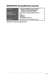
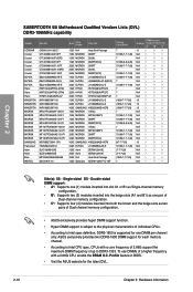
SABERTOOTH 55i specifications summary BIOS features Manageability Support DVD contents Form factor 16 Mb Flash ROM, AMI BIOS, PnP, DMI 2.0, WfM 2.0, SM BIOS 2.5, ACPI 2.0a, Multi-language BIOS, ASUS EZ Flash 2, ASUS CrashFree BIOS 3 WfM 2.0, DMI 2.0, WOL by PME, WOR by PME, PXE Drivers ASUS Utilities ASUS Update Anti-virus software (OEM version) ATX form factor: 12 in . (30.5 cm x 24.4 cm) *Specifications are subject to change without notice. xiii x 9.6 in .
SABERTOOTH 55i specifications summary BIOS features Manageability Support DVD contents Form factor 16 Mb Flash ROM, AMI BIOS, PnP, DMI 2.0, WfM 2.0, SM BIOS 2.5, ACPI 2.0a, Multi-language BIOS, ASUS EZ Flash 2, ASUS CrashFree BIOS 3 WfM 2.0, DMI 2.0, WOL by PME, WOR by PME, PXE Drivers ASUS Utilities ASUS Update Anti-virus software (OEM version) ATX form factor: 12 in . (30.5 cm x 24.4 cm) *Specifications are subject to change without notice. xiii x 9.6 in .
User Manual
Page 18
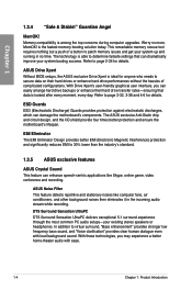
...Filter This feature detects repetitive and stationary noises like Skype, online game, video conference and recording. ASUS Drive Xpert Without BIOS setups, the ASUS exclusive Drive Xpert is ideal for anyone who needs to page 2-24 for details. Refer to ...determine failsafe settings that data is the fastest memory booting solution today. The ASUS exclusive Anti-Static chip and circuit design, and the I/O shield provide four times better protection and ensure the motherboard...
...Filter This feature detects repetitive and stationary noises like Skype, online game, video conference and recording. ASUS Drive Xpert Without BIOS setups, the ASUS exclusive Drive Xpert is ideal for anyone who needs to page 2-24 for details. Refer to ...determine failsafe settings that data is the fastest memory booting solution today. The ASUS exclusive Anti-Static chip and circuit design, and the I/O shield provide four times better protection and ensure the motherboard...
User Manual
Page 19
... or disconnect the chassis front panel cables to conveniently store or load multiple BIOS settings. The localized BIOS setup menu helps you to the motherboard. ASUS SABERTOOTH 55i 1-5 Refer to page 2-39 for details. This unique module eliminates the trouble of your screen. ASUS EZ-Flash 2 ASUS EZ Flash 2 is a user-friendly utility that allows you configure your...
... or disconnect the chassis front panel cables to conveniently store or load multiple BIOS settings. The localized BIOS setup menu helps you to the motherboard. ASUS SABERTOOTH 55i 1-5 Refer to page 2-39 for details. This unique module eliminates the trouble of your screen. ASUS EZ-Flash 2 ASUS EZ Flash 2 is a user-friendly utility that allows you configure your...
User Manual
Page 31
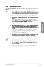
... with a core frequency of 2.66G support the maximum DIMM frequency of up of 512Mb (64MB) chips or less (Memory chip capacity counts in BIOS. • Always install DIMMs with a 2.66G CPU, enable the DRAM O.C. Use a maximum of memory, we recommend that you install 4GB ...same CAS latency. ASUS SABERTOOTH 55i 2-11 Chapter 2 2.4.2 Memory configurations You may install 1GB, 2GB and 4GB unbuffered and non‑ECC DDR3 DIMMs into the DIMM sockets. • You may operate at a lower frequency than the vendor-marked value. For more memory on the motherboard. Profile feature in...
... with a core frequency of 2.66G support the maximum DIMM frequency of up of 512Mb (64MB) chips or less (Memory chip capacity counts in BIOS. • Always install DIMMs with a 2.66G CPU, enable the DRAM O.C. Use a maximum of memory, we recommend that you install 4GB ...same CAS latency. ASUS SABERTOOTH 55i 2-11 Chapter 2 2.4.2 Memory configurations You may install 1GB, 2GB and 4GB unbuffered and non‑ECC DDR3 DIMMs into the DIMM sockets. • You may operate at a lower frequency than the vendor-marked value. For more memory on the motherboard. Profile feature in...
User Manual
Page 32
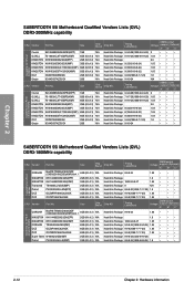
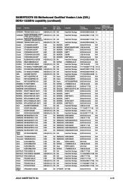
...• Gingle 9CAASS37AZZ01D1 2GB N/A Heat-Sink Package 9-9-9-24 •• • SABERTOOTH 55i Motherboard Qualified Vendors Lists (QVL) DDR3-1800MHz capability CPU Vendor Part No. Timing Lable(Bios) DIMM socket Voltage support (Optional) A* B* C* CORSAIR BoxP/N:TW3X4G1800C8DF (CM3X2G1800C8D)(XMP)Ver4... • CPU Vendor Part No. Size Chip Brand Chip NO. Chapter 2 SABERTOOTH 55i Motherboard Qualified Vendors Lists (QVL) DDR3-2000MHz capability CPU Vendor Part No. Timing Lable(Bios) DIMM socket Voltage support (Optional) A* B* C* Crucial BL12864BE2009.8SFB3(EPP) ...
...• Gingle 9CAASS37AZZ01D1 2GB N/A Heat-Sink Package 9-9-9-24 •• • SABERTOOTH 55i Motherboard Qualified Vendors Lists (QVL) DDR3-1800MHz capability CPU Vendor Part No. Timing Lable(Bios) DIMM socket Voltage support (Optional) A* B* C* CORSAIR BoxP/N:TW3X4G1800C8DF (CM3X2G1800C8D)(XMP)Ver4... • CPU Vendor Part No. Size Chip Brand Chip NO. Chapter 2 SABERTOOTH 55i Motherboard Qualified Vendors Lists (QVL) DDR3-2000MHz capability CPU Vendor Part No. Timing Lable(Bios) DIMM socket Voltage support (Optional) A* B* C* Crucial BL12864BE2009.8SFB3(EPP) ...
User Manual
Page 33
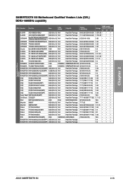
Capability for CPU at 2.66GHz Chapter 2 SABERTOOTH 55i Motherboard Qualified Vendors Lists (QVL) DDR3-1600MHz capability CPU Vendor Part No. Timing Lable(Bios) A-DATA AD31600E001GMU 3GB (Kit of 3) N/A Heat-Sink Package 8-8-8-24(1333-9-9-9-24) A-DATA AD31600F002GMU(XMP) 6GB (Kit of 3) N/A Heat-Sink Package 7-7-7-20(1333-9-9-9-...; • • 1.65 • • • 1.9 •• 2.0 •• 1.65 • • • N/A ••• 1.9 ••• 1.9 ••• ASUS SABERTOOTH 55i 2-13 Size Chip Brand Chip NO.
Capability for CPU at 2.66GHz Chapter 2 SABERTOOTH 55i Motherboard Qualified Vendors Lists (QVL) DDR3-1600MHz capability CPU Vendor Part No. Timing Lable(Bios) A-DATA AD31600E001GMU 3GB (Kit of 3) N/A Heat-Sink Package 8-8-8-24(1333-9-9-9-24) A-DATA AD31600F002GMU(XMP) 6GB (Kit of 3) N/A Heat-Sink Package 7-7-7-20(1333-9-9-9-...; • • 1.65 • • • 1.9 •• 2.0 •• 1.65 • • • N/A ••• 1.9 ••• 1.9 ••• ASUS SABERTOOTH 55i 2-13 Size Chip Brand Chip NO.
User Manual
Page 34
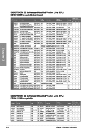
...; ••• 1.9 ••• 1.9 •• 1.9 ••• SABERTOOTH 55i Motherboard Qualified Vendors Lists (QVL) DDR3-1333MHz capability Vendor Part No. Timing Lable(Bios) DIMM socket Voltage support (Optional) A* B* C* AD30908C8D-15IG (1333-9-9-9-24) N/A •• ...Chapter 2: Hardware information Size Chip Brand Chip NO. Chapter 2 SABERTOOTH 55i Motherboard Qualified Vendors Lists (QVL) DDR3-1600MHz capability (continued) CPU Vendor Part No. Timing Lable(Bios) Capability for CPU at 2.8 and 2.93GHz A-DATA AD31600E001GMU 3GB ...
...; ••• 1.9 ••• 1.9 •• 1.9 ••• SABERTOOTH 55i Motherboard Qualified Vendors Lists (QVL) DDR3-1333MHz capability Vendor Part No. Timing Lable(Bios) DIMM socket Voltage support (Optional) A* B* C* AD30908C8D-15IG (1333-9-9-9-24) N/A •• ...Chapter 2: Hardware information Size Chip Brand Chip NO. Chapter 2 SABERTOOTH 55i Motherboard Qualified Vendors Lists (QVL) DDR3-1600MHz capability (continued) CPU Vendor Part No. Timing Lable(Bios) Capability for CPU at 2.8 and 2.93GHz A-DATA AD31600E001GMU 3GB ...
User Manual
Page 35
Chapter 2 SABERTOOTH 55i Motherboard Qualified Vendors Lists (QVL) DDR3-1333MHz capability (continued) Vendor Part No. Size SS/ Chip DS Brand Chip NO. Timing Lable(Bios) Voltage CORSAIR TR3X3G1333C9 (Ver2.1) 3GB (Kit of 3) SS CORSAIR BoxP/N:TWIN3X2048-1333C9 (CM3X1024-1333C9)Ver1.1 2GB (Kit of 2) DS CORSAIR BoxP/N:TW3X4G1333C9DHX (CM3X2048-... 9-9-9-24(1066-7-7-7-20) 1.65 9(1333-9-9-9-24) N/A DIMM socket support (Optional) A* B* C* •• • •• • •• •• • •• • ASUS SABERTOOTH 55i 2-15
Chapter 2 SABERTOOTH 55i Motherboard Qualified Vendors Lists (QVL) DDR3-1333MHz capability (continued) Vendor Part No. Size SS/ Chip DS Brand Chip NO. Timing Lable(Bios) Voltage CORSAIR TR3X3G1333C9 (Ver2.1) 3GB (Kit of 3) SS CORSAIR BoxP/N:TWIN3X2048-1333C9 (CM3X1024-1333C9)Ver1.1 2GB (Kit of 2) DS CORSAIR BoxP/N:TW3X4G1333C9DHX (CM3X2048-... 9-9-9-24(1066-7-7-7-20) 1.65 9(1333-9-9-9-24) N/A DIMM socket support (Optional) A* B* C* •• • •• • •• •• • •• • ASUS SABERTOOTH 55i 2-15
User Manual
Page 36
SABERTOOTH 55i Motherboard Qualified Vendors Lists (QVL) DDR3-1066MHz capability Vendor Part No. Profile feature in BIOS. • Visit the ASUS website for each memory channel. • According to DDR3-1333. To use DIMMs of individual CPUs. ... K4B2G0846B-HCF8 2GB ELPIDA J1108BABG-AE-E 1GB Asint DDRIII1208-AE 2GB Asint DDRIII1208-AE 2GB N/A Heat-Sink Package 1GB Qimonda IDSH51-03A1F1C-10F Timing Lable(Bios) 7 7(1066-7-7-7-20) 7 7(1066-9-9-9-25) 7(1066-7-7-7-20) 7 7(1066-7-7-7-20) 7(1066-7-7-7-20) 7 7(1066-7-7-7-20) 7 7 7 (1066-7-7-7-20) (1066-7-7-7-20) (1066-7-7-7-20) 7 7(...
SABERTOOTH 55i Motherboard Qualified Vendors Lists (QVL) DDR3-1066MHz capability Vendor Part No. Profile feature in BIOS. • Visit the ASUS website for each memory channel. • According to DDR3-1333. To use DIMMs of individual CPUs. ... K4B2G0846B-HCF8 2GB ELPIDA J1108BABG-AE-E 1GB Asint DDRIII1208-AE 2GB Asint DDRIII1208-AE 2GB N/A Heat-Sink Package 1GB Qimonda IDSH51-03A1F1C-10F Timing Lable(Bios) 7 7(1066-7-7-7-20) 7 7(1066-9-9-9-25) 7(1066-7-7-7-20) 7 7(1066-7-7-7-20) 7(1066-7-7-7-20) 7 7(1066-7-7-7-20) 7 7 7 (1066-7-7-7-20) (1066-7-7-7-20) (1066-7-7-7-20) 7 7(...
User Manual
Page 38
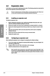
... adding or removing expansion cards. Ensure to the table on BIOS setup. 2. Remove the bracket opposite the slot that they support. Chapter 2 2.5 Expansion slots In the future, you may cause you physical injury and damage motherboard components. 2.5.1 Installing an expansion card To install an expansion ...card: 1. Remove the system unit cover (if your motherboard is completely seated on the system and change the necessary BIOS settings, if any. Keep the screw for the card. 2. Turn on the slot. 5. The following subsections ...
... adding or removing expansion cards. Ensure to the table on BIOS setup. 2. Remove the bracket opposite the slot that they support. Chapter 2 2.5 Expansion slots In the future, you may cause you physical injury and damage motherboard components. 2.5.1 Installing an expansion card To install an expansion ...card: 1. Remove the system unit cover (if your motherboard is completely seated on the system and change the necessary BIOS settings, if any. Keep the screw for the card. 2. Turn on the slot. 5. The following subsections ...
User Manual
Page 42
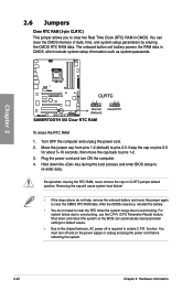
... 2. Move the jumper cap from pins 1-2 (default) to overclocking, use the C.P.R. (CPU Parameter Recall) feature. Shut down the key during the boot process and enter BIOS setup to re-enter data. Removing the cap will cause system boot failure! • If the steps above do not need to clear the RTC... Real Time Clock (RTC) RAM in CMOS, which include system setup information such as system passwords. Hold down and reboot the system so the BIOS can clear the CMOS memory of date, time, and system setup parameters by erasing the CMOS RTC RAM data. The onboard button cell battery powers...
... 2. Move the jumper cap from pins 1-2 (default) to overclocking, use the C.P.R. (CPU Parameter Recall) feature. Shut down the key during the boot process and enter BIOS setup to re-enter data. Removing the cap will cause system boot failure! • If the steps above do not need to clear the RTC... Real Time Clock (RTC) RAM in CMOS, which include system setup information such as system passwords. Hold down and reboot the system so the BIOS can clear the CMOS memory of date, time, and system setup parameters by erasing the CMOS RTC RAM data. The onboard button cell battery powers...
User Manual
Page 44
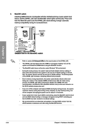
... off the system and reinstall the DIMM before using the MemOK! switch until the DRAM_LED starts blinking to the latest BIOS version from the ASUS website at www.asus.com after the whole tuning process, the DRAM_LED lights continuously. switch does not function under Windows® OS environment.... 5-10 seconds. • If your system fail to boot due to section 2.9 Onboard LEDs for successful boot. Replace the DIMMs with the motherboard may cause system boot failure, and the DRAM_LED near the MemOK! switch lights continuously. function. • The MemOK! A messgae will appear ...
... off the system and reinstall the DIMM before using the MemOK! switch until the DRAM_LED starts blinking to the latest BIOS version from the ASUS website at www.asus.com after the whole tuning process, the DRAM_LED lights continuously. switch does not function under Windows® OS environment.... 5-10 seconds. • If your system fail to boot due to section 2.9 Onboard LEDs for successful boot. Replace the DIMMs with the motherboard may cause system boot failure, and the DRAM_LED near the MemOK! switch lights continuously. function. • The MemOK! A messgae will appear ...

User Manual
Page 45
Ensure your system functions well under the highest BIOS voltage settings before you change the switch settings. Chapter 2 4. Read the following information before you change the setting of this switch. • According to ...to protect the CPU. • The system may need a better cooling system (for extra-high overvoltage ability, use the BIOS items first to enable or disable the advanced DRAM overvoltage settings in BIOS. ASUS SABERTOOTH 55i 2-25 DRAM overvoltage setting switch (OV_DRAM) This switch allows you change the settings for example, a water-cooling system) to...
Ensure your system functions well under the highest BIOS voltage settings before you change the switch settings. Chapter 2 4. Read the following information before you change the setting of this switch. • According to ...to protect the CPU. • The system may need a better cooling system (for extra-high overvoltage ability, use the BIOS items first to enable or disable the advanced DRAM overvoltage settings in BIOS. ASUS SABERTOOTH 55i 2-25 DRAM overvoltage setting switch (OV_DRAM) This switch allows you change the settings for example, a water-cooling system) to...
User Manual
Page 46
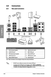
... insert a different connector to the external SATA port. • To enable external SATA device hot-plugging, set the J-Micron eSATA/PATA Controller item in the BIOS setting to section 3.6.3 Onboard Devices Configuration for details. 2-26 Chapter 2: Hardware information
... insert a different connector to the external SATA port. • To enable external SATA device hot-plugging, set the J-Micron eSATA/PATA Controller item in the BIOS setting to section 3.6.3 Onboard Devices Configuration for details. 2-26 Chapter 2: Hardware information
User Manual
Page 51
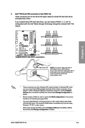
Chapter 2 • These connectors are set using Serial ATA hard disk drives. ASUS SABERTOOTH 55i 2-31 In Standard IDE mode, you are for the Serial ATA signal cables for Serial ATA hard disk drives and optical disc drives. See section 3.4.2 ... drives to these connectors, set , refer to section 4.4 RAID configurations or the manual bundled in the BIOS to [AHCI]. See section 3.4.2 Storage Configuration for details. • Before creating a RAID set the Configure SATA as in the motherboard support DVD. • You must install Windows® XP Service Pack 2 or later version before...
Chapter 2 • These connectors are set using Serial ATA hard disk drives. ASUS SABERTOOTH 55i 2-31 In Standard IDE mode, you are for the Serial ATA signal cables for Serial ATA hard disk drives and optical disc drives. See section 3.4.2 ... drives to these connectors, set , refer to section 4.4 RAID configurations or the manual bundled in the BIOS to [AHCI]. See section 3.4.2 Storage Configuration for details. • Before creating a RAID set the Configure SATA as in the motherboard support DVD. • You must install Windows® XP Service Pack 2 or later version before...
User Manual
Page 56
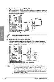
...end of the front panel audio I /O module that you connect a high-definition front panel audio module to this connector to avail of the motherboard's high-definition audio capability. • If you want to connect a high-definition front panel audio module to this connector, then install the ...The S/PDIF module is for a chassis-mounted front panel audio I /O module cable to this connector, set the Front Panel Type item in the BIOS setup to this connector. • We recommend that supports either HD Audio or legacy AC`97 audio standard. Digital audio connector (4-1 pin SPDIF_OUT) ...
...end of the front panel audio I /O module that you connect a high-definition front panel audio module to this connector to avail of the motherboard's high-definition audio capability. • If you want to connect a high-definition front panel audio module to this connector, then install the ...The S/PDIF module is for a chassis-mounted front panel audio I /O module cable to this connector, set the Front Panel Type item in the BIOS setup to this connector. • We recommend that supports either HD Audio or legacy AC`97 audio standard. Digital audio connector (4-1 pin SPDIF_OUT) ...


