User Guide
Page 14
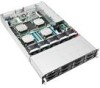
...Product introduction You may have to Chapter 7 for the following items. Model Name Chassis Motherboard Component Accessories Optional Items RS920-E7/RS8 RS926-E7/RS8 ASUS R21B 2U Rackmount Chassis ASUS Z9PX-Q32 Series Server Board 1 x 1620W 80PLUS Platinum Redundant Power Supply 1 x SATA Backplane with 8 x SATA...Supply Power Distribution Board 5 x System Fans (80mm) 1 x User's Guide 1 x RS92x-E7/RS8 Series Support DVD 1 x Bag of Screws 1 x Friction Rail Kit CPU Heatsink Anti-virus CD *ASUS System Web-based Management * The system does not include a USB floppy drive. If any of...
...Product introduction You may have to Chapter 7 for the following items. Model Name Chassis Motherboard Component Accessories Optional Items RS920-E7/RS8 RS926-E7/RS8 ASUS R21B 2U Rackmount Chassis ASUS Z9PX-Q32 Series Server Board 1 x 1620W 80PLUS Platinum Redundant Power Supply 1 x SATA Backplane with 8 x SATA...Supply Power Distribution Board 5 x System Fans (80mm) 1 x User's Guide 1 x RS92x-E7/RS8 Series Support DVD 1 x Bag of Screws 1 x Friction Rail Kit CPU Heatsink Anti-virus CD *ASUS System Web-based Management * The system does not include a USB floppy drive. If any of...
User Guide
Page 15
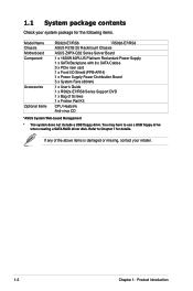
1.2 Serial number label Before requesting support from the ASUS Technical Support team, you must take note of the product, ASUS Technical Support team members can then offer a quicker and satisfying solution to your problems. RS92x -E7/RS8 xxS0xxxxxxxxxx ASUS RS920-E7/RS8; With the correct serial number of the product's serial number containing 14 characters such as xxS0xxxxxxxxxx. RS926-E7/RS8 1-3 See the figure below.
1.2 Serial number label Before requesting support from the ASUS Technical Support team, you must take note of the product, ASUS Technical Support team members can then offer a quicker and satisfying solution to your problems. RS92x -E7/RS8 xxS0xxxxxxxxxx ASUS RS920-E7/RS8; With the correct serial number of the product's serial number containing 14 characters such as xxS0xxxxxxxxxx. RS926-E7/RS8 1-3 See the figure below.
User Guide
Page 16
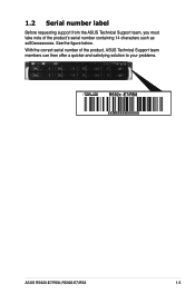
Model Name Processor Support Core Logic Memory Total Slots Capacity RS926-E7/RS8 RS920-E7/RS8 4 x LGA 2011 socket Intel® Xeon® Processor E5-4600 Product Family (up to 130W) Intel® QuickPath Interconnect (QPI) 6.4/7.2/8.0 GT/s... RAID card 8 x Hot-swappable 3.5" HDD Bays (continued on the next page) 1-4 Chapter 1: Product introduction 1.3 System specifications The ASUS RS920-E7/RS8 and RS926-E7/RS8 are servers featuring the ASUS Z9PX-Q32 Series server board.The server supports the Intel® Xeon® E5-4600 processor family, plus other latest technologies through the...
Model Name Processor Support Core Logic Memory Total Slots Capacity RS926-E7/RS8 RS920-E7/RS8 4 x LGA 2011 socket Intel® Xeon® Processor E5-4600 Product Family (up to 130W) Intel® QuickPath Interconnect (QPI) 6.4/7.2/8.0 GT/s... RAID card 8 x Hot-swappable 3.5" HDD Bays (continued on the next page) 1-4 Chapter 1: Product introduction 1.3 System specifications The ASUS RS920-E7/RS8 and RS926-E7/RS8 are servers featuring the ASUS Z9PX-Q32 Series server board.The server supports the Intel® Xeon® E5-4600 processor family, plus other latest technologies through the...
User Guide
Page 17
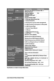
ASUS RS920-E7/RS8; RS926-E7/RS8 1-5 Model Name Networking LAN Infiniband Graphic VGA Auxiliary Storage Device Bay Onboard I/O OS Support Anti-virus Software Management Solution Software Out of Band Management Dimension (L x W x H) Net Weight (kg) Power Supply Power Rating Environment RS926-E7/RS8 RS920-E7/RS8 Quad Port Intel Ethernet Controller i350 + 1 Management port Single port Mellanox N/A ConnectX-3 FDR InfiniteBand with QSFP...
ASUS RS920-E7/RS8; RS926-E7/RS8 1-5 Model Name Networking LAN Infiniband Graphic VGA Auxiliary Storage Device Bay Onboard I/O OS Support Anti-virus Software Management Solution Software Out of Band Management Dimension (L x W x H) Net Weight (kg) Power Supply Power Rating Environment RS926-E7/RS8 RS920-E7/RS8 Quad Port Intel Ethernet Controller i350 + 1 Management port Single port Mellanox N/A ConnectX-3 FDR InfiniteBand with QSFP...
User Guide
Page 19
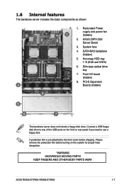
.... 1.6 Internal features The barebone server includes the basic components as shown. 1. ASUS Z9PX-Q32 Server Board 3. Connect a USB floppy disk drive to use a floppy disk. Redundant Power supply and power fan 8 1 (hidden) 8 8 2. System fans 4. Hot-swap HDD tray 2 1-8 (SAS and SATA) 6. RS926-E7/RS8 1-7 SATA/SAS backplane (hidden) 5. A protection film is pre-attached to...
.... 1.6 Internal features The barebone server includes the basic components as shown. 1. ASUS Z9PX-Q32 Server Board 3. Connect a USB floppy disk drive to use a floppy disk. Redundant Power supply and power fan 8 1 (hidden) 8 8 2. System fans 4. Hot-swap HDD tray 2 1-8 (SAS and SATA) 6. RS926-E7/RS8 1-7 SATA/SAS backplane (hidden) 5. A protection film is pre-attached to...
User Guide
Page 21
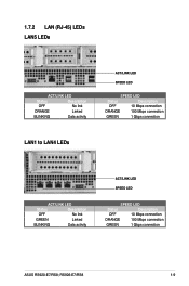
RS926-E7/RS8 1-9 1.7.2 LAN (RJ-45) LEDs LAN5 LEDs ACT/LINK LED Status Description OFF No link ORANGE Linked BLINKING Data activity ACT/LINK LED SPEED LED SPEED LED Status Description OFF 10 Mbps connection ORANGE 100 Mbps connection GREEN 1 Gbps connection LAN1 to LAN4 LEDs ACT/LINK LED Status Description OFF No link GREEN Linked BLINKING Data activity ACT/LINK LED SPEED LED SPEED LED Status Description OFF 10 Mbps connection ORANGE 100 Mbps connection GREEN 1 Gbps connection ASUS RS920-E7/RS8;
RS926-E7/RS8 1-9 1.7.2 LAN (RJ-45) LEDs LAN5 LEDs ACT/LINK LED Status Description OFF No link ORANGE Linked BLINKING Data activity ACT/LINK LED SPEED LED SPEED LED Status Description OFF 10 Mbps connection ORANGE 100 Mbps connection GREEN 1 Gbps connection LAN1 to LAN4 LEDs ACT/LINK LED Status Description OFF No link GREEN Linked BLINKING Data activity ACT/LINK LED SPEED LED SPEED LED Status Description OFF 10 Mbps connection ORANGE 100 Mbps connection GREEN 1 Gbps connection ASUS RS920-E7/RS8;
User Guide
Page 25
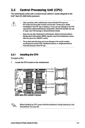
ASUS will shoulder the cost of the PnP cap. 2.2.1 Installing the CPU To install a CPU: 1. Before installing the CPU, ensure that the PnP cap is on the socket and the socket contacts are not bent. Locate the CPU socket on the motherboard. RS926-E7/RS8 2-3 Contact your retailer ...immediately if the PnP cap is missing, or if you and the load lever is on your left. ASUS RS920-E7/RS8; 2.2 Central Processing Unit (CPU) The motherboard comes with the cap ...
ASUS will shoulder the cost of the PnP cap. 2.2.1 Installing the CPU To install a CPU: 1. Before installing the CPU, ensure that the PnP cap is on the socket and the socket contacts are not bent. Locate the CPU socket on the motherboard. RS926-E7/RS8 2-3 Contact your retailer ...immediately if the PnP cap is missing, or if you and the load lever is on your left. ASUS RS920-E7/RS8; 2.2 Central Processing Unit (CPU) The motherboard comes with the cap ...
User Guide
Page 27
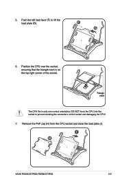
RS926-E7/RS8 2-5 Position the CPU over the socket, ensuring that the triangle mark is on the socket and damaging the CPU! 7. Triangle mark The CPU fits in only one correct orientation. Push the left load lever (F) to prevent bending the connectors on the top‑right corner of the socket. F G 6. I ). Remove the PnP cap (H) from the CPU socket and close the load plate (I H ASUS RS920-E7/RS8; DO NOT force the CPU into the socket to lift the load plate (G). 5.
RS926-E7/RS8 2-5 Position the CPU over the socket, ensuring that the triangle mark is on the socket and damaging the CPU! 7. Triangle mark The CPU fits in only one correct orientation. Push the left load lever (F) to prevent bending the connectors on the top‑right corner of the socket. F G 6. I ). Remove the PnP cap (H) from the CPU socket and close the load plate (I H ASUS RS920-E7/RS8; DO NOT force the CPU into the socket to lift the load plate (G). 5.
User Guide
Page 29
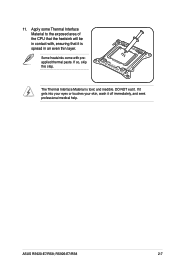
If so, skip this step. ASUS RS920-E7/RS8; Some heatsinks come with , ensuring that it is toxic and inedible. If it gets into your eyes or touches your skin, wash it . 11. The Thermal Interface Material is spread in contact with preapplied thermal paste. RS926-E7/RS8 2-7 Apply some Thermal Interface Material to the exposed area of the CPU that the heatsink will be in an even thin layer. DO NOT eat it off immediately, and seek professional medical help.
If so, skip this step. ASUS RS920-E7/RS8; Some heatsinks come with , ensuring that it is toxic and inedible. If it gets into your eyes or touches your skin, wash it . 11. The Thermal Interface Material is spread in contact with preapplied thermal paste. RS926-E7/RS8 2-7 Apply some Thermal Interface Material to the exposed area of the CPU that the heatsink will be in an even thin layer. DO NOT eat it off immediately, and seek professional medical help.
User Guide
Page 31
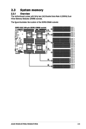
2.3 System memory 2.3.1 Overview The motherboard comes with thirty-two (32) Double Data Rate 3 (DDR3) Dual Inline Memory Modules (DIMM) sockets. The figure illustrates the location of the DDR3 DIMM sockets: ASUS RS920-E7/RS8; RS926-E7/RS8 2-9
2.3 System memory 2.3.1 Overview The motherboard comes with thirty-two (32) Double Data Rate 3 (DDR3) Dual Inline Memory Modules (DIMM) sockets. The figure illustrates the location of the DDR3 DIMM sockets: ASUS RS920-E7/RS8; RS926-E7/RS8 2-9
User Guide
Page 33
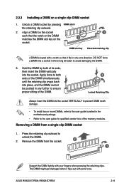
RS926-E7/RS8 2-11 DIMM slot key Unlocked retaining clip A DIMM is keyed with extra force. Press the retaining clip outward to the user guide for qualified vendor ... DIMM slot key on a single clip DIMM socket 1. Removing a DIMM from the socket. 2 1 Support the DIMM lightly with your fingers when pressing the retaining clips. ASUS RS920-E7/RS8; Align a DIMM on the socket 1 such that it fits in the motherboard package. • Refer to unlock the DIMM. 2. Remove the DIMM from a single...
RS926-E7/RS8 2-11 DIMM slot key Unlocked retaining clip A DIMM is keyed with extra force. Press the retaining clip outward to the user guide for qualified vendor ... DIMM slot key on a single clip DIMM socket 1. Removing a DIMM from the socket. 2 1 Support the DIMM lightly with your fingers when pressing the retaining clips. ASUS RS920-E7/RS8; Align a DIMM on the socket 1 such that it fits in the motherboard package. • Refer to unlock the DIMM. 2. Remove the DIMM from a single...
User Guide
Page 35
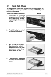
... of the bay. 3. Each side has three holes to the right, then pulling the tray lever outward. ASUS RS920-E7/RS8; Release a drive tray by pushing the spring lock to fit different types of hard disk drives. RS926-E7/RS8 2-13 To install a hot-swap SATAII/SAS HDD: spring lock 1. The hard disk drive installed on...
... of the bay. 3. Each side has three holes to the right, then pulling the tray lever outward. ASUS RS920-E7/RS8; Release a drive tray by pushing the spring lock to fit different types of hard disk drives. RS926-E7/RS8 2-13 To install a hot-swap SATAII/SAS HDD: spring lock 1. The hard disk drive installed on...
User Guide
Page 37
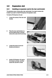
... remove it. 4. Install a PCI Express x16 card to the bracket as shown, and then secure the card with a riser card bracket. PCI Express x16 slot ASUS RS920-E7/RS8; RS926-E7/RS8 2-15 To install a PCI Express x16 card 1. 2.5 Expansion slot 2.5.1 Installing an expansion card to the riser card bracket The barebone server comes with a screw...
... remove it. 4. Install a PCI Express x16 card to the bracket as shown, and then secure the card with a riser card bracket. PCI Express x16 slot ASUS RS920-E7/RS8; RS926-E7/RS8 2-15 To install a PCI Express x16 card 1. 2.5 Expansion slot 2.5.1 Installing an expansion card to the riser card bracket The barebone server comes with a screw...
User Guide
Page 39
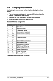
.../2 Compatible Mouse Port 13 8 Numeric Data Processor 14* 9 Primary IDE Channel 15* 10 Secondary IDE Channel * These IRQs are usually available for the expansion card. RS926-E7/RS8 2-17 Assign an IRQ to the tables on the next page. 3. 2.5.2 Configuring an expansion card After installing the expansion card, configure the it by adjusting...
.../2 Compatible Mouse Port 13 8 Numeric Data Processor 14* 9 Primary IDE Channel 15* 10 Secondary IDE Channel * These IRQs are usually available for the expansion card. RS926-E7/RS8 2-17 Assign an IRQ to the tables on the next page. 3. 2.5.2 Configuring an expansion card After installing the expansion card, configure the it by adjusting...
User Guide
Page 41
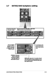
SGPIO_SEL: Set to pin 1-2 to enable onboard C602 SATA SGPIO function (default) or set to support Intel® SCU RAID, LSI RAIO SGPIO function. RS926-E7/RS8 2-19 2.7 SATAII/SAS backplane cabling Connects a 8-pin plug Connects to the Intel® C602 SATA or PIKE SATA from power supply / SAS connectors on the ... of the slim-type optical drive PSGPIO1/2: Connects to BP the SGPIO2/3 connector to pin 2-3 enable optional PIKE SAS RAID, Intel® SCU SGPIO function ASUS RS920-E7/RS8;
SGPIO_SEL: Set to pin 1-2 to enable onboard C602 SATA SGPIO function (default) or set to support Intel® SCU RAID, LSI RAIO SGPIO function. RS926-E7/RS8 2-19 2.7 SATAII/SAS backplane cabling Connects a 8-pin plug Connects to the Intel® C602 SATA or PIKE SATA from power supply / SAS connectors on the ... of the slim-type optical drive PSGPIO1/2: Connects to BP the SGPIO2/3 connector to pin 2-3 enable optional PIKE SAS RAID, Intel® SCU SGPIO function ASUS RS920-E7/RS8;
User Guide
Page 43
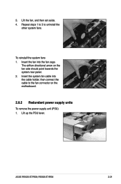
Insert the system fan cable into the fan cage. Lift up the PSU lever. Lift the fan, and then set aside. 4. ASUS RS920-E7/RS8; 3. Repeat steps 1 to 3 to the fan connector on the fan side should point towards the system rear panel. 2. To reinstall the system fans 1. RS926-E7/RS8 2-21 The airflow directional arrow on the motherboard. 2.8.2 Redundant power supply units To remove the power supply unit (PSU) 1. Insert the fan into the cable holder, then connect the cable to uninstall the other system fans.
Insert the system fan cable into the fan cage. Lift up the PSU lever. Lift the fan, and then set aside. 4. ASUS RS920-E7/RS8; 3. Repeat steps 1 to 3 to the fan connector on the fan side should point towards the system rear panel. 2. To reinstall the system fans 1. RS926-E7/RS8 2-21 The airflow directional arrow on the motherboard. 2.8.2 Redundant power supply units To remove the power supply unit (PSU) 1. Insert the fan into the cable holder, then connect the cable to uninstall the other system fans.

User Guide
Page 45
... the total power consumption of the system exceeds 1400W, the maximum output power of the PSUs can reach to install an optional ASUS RAID card on your motherboard. RS926-E7/RS8 2-23 The maximum output power of the system is less than 1400W, the system can be booted using one PSU and the PSU... varies with PSU hot-swap feature disabled, and the system shuts down if any of the SAS RAID card. Output Power (Watt) 1100W 1400W 2.8.3 Installing ASUS PIKE RAID card (optional) Follow the steps below for details.
... the total power consumption of the system exceeds 1400W, the maximum output power of the PSUs can reach to install an optional ASUS RAID card on your motherboard. RS926-E7/RS8 2-23 The maximum output power of the system is less than 1400W, the system can be booted using one PSU and the PSU... varies with PSU hot-swap feature disabled, and the system shuts down if any of the SAS RAID card. Output Power (Watt) 1100W 1400W 2.8.3 Installing ASUS PIKE RAID card (optional) Follow the steps below for details.
User Guide
Page 47
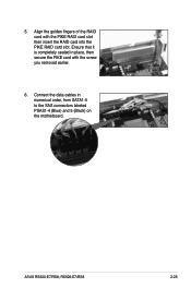
Align the golden fingers of the RAID card with the screw you removed earlier. 6. Ensure that it is completely seated in numerical order, from SATA1-5 to the SAS connectors labeled PSAS1-4 (Blue) and 5 (Black) on the motherboard. 5. ASUS RS920-E7/RS8; RS926-E7/RS8 2-25 Connect the data cables in place, then secure the PIKE card with the PIKE RAID card slot then insert the RAID card into the PIKE RAID card slot.
Align the golden fingers of the RAID card with the screw you removed earlier. 6. Ensure that it is completely seated in numerical order, from SATA1-5 to the SAS connectors labeled PSAS1-4 (Blue) and 5 (Black) on the motherboard. 5. ASUS RS920-E7/RS8; RS926-E7/RS8 2-25 Connect the data cables in place, then secure the PIKE card with the PIKE RAID card slot then insert the RAID card into the PIKE RAID card slot.

User Guide
Page 51
... lip of the rear mounting hole, and then place the front rail hook on the top and the bottom, as shown in the right figure. 2. RS926-E7/RS8 3-3 Secure the front and rear ends of the rail with two thin lips on the bottom thin lip of three square mounting holes with two... rack screws and washers. 5. A 1U space consists of the front mounting hole, as shown in the right figure. 4. ASUS RS920-E7/RS8; Adjust the rack rail to attach the rack rail on the rack where you want to install the rack rail. Repeat step 1 to 4 to fit...
... lip of the rear mounting hole, and then place the front rail hook on the top and the bottom, as shown in the right figure. 2. RS926-E7/RS8 3-3 Secure the front and rear ends of the rail with two thin lips on the bottom thin lip of three square mounting holes with two... rack screws and washers. 5. A 1U space consists of the front mounting hole, as shown in the right figure. 4. ASUS RS920-E7/RS8; Adjust the rack rail to attach the rack rail on the rack where you want to install the rack rail. Repeat step 1 to 4 to fit...
User Guide
Page 53
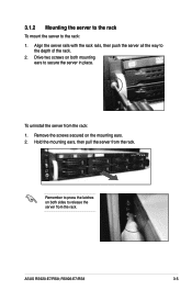
To uninstall the server from the rack. Remember to press the latches on both mounting ears to release the server from the rack. ASUS RS920-E7/RS8; Remove the screws secured on both sides to secure the server in place. 3.1.2 Mounting the server to the rack To mount the server to the depth of the rack. 2. Align the server rails with the rack rails, then push the server all the way to the rack: 1. Drive two screws on the mounting ears. 2. Hold the mounting ears, then pull the server from the rack: 1. RS926-E7/RS8 3-5
To uninstall the server from the rack. Remember to press the latches on both mounting ears to release the server from the rack. ASUS RS920-E7/RS8; Remove the screws secured on both sides to secure the server in place. 3.1.2 Mounting the server to the rack To mount the server to the depth of the rack. 2. Align the server rails with the rack rails, then push the server all the way to the rack: 1. Drive two screws on the mounting ears. 2. Hold the mounting ears, then pull the server from the rack: 1. RS926-E7/RS8 3-5


