User Guide
Page 15
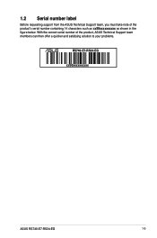
1.2 Serial number label Before requesting support from the ASUS Technical Support team, you must take note of the product, ASUS Technical Support team members can then offer a quicker and satisfying solution to your problems. RS740-E7-RS24-EG xxS0xxxxxxxxxx ASUS RS740-E7-RS24-EG 1-3 With the correct serial number of the product's serial number containing 14 characters such as xxS0xxxxxxxxxx as shown in the figure below.
1.2 Serial number label Before requesting support from the ASUS Technical Support team, you must take note of the product, ASUS Technical Support team members can then offer a quicker and satisfying solution to your problems. RS740-E7-RS24-EG xxS0xxxxxxxxxx ASUS RS740-E7-RS24-EG 1-3 With the correct serial number of the product's serial number containing 14 characters such as xxS0xxxxxxxxxx as shown in the figure below.
User Guide
Page 16
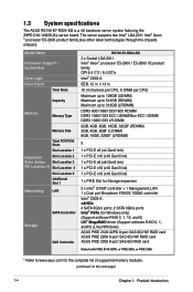
1.3 System specifications The ASUS RS740-E7-RS24-EG is a 4U barebone server system featuring the Z9PE-D16-10G/DUAL server board. x 13 in . Model Name Processor Support / System Bus Core Logic Form Factor ...-E Slots Slot Location 1 Expansion Slot Location 2 Slots (follow Slot Location 3 SSI Location #) Slot Location 4 Slot Location 6 Additional Slot 1 Networking LAN Storage SATA Controller SAS Controller RS740-E7-RS24-EG 2 x Socket LGA 2011 Intel® Xeon® processor E5-2600 / E5-2600 V2 product family QPI 6.4 /7.2 / 8.0 GT/s Intel® C602-A EEB, 12 in . 16 (4 channels...
1.3 System specifications The ASUS RS740-E7-RS24-EG is a 4U barebone server system featuring the Z9PE-D16-10G/DUAL server board. x 13 in . Model Name Processor Support / System Bus Core Logic Form Factor ...-E Slots Slot Location 1 Expansion Slot Location 2 Slots (follow Slot Location 3 SSI Location #) Slot Location 4 Slot Location 6 Additional Slot 1 Networking LAN Storage SATA Controller SAS Controller RS740-E7-RS24-EG 2 x Socket LGA 2011 Intel® Xeon® processor E5-2600 / E5-2600 V2 product family QPI 6.4 /7.2 / 8.0 GT/s Intel® C602-A EEB, 12 in . 16 (4 channels...

User Guide
Page 17
... RS740-E7-RS24-EG 24 x Hot-swap 3.5-inch HDD bays* 2 x Hot-swap 2.5-inch SSD bays (Rear) *Supports 3.5-inch SATA3 or 7200RPM SAS2 HDD. Model Name HDD Bays I Operation temperature: 10°C ~ 35°C / Non operation temperature: -40°C ~ 70°C Non operation humidity: 20% ~ 90% (Non condensing) ** Specifications are subject to change without notice. ASUS RS740-E7-RS24-EG...
... RS740-E7-RS24-EG 24 x Hot-swap 3.5-inch HDD bays* 2 x Hot-swap 2.5-inch SSD bays (Rear) *Supports 3.5-inch SATA3 or 7200RPM SAS2 HDD. Model Name HDD Bays I Operation temperature: 10°C ~ 35°C / Non operation temperature: -40°C ~ 70°C Non operation humidity: 20% ~ 90% (Non condensing) ** Specifications are subject to change without notice. ASUS RS740-E7-RS24-EG...
User Guide
Page 19
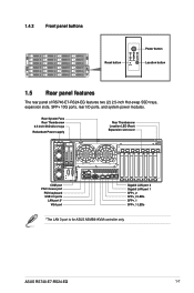
ASUS RS740-E7-RS24-EG 1-7 Rear System Fans Rear Thumbscrew 2.5-inch SSD drive trays Redundant Power supply Rear Thumbscrew Location LED (Rear) Expansion slot cover COM port PS/2 mouse port ... 1 SFP+_2 SFP+_2 LEDs SFP+_1 SFP+_1 LEDs *The LAN 3 port is for ASUS ASMB6-iKVM controller only. 1.4.2 Front panel buttons Power button Reset button 2 1 Location button 2 1 1.5 Rear panel features The rear panel of RS740-E7-RS24-EG features two (2) 2.5-inch Hot-swap SSD trays, expansion slots, SFP+ 10G ports, rear I/O ports, and...
ASUS RS740-E7-RS24-EG 1-7 Rear System Fans Rear Thumbscrew 2.5-inch SSD drive trays Redundant Power supply Rear Thumbscrew Location LED (Rear) Expansion slot cover COM port PS/2 mouse port ... 1 SFP+_2 SFP+_2 LEDs SFP+_1 SFP+_1 LEDs *The LAN 3 port is for ASUS ASMB6-iKVM controller only. 1.4.2 Front panel buttons Power button Reset button 2 1 Location button 2 1 1.5 Rear panel features The rear panel of RS740-E7-RS24-EG features two (2) 2.5-inch Hot-swap SSD trays, expansion slots, SFP+ 10G ports, rear I/O ports, and...
User Guide
Page 21
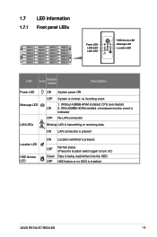
... or receiving data. ON LAN connection is present ON Location switched is normal; Without ASMB6-iKVM installed: CPU over-heated ON 2. no HDD is installed ASUS RS740-E7-RS24-EG 1-9 HDD failure or no incoming event 1. 1.7 LED information 1.7.1 Front panel LEDs 2 1 HDD Access LED Power LED Message LED LAN2 LED Location LED LAN1 LED 2 1 LED...
... or receiving data. ON LAN connection is present ON Location switched is normal; Without ASMB6-iKVM installed: CPU over-heated ON 2. no HDD is installed ASUS RS740-E7-RS24-EG 1-9 HDD failure or no incoming event 1. 1.7 LED information 1.7.1 Front panel LEDs 2 1 HDD Access LED Power LED Message LED LAN2 LED Location LED LAN1 LED 2 1 LED...

User Guide
Page 23
1.7.3 LAN (RJ-45) LEDs SPEED LED ACT/LINK LED ACT/LINK LED Status Description OFF No link GREEN Linked BLINKING Data activity SPEED LED Status Description OFF 10 Mbps connection ORANGE 100 Mbps connection GREEN 1 Gbps connection 1.7.4 SFP+ status LEDs SFP+_2 LEDs SFP+_1 LEDs ACTIVITY LED SPEED LED SFP+ LED Activity/Link LED Status Description OFF No activity BLINKING Data activity Status OFF AMBER GREEN Speed LED Description 1 Gbps connection 10 Gbps connection ASUS RS740-E7-RS24-EG 1-11
1.7.3 LAN (RJ-45) LEDs SPEED LED ACT/LINK LED ACT/LINK LED Status Description OFF No link GREEN Linked BLINKING Data activity SPEED LED Status Description OFF 10 Mbps connection ORANGE 100 Mbps connection GREEN 1 Gbps connection 1.7.4 SFP+ status LEDs SFP+_2 LEDs SFP+_1 LEDs ACTIVITY LED SPEED LED SFP+ LED Activity/Link LED Status Description OFF No activity BLINKING Data activity Status OFF AMBER GREEN Speed LED Description 1 Gbps connection 10 Gbps connection ASUS RS740-E7-RS24-EG 1-11

User Guide
Page 27
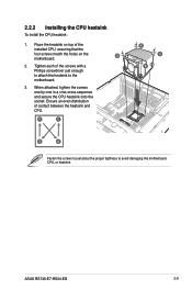
...: 1. Refer to the three (3) holes on the motherboard as indicated in the illustration below. 2 1 A B A C B C 2. 2.1.1 Air Duct The RS740-E7-RS24-EG server system comes with a Phillips screwdriver. Carefully lift the air duct out of the motherboard matching the three (3) screw holes on the air duct to...fan air duct to enable better air flow inside the motherboard while the system is firmly fitted to the motherboard. 2 1 ASUS RS740-E7-RS24-EG 2-3 Remove the chassis cover. Removing the air duct To remove the air duct: 1. Position the air duct on top of the 3 ...
...: 1. Refer to the three (3) holes on the motherboard as indicated in the illustration below. 2 1 A B A C B C 2. 2.1.1 Air Duct The RS740-E7-RS24-EG server system comes with a Phillips screwdriver. Carefully lift the air duct out of the motherboard matching the three (3) screw holes on the air duct to...fan air duct to enable better air flow inside the motherboard while the system is firmly fitted to the motherboard. 2 1 ASUS RS740-E7-RS24-EG 2-3 Remove the chassis cover. Removing the air duct To remove the air duct: 1. Position the air duct on top of the 3 ...

User Guide
Page 29
Load lever 4. Lift the load lever in the direction 5. Slightly lift the load lever in the direction of the arrow (E). B To prevent damage to the right (D) until it is A released from the retention tab. Press the right load lever with your thumb (C), then move it to the left load lever with your thumb (A), then move it to the socket pins, do not remove the PnP cap unless you are installing a CPU. ASUS RS740-E7-RS24-EG E C D 2-5 Press the left (B) until it is released from the retention tab. 3.
Load lever 4. Lift the load lever in the direction 5. Slightly lift the load lever in the direction of the arrow (E). B To prevent damage to the right (D) until it is A released from the retention tab. Press the right load lever with your thumb (C), then move it to the left load lever with your thumb (A), then move it to the socket pins, do not remove the PnP cap unless you are installing a CPU. ASUS RS740-E7-RS24-EG E C D 2-5 Press the left (B) until it is released from the retention tab. 3.

User Guide
Page 31
Insert the right load lever under the retention tab (M). M L ASUS RS740-E7-RS24-EG 2-7 Push down the right load lever (J), ensuring that the edge of the load plate is fastened by the lever (K). K J 10. 9. Push down the left load lever (L), then insert the lever under the retention tab. 11.
Insert the right load lever under the retention tab (M). M L ASUS RS740-E7-RS24-EG 2-7 Push down the right load lever (J), ensuring that the edge of the load plate is fastened by the lever (K). K J 10. 9. Push down the left load lever (L), then insert the lever under the retention tab. 11.
User Guide
Page 33
... match the holes on top of the screws with a Phillips screwdriver just enough to attach the heatsink to avoid damaging the motherboard, CPU, or heatsink. 2 1 ASUS RS740-E7-RS24-EG 2-9 Place the heatsink on the motherboard. When attached, tighten the screws one-by-one in a criss-cross sequence and secure the CPU heatsink onto the...
... match the holes on top of the screws with a Phillips screwdriver just enough to attach the heatsink to avoid damaging the motherboard, CPU, or heatsink. 2 1 ASUS RS740-E7-RS24-EG 2-9 Place the heatsink on the motherboard. When attached, tighten the screws one-by-one in a criss-cross sequence and secure the CPU heatsink onto the...
User Guide
Page 35
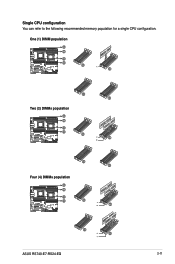
One (1) DIMM population G-H A-B F-E D-C G-H A-B A-B A-B F-E D-C Two (2) DIMMs population G-H A-B A-B F-E D-C D-C G-H A-B A-B F-E D-C D-C Four (4) DIMMs population G-H A-B F-E D-C G-H A-B F-E D-C ASUS RS740-E7-RS24-EG 2-11 A-B Single CPU configuration A-B You can refer to the following recommended memory population for a single CPU configuration.
One (1) DIMM population G-H A-B F-E D-C G-H A-B A-B A-B F-E D-C Two (2) DIMMs population G-H A-B A-B F-E D-C D-C G-H A-B A-B F-E D-C D-C Four (4) DIMMs population G-H A-B F-E D-C G-H A-B F-E D-C ASUS RS740-E7-RS24-EG 2-11 A-B Single CPU configuration A-B You can refer to the following recommended memory population for a single CPU configuration.
User Guide
Page 39
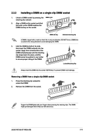
..., then insert the DIMM vertically into the socket. Removing a DIMM from the socket. 2 1 Support the DIMM lightly with your fingers when pressing the retaining clips. ASUS RS740-E7-RS24-EG 2-15 Align a DIMM on the socket such that 1 the notch on the DIMM matches the DIMM slot key on a single clip DIMM socket 1. Unlock a DIMM...
..., then insert the DIMM vertically into the socket. Removing a DIMM from the socket. 2 1 Support the DIMM lightly with your fingers when pressing the retaining clips. ASUS RS740-E7-RS24-EG 2-15 Align a DIMM on the socket such that 1 the notch on the DIMM matches the DIMM slot key on a single clip DIMM socket 1. Unlock a DIMM...

User Guide
Page 41
... HDD drive that the drive tray is seated securely in place. • If the drive is included in place and not properly connected to replace. 2. ASUS RS740-E7-RS24-EG 2-17 When replacing Hard Disk Drives that is not securely seated in a RAID volume: 1. Press the spring lock to release the tray lever and to...
... HDD drive that the drive tray is seated securely in place. • If the drive is included in place and not properly connected to replace. 2. ASUS RS740-E7-RS24-EG 2-17 When replacing Hard Disk Drives that is not securely seated in a RAID volume: 1. Press the spring lock to release the tray lever and to...
User Guide
Page 43
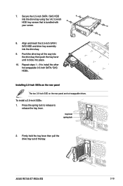
... hot-swappable 3.5-inch SATA / SAS HDDs. Align and insert the 3.5-inch SATA / SAS HDD and drive tray assembly into place. 10. To install a 2.5-inch SSDs: 1. ASUS RS740-E7-RS24-EG 3 2-19 tray lever spring lock 2. Secure the 3.5-inch SATA / SAS HDD into the drive tray using four (4) 3.5-inch HDD tray screws that is bundled with...
... hot-swappable 3.5-inch SATA / SAS HDDs. Align and insert the 3.5-inch SATA / SAS HDD and drive tray assembly into place. 10. To install a 2.5-inch SSDs: 1. ASUS RS740-E7-RS24-EG 3 2-19 tray lever spring lock 2. Secure the 3.5-inch SATA / SAS HDD into the drive tray using four (4) 3.5-inch HDD tray screws that is bundled with...
User Guide
Page 45
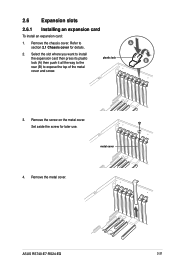
Refer to expose the top of the metal cover and screw. 3. Remove the screw on the metal cover. metal cover 4. ASUS RS740-E7-RS24-EG 2-21 Set aside the screw for details. 2. Remove the metal cover. 2.6 Expansion slots 2.6.1 Installing an expansion card To install an expansion card: 1. Remove the chassis cover. Select the slot where you want to install the expansion card then press its plastic lock (A) then push it all the way to the plastic lock B rear (B) to A section 2.1 Chassis cover for later use.
Refer to expose the top of the metal cover and screw. 3. Remove the screw on the metal cover. metal cover 4. ASUS RS740-E7-RS24-EG 2-21 Set aside the screw for details. 2. Remove the metal cover. 2.6 Expansion slots 2.6.1 Installing an expansion card To install an expansion card: 1. Remove the chassis cover. Select the slot where you want to install the expansion card then press its plastic lock (A) then push it all the way to the plastic lock B rear (B) to A section 2.1 Chassis cover for later use.
User Guide
Page 47
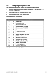
Install the software drivers for ISA or PCI devices. ASUS RS740-E7-RS24-EG 2-23 Assign an IRQ to the following tables. 3. Refer to the card. Turn on BIOS setup. 2. Standard Interrupt assignments IRQ Priority Standard function 0 1 System Timer 1 2 ...
Install the software drivers for ISA or PCI devices. ASUS RS740-E7-RS24-EG 2-23 Assign an IRQ to the following tables. 3. Refer to the card. Turn on BIOS setup. 2. Standard Interrupt assignments IRQ Priority Standard function 0 1 System Timer 1 2 ...
User Guide
Page 49
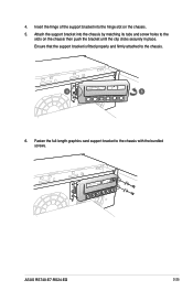
Insert the hinge of the support bracket into the chassis by matching its tabs and screw holes to the slots on the chassis. 5. Ensure that the support bracket is fitted properly and firmly attached to the chassis with the bundled screws. ASUS RS740-E7-RS24-EG 2-25 4. Fasten the full-length graphics card support bracket to the chassis. 4 5 6. Attach the support bracket into the hinge slot on the chassis then push the bracket until the clip clicks securely in place.
Insert the hinge of the support bracket into the chassis by matching its tabs and screw holes to the slots on the chassis. 5. Ensure that the support bracket is fitted properly and firmly attached to the chassis with the bundled screws. ASUS RS740-E7-RS24-EG 2-25 4. Fasten the full-length graphics card support bracket to the chassis. 4 5 6. Attach the support bracket into the hinge slot on the chassis then push the bracket until the clip clicks securely in place.
User Guide
Page 51
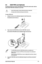
... card slot. • When removing the PIKE RAID card, ensure to slightly pull the metal clip to release it from the card slot. 3. ASUS RS740-E7-RS24-EG 2-27 Install an optional ASUS PIKE RAID card based on the motherboard adjacent to the PIKE RAID card slot in one orientation only. • Ensure that you to...
... card slot. • When removing the PIKE RAID card, ensure to slightly pull the metal clip to release it from the card slot. 3. ASUS RS740-E7-RS24-EG 2-27 Install an optional ASUS PIKE RAID card based on the motherboard adjacent to the PIKE RAID card slot in one orientation only. • Ensure that you to...
User Guide
Page 53
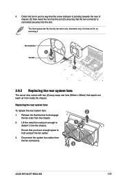
.... Lift the metal fan crate just enough to disengage the fan crate from the chassis. 4. Ensure that expels out warm air from the fan connectors. 2 1 3 ASUS RS740-E7-RS24-EG 2-29
.... Lift the metal fan crate just enough to disengage the fan crate from the chassis. 4. Ensure that expels out warm air from the fan connectors. 2 1 3 ASUS RS740-E7-RS24-EG 2-29
User Guide
Page 55
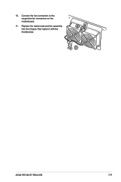
Connect the fan connectors to the respective fan connectors on the motherboard. 11. 10. Replace the metal crate and fan assembly 11 into the chassis then fasten it with the thumbscrew. 10 ASUS RS740-E7-RS24-EG 2-31
Connect the fan connectors to the respective fan connectors on the motherboard. 11. 10. Replace the metal crate and fan assembly 11 into the chassis then fasten it with the thumbscrew. 10 ASUS RS740-E7-RS24-EG 2-31


