RS72xQ-E7_RS12 User Manual
Page 3
...1-6 1.6 Internal features 1-8 1.7 LED information 1-9 1.7.1 Front panel LEDs 1-9 1.7.2 LAN (RJ-45) LEDs 1-10 1.7.3 HDD status LED 1-10 Chapter 2: Hardware setup 2.1 Chassis cover 2-2 2.2 Central Processing Unit (CPU 2-4 2.2.1 Installing the CPU 2-4 2.2.2 Installing the CPU heatsink and airduct 2-9 2.3 System memory 2-11 2.3.1 Overview 2-11 2.3.2 Memory Configurations 2-12 ... 2-19 2.7.1 System fans 2-19 2.7.2 Power supply module 2-20 2.7.3 Installing ASMB6 series management board 2-22 2.7.4 Installing ASUS PIKE Riser Card (optional 2-23 Chapter 3: Installation options iii
...1-6 1.6 Internal features 1-8 1.7 LED information 1-9 1.7.1 Front panel LEDs 1-9 1.7.2 LAN (RJ-45) LEDs 1-10 1.7.3 HDD status LED 1-10 Chapter 2: Hardware setup 2.1 Chassis cover 2-2 2.2 Central Processing Unit (CPU 2-4 2.2.1 Installing the CPU 2-4 2.2.2 Installing the CPU heatsink and airduct 2-9 2.3 System memory 2-11 2.3.1 Overview 2-11 2.3.2 Memory Configurations 2-12 ... 2-19 2.7.1 System fans 2-19 2.7.2 Power supply module 2-20 2.7.3 Installing ASMB6 series management board 2-22 2.7.4 Installing ASUS PIKE Riser Card (optional 2-23 Chapter 3: Installation options iii
RS72xQ-E7_RS12 User Manual
Page 22
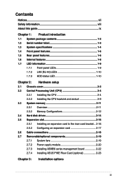
Loosen the six screws on the top and the two sides of the arrow in the following figures. 2. 2.1 Chassis cover Removing the top cover 1. Lift the rear end of the top cover, and follow the direction of the top cover, as shown in the right figure to slide the cover toward the rear panel until it is disengaged from the chassis. 2-2 Chapter 2: Hardware setup
Loosen the six screws on the top and the two sides of the arrow in the following figures. 2. 2.1 Chassis cover Removing the top cover 1. Lift the rear end of the top cover, and follow the direction of the top cover, as shown in the right figure to slide the cover toward the rear panel until it is disengaged from the chassis. 2-2 Chapter 2: Hardware setup

RS72xQ-E7_RS12 User Manual
Page 24
...Contact your left. 2-4 Chapter 2: Hardware setup Locate the CPU socket on the motherboard. ASUS will shoulder the cost of the PnP cap. 2.2.1 Installing the CPU To install a CPU...or if you and the load lever is shipment/transit-related. • Keep the cap after installing the motherboard. ASUS will process Return Merchandise Authorization (RMA) requests only if the motherboard comes with a surface mount LGA2011 socket designed for... comes with the cap on the LGA2011 socket. • The product warranty does not cover damage to the PnP cap/socket contacts/motherboard components.
...Contact your left. 2-4 Chapter 2: Hardware setup Locate the CPU socket on the motherboard. ASUS will shoulder the cost of the PnP cap. 2.2.1 Installing the CPU To install a CPU...or if you and the load lever is shipment/transit-related. • Keep the cap after installing the motherboard. ASUS will process Return Merchandise Authorization (RMA) requests only if the motherboard comes with a surface mount LGA2011 socket designed for... comes with the cap on the LGA2011 socket. • The product warranty does not cover damage to the PnP cap/socket contacts/motherboard components.
RS72xQ-E7_RS12 User Manual
Page 40
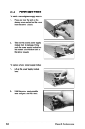
Lift up the power supply module lever. 2. To replace a failed power supply module 1. Firmly push the power supply module into the chassis until the latch locks to the server chassis. 2.7.2 Power supply module To install a second power supply module 1. Take out the second power supply module from the server chassis. 2. Hold the power supply module lever and press the PSU latch. 2-20 Chapter 2: Hardware setup Press and hold the latch on the dummy cover and pull out the cover from its package.
Lift up the power supply module lever. 2. To replace a failed power supply module 1. Firmly push the power supply module into the chassis until the latch locks to the server chassis. 2.7.2 Power supply module To install a second power supply module 1. Take out the second power supply module from the server chassis. 2. Hold the power supply module lever and press the PSU latch. 2-20 Chapter 2: Hardware setup Press and hold the latch on the dummy cover and pull out the cover from its package.
RS72xQ-E7_RS12 User Manual
Page 44
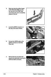
Connect the SGPIO cable to the SGPIO connector on the slot. 7. Locate the SGPIO connector on the side of the PIKE SAS RAID card into the card slot on the PIKE raiser card. 6. Align and insert the golden fingers of the server chassis. 8. Ensure the card is completely seated on the PIKE Riser card. 2. Remove the two (2) screws that secures the metal plate covering the SATA and ISAS connectors. 2-24 Chapter 2: Hardware setup
Connect the SGPIO cable to the SGPIO connector on the slot. 7. Locate the SGPIO connector on the side of the PIKE SAS RAID card into the card slot on the PIKE raiser card. 6. Align and insert the golden fingers of the server chassis. 8. Ensure the card is completely seated on the PIKE Riser card. 2. Remove the two (2) screws that secures the metal plate covering the SATA and ISAS connectors. 2-24 Chapter 2: Hardware setup
RS72xQ-E7_RS12 User Manual
Page 190
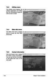
You can also find this information on the inside front cover of this user guide. 7-32 Chapter 7: Driver installation 7.8.3 Utilities menu The Utilities menu displays the software applications and utilities that the motherboard supports. Click an item to install. 7.8.4 Make disk menu The Make disk menu contains items to create the Intel RAID driver disks. 7.8.5 Contact information Click the Contact tab to display the ASUS contact information.
You can also find this information on the inside front cover of this user guide. 7-32 Chapter 7: Driver installation 7.8.3 Utilities menu The Utilities menu displays the software applications and utilities that the motherboard supports. Click an item to install. 7.8.4 Make disk menu The Make disk menu contains items to create the Intel RAID driver disks. 7.8.5 Contact information Click the Contact tab to display the ASUS contact information.