User Guide
Page 4
... 3-2 3.3 Attaching the rack rails 3-3 3.4 Rackmounting the server 3-4 Chapter 4: Motherboard Info 4.1 Motherboard layout 4-2 4.2 Jumpers 4-6 4.3 Internal connectors 4-12 4.4 Internal LEDs 4-20 Chapter 5: BIOS setup 5.1 Managing and updating your BIOS 5-2 5.1.1 AFUDOS utility 5-2 5.1.2 ASUS CrashFree BIOS 3 utility 5-4 5.2 BIOS setup program 5-5 5.2.1 BIOS menu screen 5-6 5.2.2 Menu bar 5-6 5.2.3 Navigation keys 5-6 5.2.4 Menu items 5-7 5.2.5 Sub-menu items 5-7 5.2.6 Configuration fields 5-7 5.2.7 Pop-up window 5-7 5.2.8 Scroll bar 5-7 5.2.9 General...
... 3-2 3.3 Attaching the rack rails 3-3 3.4 Rackmounting the server 3-4 Chapter 4: Motherboard Info 4.1 Motherboard layout 4-2 4.2 Jumpers 4-6 4.3 Internal connectors 4-12 4.4 Internal LEDs 4-20 Chapter 5: BIOS setup 5.1 Managing and updating your BIOS 5-2 5.1.1 AFUDOS utility 5-2 5.1.2 ASUS CrashFree BIOS 3 utility 5-4 5.2 BIOS setup program 5-5 5.2.1 BIOS menu screen 5-6 5.2.2 Menu bar 5-6 5.2.3 Navigation keys 5-6 5.2.4 Menu items 5-7 5.2.5 Sub-menu items 5-7 5.2.6 Configuration fields 5-7 5.2.7 Pop-up window 5-7 5.2.8 Scroll bar 5-7 5.2.9 General...

User Guide
Page 5
... 5.6.4 Security 5-34 5.7 Exit menu 5-36 Chapter 6: RAID configuration 6.1 Setting up RAID 6-2 6.1.1 RAID definitions 6-2 6.1.2 Installing hard disk drives 6-2 6.1.3 RAID controller selection 6-3 6.1.4 Setting the RAID item in BIOS 6-3 6.2 LSI Software RAID Configuration Utility 6-4 6.2.1 Creating a RAID set 6-5 6.2.2 Adding or viewing a RAID configuration 6-11 6.2.3 Initializing the virtual drives 6-12 6.2.4 Rebuilding failed drives 6-16 6.2.5 Checking the...
... 5.6.4 Security 5-34 5.7 Exit menu 5-36 Chapter 6: RAID configuration 6.1 Setting up RAID 6-2 6.1.1 RAID definitions 6-2 6.1.2 Installing hard disk drives 6-2 6.1.3 RAID controller selection 6-3 6.1.4 Setting the RAID item in BIOS 6-3 6.2 LSI Software RAID Configuration Utility 6-4 6.2.1 Creating a RAID set 6-5 6.2.2 Adding or viewing a RAID configuration 6-11 6.2.3 Initializing the virtual drives 6-12 6.2.4 Rebuilding failed drives 6-16 6.2.5 Checking the...

User Guide
Page 6
... Options 6-30 Exiting the Intel® Matrix Storage Manager 6-31 Rebuilding the RAID 6-31 Setting the Boot array in the BIOS Setup Utility 6-33 Chapter 7: Driver installation 7.1 RAID driver installation 7-2 7.1.1 Creating a RAID driver disk 7-2 7.1.2 Installing the... LAN driver installation 7-19 7.4 VGA driver installation 7-22 7.5 Mellanox ConnectX DDR PCI Gen2 Channel Adapter driver installation (For RS702D-E6/PS8; RS704D-E6/PS8 7-24 7.5.1 7.5.2 Windows operating system 7-24 Red Hat® Enterprise Linux OS 7-27 7.6 Management applications and utilities installation 7-...
... Options 6-30 Exiting the Intel® Matrix Storage Manager 6-31 Rebuilding the RAID 6-31 Setting the Boot array in the BIOS Setup Utility 6-33 Chapter 7: Driver installation 7.1 RAID driver installation 7-2 7.1.1 Creating a RAID driver disk 7-2 7.1.2 Installing the... LAN driver installation 7-19 7.4 VGA driver installation 7-22 7.5 Mellanox ConnectX DDR PCI Gen2 Channel Adapter driver installation (For RS702D-E6/PS8; RS704D-E6/PS8 7-24 7.5.1 7.5.2 Windows operating system 7-24 Red Hat® Enterprise Linux OS 7-27 7.6 Management applications and utilities installation 7-...
User Guide
Page 9
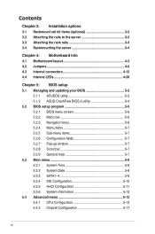
... placed in municipal waste. DO NOT throw the motherboard in municipal waste. This symbol of parts and recycling. Chapter 5: BIOS information This chapter tells how to install the optional components and devices into the barebone server. 4. This product has been designed... jumpers and internal connectors. 5. Chapter 3: Installation options This chapter describes how to change system settings through the BIOS Setup menus and describes the BIOS parameters. 6. Chapter 4: Motherboard information This chapter includes the motherboard layout and brief descriptions of the server, including...
... placed in municipal waste. DO NOT throw the motherboard in municipal waste. This symbol of parts and recycling. Chapter 5: BIOS information This chapter tells how to install the optional components and devices into the barebone server. 4. This product has been designed... jumpers and internal connectors. 5. Chapter 3: Installation options This chapter describes how to change system settings through the BIOS Setup menus and describes the BIOS parameters. 6. Chapter 4: Motherboard information This chapter includes the motherboard layout and brief descriptions of the server, including...
User Guide
Page 32
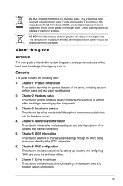
Assign an IRQ to the following tables. 3. See Chapter 5 for information on the system and change the necessary BIOS settings, if any. Programmable Interrupt 4* 12 Communications Port (COM1) 5* 13 -- 6 14 Floppy Disk Controller 7* 15 -- 8 3 System CMOS/Real Time Clock...Data Processor 14* 9 Primary IDE Channel 15* 10 Secondary IDE Channel * These IRQs are usually available for the expansion card. Turn on BIOS setup. 2. Refer to the card. 2.5.2 Configuring an expansion card After installing the expansion card, configure the it by adjusting the software settings....
Assign an IRQ to the following tables. 3. See Chapter 5 for information on the system and change the necessary BIOS settings, if any. Programmable Interrupt 4* 12 Communications Port (COM1) 5* 13 -- 6 14 Floppy Disk Controller 7* 15 -- 8 3 System CMOS/Real Time Clock...Data Processor 14* 9 Primary IDE Channel 15* 10 Secondary IDE Channel * These IRQs are usually available for the expansion card. Turn on BIOS setup. 2. Refer to the card. 2.5.2 Configuring an expansion card After installing the expansion card, configure the it by adjusting the software settings....

User Guide
Page 49
...USB connector (5-1 pin USB3; Force BIOS recovery setting (3-pin RECOVERY1) Page 4-6 4-7 4-8 4-9 4-10 4-11 Internal connectors 1. Clear RTC RAM (CLRTC1) 2. LPC debug card ...connector (14-1 pin LPC1) 5. Power Supply SMBus connectors (6-1 pin JP1, JP2) 8. Standby power LED 2. DDR3 voltage control setting (4-pin LVDDR3_SEL1, LVDDR3_SEL2) 4. BMC header (BMC_FW1) 7. Proprietary power connectors (20-pin PWR1, 20-pin PWR2, 4-pin PWR3) 9. CPU warning LED (ERR_CPU1, ERR_CPU2) Page 4-20 4-20 ASUS RS700D-E6/PS8, RS702D-E6/PS8, RS704D-E6/PS8...
...USB connector (5-1 pin USB3; Force BIOS recovery setting (3-pin RECOVERY1) Page 4-6 4-7 4-8 4-9 4-10 4-11 Internal connectors 1. Clear RTC RAM (CLRTC1) 2. LPC debug card ...connector (14-1 pin LPC1) 5. Power Supply SMBus connectors (6-1 pin JP1, JP2) 8. Standby power LED 2. DDR3 voltage control setting (4-pin LVDDR3_SEL1, LVDDR3_SEL2) 4. BMC header (BMC_FW1) 7. Proprietary power connectors (20-pin PWR1, 20-pin PWR2, 4-pin PWR3) 9. CPU warning LED (ERR_CPU1, ERR_CPU2) Page 4-20 4-20 ASUS RS700D-E6/PS8, RS702D-E6/PS8, RS704D-E6/PS8...
User Guide
Page 50
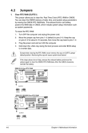
... help, remove the onboard battery and move the cap back to pins 1-2. 3. The onboard button cell battery powers the RAM data in CMOS. Except when clearing the RTC RAM, never remove the cap on pins 2-3 for about 5-10 seconds, then move the jumper again to clear the Real ... Hold down the key during the boot process and enter BIOS setup to pins 2-3. To erase the RTC RAM: 1. After the CMOS clearance, reinstall the battery. 4-6 Chapter 4: Motherboard information Clear RTC RAM (CLRTC1) This jumper allows you to clear the CMOS RTC RAM data. You can clear the CMOS memory of date, time...
... help, remove the onboard battery and move the cap back to pins 1-2. 3. The onboard button cell battery powers the RAM data in CMOS. Except when clearing the RTC RAM, never remove the cap on pins 2-3 for about 5-10 seconds, then move the jumper again to clear the Real ... Hold down the key during the boot process and enter BIOS setup to pins 2-3. To erase the RTC RAM: 1. After the CMOS clearance, reinstall the battery. 4-6 Chapter 4: Motherboard information Clear RTC RAM (CLRTC1) This jumper allows you to clear the CMOS RTC RAM data. You can clear the CMOS memory of date, time...
User Guide
Page 52
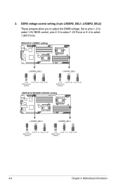
Set to pins 1-2 to select 1.5V BIOS control, pins 2-3 to select 1.2V Force or 3-4 to adjust the DIMM voltage. LVDDR3_SEL2) These jumpers allow you to select 1.35V Force. 4-8 Chapter 4: Motherboard information 3. DDR3 voltage control setting (4-pin LVDDR3_SEL1;
Set to pins 1-2 to select 1.5V BIOS control, pins 2-3 to select 1.2V Force or 3-4 to adjust the DIMM voltage. LVDDR3_SEL2) These jumpers allow you to select 1.35V Force. 4-8 Chapter 4: Motherboard information 3. DDR3 voltage control setting (4-pin LVDDR3_SEL1;

User Guide
Page 55
Insert the USB flash and turn on the system. To update the BIOS: 1. Turn on the system to pins 2-3. 3. ASUS RS700D-E6/PS8, RS702D-E6/PS8, RS704D-E6/PS8 4-11 Prepare a USB flash disk that contains the original or latest BIOS for the motherboard (XXXXXX.ROM) and the AFUDOS.EXE utility. 2. Set the jumper to update the BIOS. 4. Force BIOS recovery setting (3-pin RECOVERY1) This jumper allows you to pins 1-2. 6. Set the jumper back to quickly update or recover the BIOS settings when it becomes corrupted. Shut down the system. 5. 6.
Insert the USB flash and turn on the system. To update the BIOS: 1. Turn on the system to pins 2-3. 3. ASUS RS700D-E6/PS8, RS702D-E6/PS8, RS704D-E6/PS8 4-11 Prepare a USB flash disk that contains the original or latest BIOS for the motherboard (XXXXXX.ROM) and the AFUDOS.EXE utility. 2. Set the jumper to update the BIOS. 4. Force BIOS recovery setting (3-pin RECOVERY1) This jumper allows you to pins 1-2. 6. Set the jumper back to quickly update or recover the BIOS settings when it becomes corrupted. Shut down the system. 5. 6.
User Guide
Page 62
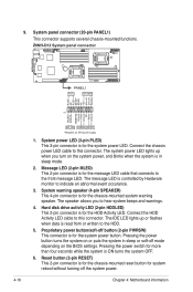
...-mounted system warning speaker. System warning speaker (4-pin SPEAKER) This 4-pin connector is ON turns the system OFF. 6. The speaker allows you turn on the BIOS settings.
...-mounted system warning speaker. System warning speaker (4-pin SPEAKER) This 4-pin connector is ON turns the system OFF. 6. The speaker allows you turn on the BIOS settings.

User Guide
Page 65
Detailed descriptions of the BIOS parameters are also provided. ASUS RS700D-E6/PS8, RS702D-E6/PS8, RS704D-E6/PS8 BIOS setup Chapter 5 This chapter tells how to change the system settings through the BIOS Setup menus.
Detailed descriptions of the BIOS parameters are also provided. ASUS RS700D-E6/PS8, RS702D-E6/PS8, RS704D-E6/PS8 BIOS setup Chapter 5 This chapter tells how to change the system settings through the BIOS Setup menus.

User Guide
Page 66
... during the updating process. A:\>afudos /oOLDBIOS1.rom AMI Firmware Update Utility - Reading flash ..... done Write to copy the current BIOS file that the USB flash drive is any user-assigned filename not more than eight alphanumeric characters for the main filename and three... alphanumeric characters for the extension name. ASUS CrashFree BIOS 3 (To recover the BIOS using a USB flash drive when the BIOS file fails or gets corrupted.) Refer to the bootable USB flash drive. 2. Copy the AFUDOS utility (afudos...
... during the updating process. A:\>afudos /oOLDBIOS1.rom AMI Firmware Update Utility - Reading flash ..... done Write to copy the current BIOS file that the USB flash drive is any user-assigned filename not more than eight alphanumeric characters for the main filename and three... alphanumeric characters for the extension name. ASUS CrashFree BIOS 3 (To recover the BIOS using a USB flash drive when the BIOS file fails or gets corrupted.) Refer to the bootable USB flash drive. 2. Copy the AFUDOS utility (afudos...

User Guide
Page 67
... Utility - done Verifying flash .... You need to the bootable USB flash drive. 3. Erasing flash ...... done Please restart your computer A:\> ASUS RS700D-E6/PS8, RS702D-E6/PS8, RS704D-E6/PS8 5-3 A:\>afudos /iRS702DE6.ROM 4. The utility verifies the file, and then starts updating the BIOS file. done Writing flash ...... 0x0008CC00 (9%) DO NOT shut down or reset the system while updating the...
... Utility - done Verifying flash .... You need to the bootable USB flash drive. 3. Erasing flash ...... done Please restart your computer A:\> ASUS RS700D-E6/PS8, RS702D-E6/PS8, RS704D-E6/PS8 5-3 A:\>afudos /iRS702DE6.ROM 4. The utility verifies the file, and then starts updating the BIOS file. done Writing flash ...... 0x0008CC00 (9%) DO NOT shut down or reset the system while updating the...

User Guide
Page 68
... corrupted during the updating process. The system requires you to enter BIOS Setup to the USB port. 3. DO NOT shut down or reset the system while recovering the BIOS! You can cause system boot failure! 5-4 Chapter 5: BIOS setup 5.1.2 ASUS CrashFree BIOS 3 utility The ASUS CrashFree BIOS 3 utility is an auto recovery tool that allows you to restore...
... corrupted during the updating process. The system requires you to enter BIOS Setup to the USB port. 3. DO NOT shut down or reset the system while recovering the BIOS! You can cause system boot failure! 5-4 Chapter 5: BIOS setup 5.1.2 ASUS CrashFree BIOS 3 utility The ASUS CrashFree BIOS 3 utility is an auto recovery tool that allows you to restore...

User Guide
Page 69
... off and then back on your screen. • Visit the ASUS website at www.asus.com to enter the Setup utility; See section 5.7 Exit Menu. • The BIOS setup screens shown in this motherboard. ASUS RS700D-E6/PS8, RS702D-E6/PS8, RS704D-E6/PS8 5-5 Even if you see on . Do this utility. You... optimum performance. Being a menu-driven program, it as possible. 5.2 BIOS setup program This motherboard supports a programmable firmware chip that the computer can recognize these changes and record them in the CMOS RAM of your computer in the future. The firmware chip on the system ...
... off and then back on your screen. • Visit the ASUS website at www.asus.com to enter the Setup utility; See section 5.7 Exit Menu. • The BIOS setup screens shown in this motherboard. ASUS RS700D-E6/PS8, RS702D-E6/PS8, RS704D-E6/PS8 5-5 Even if you see on . Do this utility. You... optimum performance. Being a menu-driven program, it as possible. 5.2 BIOS setup program This motherboard supports a programmable firmware chip that the computer can recognize these changes and record them in the CMOS RAM of your computer in the future. The firmware chip on the system ...
User Guide
Page 70
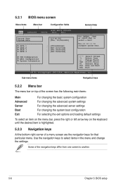
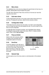
... General Help Save and Exit Exit v02.61 (C)Copyright 1985-2009, American Megatrends, Inc. Use [+] or [-] to select a field. 5.2.1 BIOS menu screen Menu items Menu bar Configuration fields General help Main Advanced BIOS SETUP UTILITY Server Boot Exit System Time [13:44:30] System Date [Thu, 01/08/2009] SATA 1 SATA 2 SATA... of the navigation keys differ from one screen to select items in the menu and change the settings. Use the navigation keys to another. 5-6 Chapter 5: BIOS setup Some of a menu screen are the navigation keys for that particular menu.
... General Help Save and Exit Exit v02.61 (C)Copyright 1985-2009, American Megatrends, Inc. Use [+] or [-] to select a field. 5.2.1 BIOS menu screen Menu items Menu bar Configuration fields General help Main Advanced BIOS SETUP UTILITY Server Boot Exit System Time [13:44:30] System Date [Thu, 01/08/2009] SATA 1 SATA 2 SATA... of the navigation keys differ from one screen to select items in the menu and change the settings. Use the navigation keys to another. 5-6 Chapter 5: BIOS setup Some of a menu screen are the navigation keys for that particular menu.
User Guide
Page 71
... Help Save and Exit Exit v02.61 (C)Copyright 1985-2009, American Megatrends, Inc. You cannot select an item that the item has a sub-menu. ASUS RS700D-E6/PS8, RS702D-E6/PS8, RS704D-E6/PS8 5-7 Advanced BIOS SETUP UTILITY CPU Bridge Chipset Configuration USB Functions [1D2isUaSbBlePdorts] USB Port Configure [82X4USUBSBPoProtrsts] USB 2.0 Controller [E4naUbSlBedP]orts HDA Controller [E6naUbSlBedP]orts SMBUS Controller...
... Help Save and Exit Exit v02.61 (C)Copyright 1985-2009, American Megatrends, Inc. You cannot select an item that the item has a sub-menu. ASUS RS700D-E6/PS8, RS702D-E6/PS8, RS704D-E6/PS8 5-7 Advanced BIOS SETUP UTILITY CPU Bridge Chipset Configuration USB Functions [1D2isUaSbBlePdorts] USB Port Configure [82X4USUBSBPoProtrsts] USB 2.0 Controller [E4naUbSlBedP]orts HDA Controller [E6naUbSlBedP]orts SMBUS Controller...

User Guide
Page 72
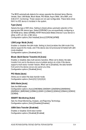
...2009, American Megatrends, Inc. 5.3.1 System Time [xx:xx:xx] Allows you to set the system date. 5.3.3 SATA1-4 The BIOS automatically detects the connected IDE devices. Main BIOS SETUP UTILITY SATA 1 Device :Hard Disk Vendor :ST3160812AS Size :160.0GB LBA Mode :Supported Block Mode:16Sectors PIO Mode :4 ...Mode. Change Option F1 General Help F10 Save and Exit ESC Exit v02.61 (C)Copyright 1985-2009, American Megatrends, Inc. 5-8 Chapter 5: BIOS setup There is not already formatted with LBA Mode disabled. Auto: Enables LBA Mode if the device supports it and the devide is a separate...
...2009, American Megatrends, Inc. 5.3.1 System Time [xx:xx:xx] Allows you to set the system date. 5.3.3 SATA1-4 The BIOS automatically detects the connected IDE devices. Main BIOS SETUP UTILITY SATA 1 Device :Hard Disk Vendor :ST3160812AS Size :160.0GB LBA Mode :Supported Block Mode:16Sectors PIO Mode :4 ...Mode. Change Option F1 General Help F10 Save and Exit ESC Exit v02.61 (C)Copyright 1985-2009, American Megatrends, Inc. 5-8 Chapter 5: BIOS setup There is not already formatted with LBA Mode disabled. Auto: Enables LBA Mode if the device supports it and the devide is a separate...
User Guide
Page 73
... device is installed in the system. Configuration options: [Disabled] [Auto] PIO Mode [Auto] Allows you are not user-configurable. Configuration options: [Disabled] [Enabled] ASUS RS700D-E6/PS8, RS702D-E6/PS8, RS704D-E6/PS8 5-9 The BIOS automatically detects the values opposite the dimmed items (Device, Vendor, Size, LBA Mode, Block Mode, PIO Mode, Async DMA, Ultra DMA, and S.M.A.R.T. Select [CDROM...
... device is installed in the system. Configuration options: [Disabled] [Auto] PIO Mode [Auto] Allows you are not user-configurable. Configuration options: [Disabled] [Enabled] ASUS RS700D-E6/PS8, RS702D-E6/PS8, RS704D-E6/PS8 5-9 The BIOS automatically detects the values opposite the dimmed items (Device, Vendor, Size, LBA Mode, Block Mode, PIO Mode, Async DMA, Ultra DMA, and S.M.A.R.T. Select [CDROM...

User Guide
Page 74
... installed in the system. Configuration options: [0] [5] [10] [15] [20] [25] [30] [35] 5-10 Chapter 5: BIOS setup The AHCI allows the onboard storage driver to enable advanced Serial ATA features that increases storage performance on random workloads by the Southbridge chip.... Hard Disk Write Protect [Disabled] Disables or enables device write protection. Main BIOS SETUP UTILITY IDE Configuration SATA Configuration Configure SATA as [Enhanced] [IDE] Hard Disk Write Protect [Disabled] IDE Detect Time Out ...
... installed in the system. Configuration options: [0] [5] [10] [15] [20] [25] [30] [35] 5-10 Chapter 5: BIOS setup The AHCI allows the onboard storage driver to enable advanced Serial ATA features that increases storage performance on random workloads by the Southbridge chip.... Hard Disk Write Protect [Disabled] Disables or enables device write protection. Main BIOS SETUP UTILITY IDE Configuration SATA Configuration Configure SATA as [Enhanced] [IDE] Hard Disk Write Protect [Disabled] IDE Detect Time Out ...


