User Guide
Page 3
... features 1-5 1.6 Internal features 1-6 1.7 LED information 1-7 1.7.1 Front panel LEDs 1-7 1.7.2 LAN (RJ-45) LEDs 1-7 1.7.3 HDD status LED 1-8 Chapter 2: Hardware setup 2.1 Chassis cover 2-2 2.2 Central Processing Unit (CPU 2-3 2.2.1 Installing the CPU 2-3 2.2.2 Installing the CPU heatsink and airduct 2-6 2.3 System memory 2-7 2.3.1 Overview 2-7 2.3.2 Memory Configurations 2-7 2.3.3 Installing a DIMM 2-9 2.3.4 Removing a DIMM 2-9 2.4 Hard disk drives 2-10 2.5 Expansion slot 2-12 2.5.1 Installing an expansion card...
... features 1-5 1.6 Internal features 1-6 1.7 LED information 1-7 1.7.1 Front panel LEDs 1-7 1.7.2 LAN (RJ-45) LEDs 1-7 1.7.3 HDD status LED 1-8 Chapter 2: Hardware setup 2.1 Chassis cover 2-2 2.2 Central Processing Unit (CPU 2-3 2.2.1 Installing the CPU 2-3 2.2.2 Installing the CPU heatsink and airduct 2-6 2.3 System memory 2-7 2.3.1 Overview 2-7 2.3.2 Memory Configurations 2-7 2.3.3 Installing a DIMM 2-9 2.3.4 Removing a DIMM 2-9 2.4 Hard disk drives 2-10 2.5 Expansion slot 2-12 2.5.1 Installing an expansion card...
User Guide
Page 5
Contents 5.3.4 Storage Configuration 5-11 5.3.5 System Information 5-12 5.4 Advanced menu 5-14 5.4.1 CPU Configuration 5-14 5.4.2 Chipset Configuration 5-16 5.4.3 Onboard Devices Configuration 5-25 5.4.4 USB Configuration 5-26 5.4.5 PCIPnP 5-27 5.5...5-34 5.7.1 Boot Device Priority 5-34 5.7.2 Hard Disk Drives; CDROM Drives 5-34 5.7.3 Boot Settings Configuration 5-35 5.7.4 Security 5-36 5.8 Tools menu 5-38 5.8.1 ASUS EZ Flash 2 5-38 5.9 Exit menu 5-39 Chapter 6: RAID configuration 6.1 Setting up RAID 6-2 6.1.1 RAID definitions 6-2 6.1.2 Installing hard disk drives 6-3 6.1.3 ...
Contents 5.3.4 Storage Configuration 5-11 5.3.5 System Information 5-12 5.4 Advanced menu 5-14 5.4.1 CPU Configuration 5-14 5.4.2 Chipset Configuration 5-16 5.4.3 Onboard Devices Configuration 5-25 5.4.4 USB Configuration 5-26 5.4.5 PCIPnP 5-27 5.5...5-34 5.7.1 Boot Device Priority 5-34 5.7.2 Hard Disk Drives; CDROM Drives 5-34 5.7.3 Boot Settings Configuration 5-35 5.7.4 Security 5-36 5.8 Tools menu 5-38 5.8.1 ASUS EZ Flash 2 5-38 5.9 Exit menu 5-39 Chapter 6: RAID configuration 6.1 Setting up RAID 6-2 6.1.1 RAID definitions 6-2 6.1.2 Installing hard disk drives 6-3 6.1.3 ...
User Guide
Page 12
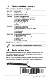
...-R10A) 1 x PCI Riser Card (RE16L-R10) 1 x Front I/O Shield (FPB-AR14) 5 x System Fans (40 x 56mm) 1 x Air Duct 1 x RS500A-E6/PS4 User Guide 1 x ASUS ASWM 2.0 User Guide 1 x RS500A-E6/PS4 Support CD (including ASWM*) 1 x Bag of Screws 1 x AC Power Cable 1 x Friction Rail Kit 2 x CPU Heatsinks (varies by territories) 1 x Slim-type Optical Device 1 x ASMB4-iKVM Remote Management Card 1 x PIKE RAID Card...
...-R10A) 1 x PCI Riser Card (RE16L-R10) 1 x Front I/O Shield (FPB-AR14) 5 x System Fans (40 x 56mm) 1 x Air Duct 1 x RS500A-E6/PS4 User Guide 1 x ASUS ASWM 2.0 User Guide 1 x RS500A-E6/PS4 Support CD (including ASWM*) 1 x Bag of Screws 1 x AC Power Cable 1 x Friction Rail Kit 2 x CPU Heatsinks (varies by territories) 1 x Slim-type Optical Device 1 x ASMB4-iKVM Remote Management Card 1 x PIKE RAID Card...
User Guide
Page 13
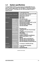
... supports AMD® LGA 1944 Opteron™ 6100 series processors with HyperTransport™ technology, plus other latest technologies through the chipsets onboard. 1.3 System specifications The ASUS RS500A-E6/PS4 is a server featuring the ASUS KGNE-D16 server board.
... supports AMD® LGA 1944 Opteron™ 6100 series processors with HyperTransport™ technology, plus other latest technologies through the chipsets onboard. 1.3 System specifications The ASUS RS500A-E6/PS4 is a server featuring the ASUS KGNE-D16 server board.
User Guide
Page 14
Auxiliary Storage CD / DVD Onboard I/O OS Support Anti-virus Software Software Management Out of Band Solution Remote Management Dimension (HH x WW x DD) Net Weight Kg (CPU, DRAM & HDD not inclu ded) Power Supply Environment 1 x Slim-type Optical Device Bay (Options: No Device / DVD-RW) 3 x RJ-45 ports (One for ASMB4-iKVM) 4 x ...
Auxiliary Storage CD / DVD Onboard I/O OS Support Anti-virus Software Software Management Out of Band Solution Remote Management Dimension (HH x WW x DD) Net Weight Kg (CPU, DRAM & HDD not inclu ded) Power Supply Environment 1 x Slim-type Optical Device Bay (Options: No Device / DVD-RW) 3 x RJ-45 ports (One for ASMB4-iKVM) 4 x ...
User Guide
Page 21
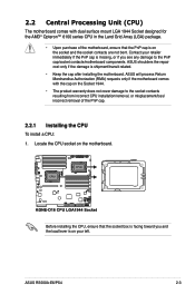
...you and the load lever is on your left. Before installing the CPU, ensure that the PnP cap is on the socket and the socket contacts are not bent. ASUS will process Return Merchandise Authorization (RMA) requests only if the motherboard ...CPU) The motherboard comes with the cap on the motherboard. ASUS shoulders the repair cost only if the damage is facing toward you see any damage to the socket contacts resulting from incorrect CPU installation/removal, or misplacement/loss/ incorrect removal of the PnP cap. 2.2.1 Installing the CPU To install a CPU: 1. ASUS RS500A-E6/PS4...
...you and the load lever is on your left. Before installing the CPU, ensure that the PnP cap is on the socket and the socket contacts are not bent. ASUS will process Return Merchandise Authorization (RMA) requests only if the motherboard ...CPU) The motherboard comes with the cap on the motherboard. ASUS shoulders the repair cost only if the damage is facing toward you see any damage to the socket contacts resulting from incorrect CPU installation/removal, or misplacement/loss/ incorrect removal of the PnP cap. 2.2.1 Installing the CPU To install a CPU: 1. ASUS RS500A-E6/PS4...
User Guide
Page 22
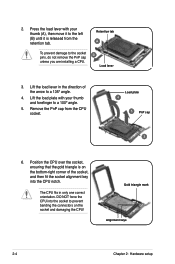
...PnP cap 3 6. 2. Remove the PnP cap from the retention tab. DO NOT force the CPU into the CPU notch. Position the CPU over the socket, ensuring that the gold triangle is released from the CPU socket. Retention tab A To prevent damage to prevent bending the connectors on the bottom‑right...angle. 5. Press the load lever with your thumb (A), then move it to the left (B) until it is on the socket and damaging the CPU! Lift the load lever in only one correct orientation. Gold triangle mark Alignment keys 2-4 Chapter 2: Hardware setup Lift the load plate with your ...
...PnP cap 3 6. 2. Remove the PnP cap from the retention tab. DO NOT force the CPU into the CPU notch. Position the CPU over the socket, ensuring that the gold triangle is released from the CPU socket. Retention tab A To prevent damage to prevent bending the connectors on the bottom‑right...angle. 5. Press the load lever with your thumb (A), then move it to the left (B) until it is on the socket and damaging the CPU! Lift the load lever in only one correct orientation. Gold triangle mark Alignment keys 2-4 Chapter 2: Hardware setup Lift the load plate with your ...
User Guide
Page 23
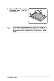
7. If so, skip this step. Close the load plate (A), then push the load lever (B) until it is spread in contact with pre-applied Thermal Interface Material. Some heatsinks come with , ensuring that the heatsink will be in an even thin layer. ASUS RS500A-E6/PS4 2-5 B Apply some Thermal Interface Material to the exposed area of the CPU that it snaps into A the retention tab.
7. If so, skip this step. Close the load plate (A), then push the load lever (B) until it is spread in contact with pre-applied Thermal Interface Material. Some heatsinks come with , ensuring that the heatsink will be in an even thin layer. ASUS RS500A-E6/PS4 2-5 B Apply some Thermal Interface Material to the exposed area of the CPU that it snaps into A the retention tab.
User Guide
Page 24
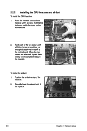
Position the airduct on top of the installed CPU, ensuring that the two fasteners match the holes on top of the heatsink. 2. Carefully lower the airduct until it fits in place. 2-6 Chapter 2: Hardware setup Twist each of the two screws with a Philips (cross) screwdriver just enough to attach the heatsink to completely secure the heatsink. To install the airduct: 1. Place the heatsink on the motherboard. 2. When the two screws are attached, tighten them one by one to the motherboard. 2.2.2 Installing the CPU heatsink and airduct To install the CPU heatsink: 1.
Position the airduct on top of the installed CPU, ensuring that the two fasteners match the holes on top of the heatsink. 2. Carefully lower the airduct until it fits in place. 2-6 Chapter 2: Hardware setup Twist each of the two screws with a Philips (cross) screwdriver just enough to attach the heatsink to completely secure the heatsink. To install the airduct: 1. Place the heatsink on the motherboard. 2. When the two screws are attached, tighten them one by one to the motherboard. 2.2.2 Installing the CPU heatsink and airduct To install the CPU heatsink: 1.
User Guide
Page 53
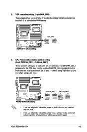
...2-3, the fan you installed may not work and the fan you to enable or disable the onboard VGA controller. The CPUFAN_SEL1 jumper is for the CPU fans control and the CHAFAN_SEL1 jumper is for fan pin selection. VGA controller setting (3-pin VGA_SW1) This jumper allows you installed will not work .... 4-pin fan, the fan control will always run at full speed. Set to pins 1-2 to switch for the front fans and rear fans control. ASUS RS500A-E6/PS4 4-5 CPU Fan and Chassis Fan control setting (3-pin CPUFAN_SEL1, CHAFAN_SEL1) These jumpers allow you to activate the VGA feature. 3. 2.
...2-3, the fan you installed may not work and the fan you to enable or disable the onboard VGA controller. The CPUFAN_SEL1 jumper is for the CPU fans control and the CHAFAN_SEL1 jumper is for fan pin selection. VGA controller setting (3-pin VGA_SW1) This jumper allows you installed will not work .... 4-pin fan, the fan control will always run at full speed. Set to pins 1-2 to switch for the front fans and rear fans control. ASUS RS500A-E6/PS4 4-5 CPU Fan and Chassis Fan control setting (3-pin CPUFAN_SEL1, CHAFAN_SEL1) These jumpers allow you to activate the VGA feature. 3. 2.
User Guide
Page 58
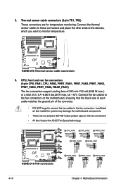
Connect the fan cables to the fan connectors on the fan connectors! • All fans feature the ASUS Fan Speed technology. 4-10 Chapter 4: Motherboard information Connect the thermal sensor cables to these connectors and place the other ends to the devices, ... the ground pin of 3.15 A-6.66 A (53.28 W max.) at +12V. Thermal sensor cable connectors (3-pin TR1, TR2) These connectors are not jumpers! CPU, front and rear fan connectors (4-pin CPU_FAN1, CPU_FAN2, FRNT_FAN1, FRNT_FAN2, FRNT_FAN3, FRNT_FAN4, FRNT_FAN5, REAR_FAN1) The fan connectors support cooling fans of 350 mA-740 mA...
Connect the fan cables to the fan connectors on the fan connectors! • All fans feature the ASUS Fan Speed technology. 4-10 Chapter 4: Motherboard information Connect the thermal sensor cables to these connectors and place the other ends to the devices, ... the ground pin of 3.15 A-6.66 A (53.28 W max.) at +12V. Thermal sensor cable connectors (3-pin TR1, TR2) These connectors are not jumpers! CPU, front and rear fan connectors (4-pin CPU_FAN1, CPU_FAN2, FRNT_FAN1, FRNT_FAN2, FRNT_FAN3, FRNT_FAN4, FRNT_FAN5, REAR_FAN1) The fan connectors support cooling fans of 350 mA-740 mA...
User Guide
Page 75
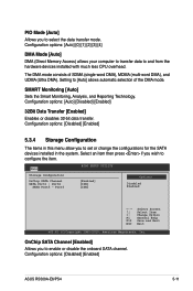
... if you to enable or disable the onboard SATA channel. SMART Monitoring [Auto] Sets the Smart Monitoring, Analysis, and Reporting Technology. Configuration options: [Disabled] [Enabled] ASUS RS500A-E6/PS4 5-11 Main BIOS SETUP UTILITY Storage Configuration OnChip SATA Channel [Enabled] SATA Port1 - OnChip SATA Channel [Enabled] Allows you wish to configure the item. The... options: [Auto] [0] [1] [2] [3] [4] DMA Mode [Auto] DMA (Direct Memory Access) allows your computer to transfer data to and from the hardware devices installed with much less CPU overhead.
... if you to enable or disable the onboard SATA channel. SMART Monitoring [Auto] Sets the Smart Monitoring, Analysis, and Reporting Technology. Configuration options: [Disabled] [Enabled] ASUS RS500A-E6/PS4 5-11 Main BIOS SETUP UTILITY Storage Configuration OnChip SATA Channel [Enabled] SATA Port1 - OnChip SATA Channel [Enabled] Allows you wish to configure the item. The... options: [Auto] [0] [1] [2] [3] [4] DMA Mode [Auto] DMA (Direct Memory Access) allows your computer to transfer data to and from the hardware devices installed with much less CPU overhead.
User Guide
Page 77
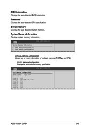
System Memory Displays the auto-detected system memory. Processor Displays the auto-detected CPU specification. CPU1/2 Memory Configuration Displays the auto-detected memory specification. System Memory Information Displays system ...check information of installed memory (8 DIMMs per CPU). BIOS Information Displays the auto-detected BIOS information. Main CPU1 Memory Configuration Node0 Speed Node1 Speed DDR3 1067 N/A DIMM_A1 DIMM_A2 DIMM_B1 DIMM_B2 DIMM_C1 DIMM_C2 DIMM_D1 DIMM_D2 N/A 2048 MB, 2R, 1067 N/A N/A N/A N/A N/A N/A BIOS SETUP UTILITY ASUS RS500A-E6/PS4 5-13
System Memory Displays the auto-detected system memory. Processor Displays the auto-detected CPU specification. CPU1/2 Memory Configuration Displays the auto-detected memory specification. System Memory Information Displays system ...check information of installed memory (8 DIMMs per CPU). BIOS Information Displays the auto-detected BIOS information. Main CPU1 Memory Configuration Node0 Speed Node1 Speed DDR3 1067 N/A DIMM_A1 DIMM_A2 DIMM_B1 DIMM_B2 DIMM_C1 DIMM_C2 DIMM_D1 DIMM_D2 N/A 2048 MB, 2R, 1067 N/A N/A N/A N/A N/A N/A BIOS SETUP UTILITY ASUS RS500A-E6/PS4 5-13
User Guide
Page 78
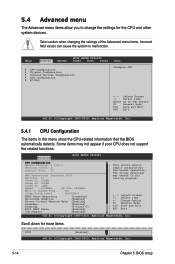
5.4 Advanced menu The Advanced menu items allow you to change the settings for the normal operation. Advanced BIOS SETUP UTILITY CPU Configuration Module Version: 5.1102.1 Physical Count: 2 Logical Count : 12 AMD Opteron(tm) Processor 6172 Revision: D1... 0] [Enabled] [Enabled] This option should remain disabled for the CPU and other system devices. Main Advanced Server BIOS SETUP UTILITY Power Boot Tools CPU Configuration Chipset Configuration Onborad Devices Configuration USB Configuration PCIPnP Exit Configure CPU. ←→ Select Screen ↑↓ Select Item Enter Go...
5.4 Advanced menu The Advanced menu items allow you to change the settings for the normal operation. Advanced BIOS SETUP UTILITY CPU Configuration Module Version: 5.1102.1 Physical Count: 2 Logical Count : 12 AMD Opteron(tm) Processor 6172 Revision: D1... 0] [Enabled] [Enabled] This option should remain disabled for the CPU and other system devices. Main Advanced Server BIOS SETUP UTILITY Power Boot Tools CPU Configuration Chipset Configuration Onborad Devices Configuration USB Configuration PCIPnP Exit Configure CPU. ←→ Select Screen ↑↓ Select Item Enter Go...
User Guide
Page 80
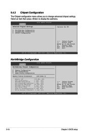
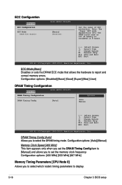
... Megatrends, Inc. 5-16 Chapter 5: BIOS setup NorthBridge Configuration Advanced BIOS SETUP UTILITY NorthBrideg Chipset Configuration Memory Configuration ECC Configuration DRAM Timing Configuration Memroy Timing Parameters [CPU Node 0] Memory CLK :533 MHz, N/A CAS Latency(Tcl) :7 CLK , N/A RAS/CAS Delay(Trcd) :7 CLK , N/A Row Precharge Time(Trp):7 CLK , N/A Min Active RAS(Tras) :20 CLK...
... Megatrends, Inc. 5-16 Chapter 5: BIOS setup NorthBridge Configuration Advanced BIOS SETUP UTILITY NorthBrideg Chipset Configuration Memory Configuration ECC Configuration DRAM Timing Configuration Memroy Timing Parameters [CPU Node 0] Memory CLK :533 MHz, N/A CAS Latency(Tcl) :7 CLK , N/A RAS/CAS Delay(Trcd) :7 CLK , N/A Row Precharge Time(Trp):7 CLK , N/A Min Active RAS(Tras) :20 CLK...
User Guide
Page 82
... F10 Save and Exit ESC Exit v02.61 (C)Copyright 1985-2010, American Megatrends, Inc. Configuration options: [400 MHz] [533 MHz] [667 MHz] Memory Timing Parameters [CPU Node 0] Allows you to set the DRAM Timing Config item to [Manual] and allows you to select which node's timing parameters to display. 5-18 Chapter...
... F10 Save and Exit ESC Exit v02.61 (C)Copyright 1985-2010, American Megatrends, Inc. Configuration options: [400 MHz] [533 MHz] [667 MHz] Memory Timing Parameters [CPU Node 0] Allows you to set the DRAM Timing Config item to [Manual] and allows you to select which node's timing parameters to display. 5-18 Chapter...
User Guide
Page 96
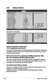
... v02.61 (C)Copyright 1985-2010, American Megatrends, Inc. Select [Ignored] if you to configure the ASUS Smart Fan feature that smartly adjusts the fan speeds for more efficient system operation. CPU Fan1/2; Front Fan1-5 Speed [xxxxRPM] or [Ignored] / [N/A] Rear Fan1 Speed [xxxxRPM] or ...detected temperatures. 5.6.6 Hardware Monitor BIOS SETUP UTILITY Power Hardware Monitor CPU1 Temperature CPU2 Temperature TR1 Temperature TR2 Temperature CPU Fan1 Speed CPU Fan2 Speed Front Fan1 Speed Front Fan2 Speed Front Fan3 Speed Front Fan4 Speed Front Fan5 Speed Rear Fan1...
... v02.61 (C)Copyright 1985-2010, American Megatrends, Inc. Select [Ignored] if you to configure the ASUS Smart Fan feature that smartly adjusts the fan speeds for more efficient system operation. CPU Fan1/2; Front Fan1-5 Speed [xxxxRPM] or [Ignored] / [N/A] Rear Fan1 Speed [xxxxRPM] or ...detected temperatures. 5.6.6 Hardware Monitor BIOS SETUP UTILITY Power Hardware Monitor CPU1 Temperature CPU2 Temperature TR1 Temperature TR2 Temperature CPU Fan1 Speed CPU Fan2 Speed Front Fan1 Speed Front Fan2 Speed Front Fan3 Speed Front Fan4 Speed Front Fan5 Speed Rear Fan1...
