User Guide
Page 3
... 1-7 1.7.1 Front panel LEDs 1-7 1.7.2 LAN (RJ-45) LEDs 1-7 Chapter 2: Hardware setup 2.1 Chassis cover 2-2 2.1.1 Removing the cover 2-2 2.1.2 Installing the cover 2-3 2.2 Motherboard information 2-5 2.3 Central Processing Unit (CPU 2-6 2.3.1 Installing the CPU 2-6 2.3.2 Installing the CPU heatsink 2-8 2.4 System memory 2-10 2.4.1 Overview 2-10 2.4.2 Memory configurations 2-10 2.4.3 Installing a DIMM 2-11 2.4.4 Removing a DIMM 2-11 2.5 Replaceable components 2-12 2.5.1 Installing the chassis fans 2-12...
... 1-7 1.7.1 Front panel LEDs 1-7 1.7.2 LAN (RJ-45) LEDs 1-7 Chapter 2: Hardware setup 2.1 Chassis cover 2-2 2.1.1 Removing the cover 2-2 2.1.2 Installing the cover 2-3 2.2 Motherboard information 2-5 2.3 Central Processing Unit (CPU 2-6 2.3.1 Installing the CPU 2-6 2.3.2 Installing the CPU heatsink 2-8 2.4 System memory 2-10 2.4.1 Overview 2-10 2.4.2 Memory configurations 2-10 2.4.3 Installing a DIMM 2-11 2.4.4 Removing a DIMM 2-11 2.5 Replaceable components 2-12 2.5.1 Installing the chassis fans 2-12...
User Guide
Page 5
Contents 5.3.6 System Information 5-15 5.4 Advanced menu 5-16 5.4.1 USB Configuration 5-16 5.4.2 Remote Access Configuration 5-17 5.4.3 Trusted Computing 5-18 5.4.4 MPS Configuration 5-18 5.4.5 CPU Configuration 5-19 5.4.6 Chipset Configuration 5-20 5.4.7 Onboard Devices Configuration 5-21 5.4.8 PCI PnP 5-22 5.5 Power Configuration 5-24 5.5.1 APM Configuration 5-25 5.5.2 Hardware Monitor 5-26 5.6 Boot menu 5-28 5.6.1 Boot ...
Contents 5.3.6 System Information 5-15 5.4 Advanced menu 5-16 5.4.1 USB Configuration 5-16 5.4.2 Remote Access Configuration 5-17 5.4.3 Trusted Computing 5-18 5.4.4 MPS Configuration 5-18 5.4.5 CPU Configuration 5-19 5.4.6 Chipset Configuration 5-20 5.4.7 Onboard Devices Configuration 5-21 5.4.8 PCI PnP 5-22 5.5 Power Configuration 5-24 5.5.1 APM Configuration 5-25 5.5.2 Hardware Monitor 5-26 5.6 Boot menu 5-28 5.6.1 Boot ...

User Guide
Page 12
... Motherboard Component Accessories Optional Items RS100-E5-PI2 ASUS R09 1U Rackmount Chassis ASUS P5BV-M/RS100-E5 Server Board 1 x 220W 80+ Single Power Supply 2 x SATA Cables 1 x PCI Express x16 Riser Card (x8 link) 1 x Front I/O Board (ASUS FPB-R9) 1 x USB Board (ASUS USB-R9) 2 x System Fans (2 x 40x28) 1 x CPU Heatsink 1 x RS100-E5-PI2 User's Guide 1 x ASUS ASWM 2.0 User's Guide 1 x RS100-E5-PI2 Support CD (including ASWM...
... Motherboard Component Accessories Optional Items RS100-E5-PI2 ASUS R09 1U Rackmount Chassis ASUS P5BV-M/RS100-E5 Server Board 1 x 220W 80+ Single Power Supply 2 x SATA Cables 1 x PCI Express x16 Riser Card (x8 link) 1 x Front I/O Board (ASUS FPB-R9) 1 x USB Board (ASUS USB-R9) 2 x System Fans (2 x 40x28) 1 x CPU Heatsink 1 x RS100-E5-PI2 User's Guide 1 x ASUS ASWM 2.0 User's Guide 1 x RS100-E5-PI2 Support CD (including ASWM...
User Guide
Page 13
...-iKVM) 4 x USB 2.0 ports (Front x 2, Rear x 2) 1 x VGA port 1 x PS/2 keyboard port 1 x PS/2 mouse port (continued on the next page) ASUS RS100-E5-PI2 1-3 Supports software RAID 0 & 1 2 x Internal SATA2 HDD Bays 2 x Broadcom® BCM5721 PCI-E GbE LAN - Supports 10/100/1000 Mbps transfer rates XGI® Volari ...or S will be hot-swappable Networking LAN Graphic VGA Auxiliary Storage FDD / CD / DVD Onboard I/O RS100-E5-PI2 1 x Socket LGA775 Intel® Xeon® 3300/3200/3100/3000 Series CPU FSB 1333/1066/800 Intel® 3200 MCH Intel® ICH7R Smart Fan III √ 4 (Dual...
...-iKVM) 4 x USB 2.0 ports (Front x 2, Rear x 2) 1 x VGA port 1 x PS/2 keyboard port 1 x PS/2 mouse port (continued on the next page) ASUS RS100-E5-PI2 1-3 Supports software RAID 0 & 1 2 x Internal SATA2 HDD Bays 2 x Broadcom® BCM5721 PCI-E GbE LAN - Supports 10/100/1000 Mbps transfer rates XGI® Volari ...or S will be hot-swappable Networking LAN Graphic VGA Auxiliary Storage FDD / CD / DVD Onboard I/O RS100-E5-PI2 1 x Socket LGA775 Intel® Xeon® 3300/3200/3100/3000 Series CPU FSB 1333/1066/800 Intel® 3200 MCH Intel® ICH7R Smart Fan III √ 4 (Dual...
User Guide
Page 14
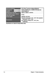
Anti-virus Software Management Hardware Solution Software Dimension (D x W x H) Net Weight Kg (CPU, DRAM & HDD not inclu ded) Power Supply Environment CA® eTrust™ anti-virus software (Optional) SM-Bus/ASMB3-SOL or ASMB3-iKVM (Optional) ASUS ASWM 2.0® 381mm x 430mm x 43.4mm 6.2 Kg 220W 80+ PFC PSU Operation temperature: 10°C ~ 35°C / Non operation temperature: -40°C ~ 70°C Non operation humidity: 20% ~ 90% ( Non- condensing) *Specifications are subject to change without notice. 1-4 Chapter 1: Product introduction
Anti-virus Software Management Hardware Solution Software Dimension (D x W x H) Net Weight Kg (CPU, DRAM & HDD not inclu ded) Power Supply Environment CA® eTrust™ anti-virus software (Optional) SM-Bus/ASMB3-SOL or ASMB3-iKVM (Optional) ASUS ASWM 2.0® 381mm x 430mm x 43.4mm 6.2 Kg 220W 80+ PFC PSU Operation temperature: 10°C ~ 35°C / Non operation temperature: -40°C ~ 70°C Non operation humidity: 20% ~ 90% ( Non- condensing) *Specifications are subject to change without notice. 1-4 Chapter 1: Product introduction

User Guide
Page 24
... purchase of the PnP cap. 2.3.1 Installing the CPU To install a CPU: 1. ASUS shoulders the repair cost only if the damage is shipment/transit-related. • Keep the cap after installing the motherboard. Locate the CPU socket on the motherboard. ® P5BV-M/RS100-E5 P5BV-M/RS100-E5 CPU Socket 775 Before installing the CPU, make sure that the cam box is...
... purchase of the PnP cap. 2.3.1 Installing the CPU To install a CPU: 1. ASUS shoulders the repair cost only if the damage is shipment/transit-related. • Keep the cap after installing the motherboard. Locate the CPU socket on the motherboard. ® P5BV-M/RS100-E5 P5BV-M/RS100-E5 CPU Socket 775 Before installing the CPU, make sure that the cam box is...
User Guide
Page 25
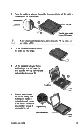
Retention tab A Load lever PnP cap B This side of the socket box should fit into the CPU notch. Lift the load plate with your thumb and forefinger to a 100º angle (A), then push the PnP cap from the retention tab. 2. Load plate 5. ... prevent damage to a 135º angle. 4. Press the load lever with your thumb (A), then move it to remove (B). Alignment key Gold triangle mark ASUS RS100-E5-PI2 A 2-7 Position the CPU over the socket, making sure that the gold triangle is on the bottom-left (B) until it is released from the load B plate window to...
Retention tab A Load lever PnP cap B This side of the socket box should fit into the CPU notch. Lift the load plate with your thumb and forefinger to a 100º angle (A), then push the PnP cap from the retention tab. 2. Load plate 5. ... prevent damage to a 135º angle. 4. Press the load lever with your thumb (A), then move it to remove (B). Alignment key Gold triangle mark ASUS RS100-E5-PI2 A 2-7 Position the CPU over the socket, making sure that the gold triangle is on the bottom-left (B) until it is released from the load B plate window to...
User Guide
Page 26
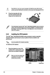
...® 3300/3200/3100/3000 series processors with the heatsink standoffs. Refer to the Appendix for more information on the socket and damaging the CPU! 6. Make sure that the heatsink grill is parallel to ensure optimum thermal condition and performance. Close the load plate (A), then A push ...the load lever (B) until it snaps into the socket to prevent bending the connectors on these CPU features. 2.3.2 Installing the CPU heatsink The Intel® Xeon® 3300/3200/3100/3000 series processors require a specially designed heatsink and fan-duct to the ...
...® 3300/3200/3100/3000 series processors with the heatsink standoffs. Refer to the Appendix for more information on the socket and damaging the CPU! 6. Make sure that the heatsink grill is parallel to ensure optimum thermal condition and performance. Close the load plate (A), then A push ...the load lever (B) until it snaps into the socket to prevent bending the connectors on these CPU features. 2.3.2 Installing the CPU heatsink The Intel® Xeon® 3300/3200/3100/3000 series processors require a specially designed heatsink and fan-duct to the ...
User Guide
Page 31
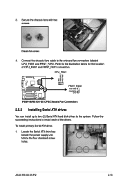
... FANPWR2 FAN PWM ® P5BV-M/RS100-E5 FRNT_FAN1 FAN PWM FANPWR2 GND P5BV-M/RS100-E5 CPU/Chassis Fan Connectors 2.5.2 Installing Serial ATA drives You can install up to two (2) Serial ATA hard disk drives to the onboard fan connectors labeled CPU_FAN1 and FRNT_FAN1. Secure the chassis fans with two screws. ASUS RS100-E5-PI2 2-13 To install primary...
... FANPWR2 FAN PWM ® P5BV-M/RS100-E5 FRNT_FAN1 FAN PWM FANPWR2 GND P5BV-M/RS100-E5 CPU/Chassis Fan Connectors 2.5.2 Installing Serial ATA drives You can install up to two (2) Serial ATA hard disk drives to the onboard fan connectors labeled CPU_FAN1 and FRNT_FAN1. Secure the chassis fans with two screws. ASUS RS100-E5-PI2 2-13 To install primary...
User Guide
Page 49
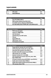
...pin TPM) Page 4-7 4-7 4-7 4-7 4-7 4-7 4-7 4-7 Page 4-8 4-9 4-10 4-11 4-11 4-12 4-12 4-13 4-14 4-15 4-16 ASUS RS100-E5-PI2 4-3 Clear RTC RAM (CLRTC1) 2. Fan mode setting (3-pin CPUFAN_SET1 and CHAFAN_SET1) Page 4-4 4-5 4-5 4-6 Rear panel connectors 1. ICH7R primary IDE connector (40-1 pin PRI_IDE1)... 4. System panel auxiliary connector (20-2 pin AUX_PANEL1) 11. RAID controller selection (3-pin RAID_SEL1) 3. CPU and system fan connectors (4pin CPU_FAN1, FRNT_ FAN1, REAR_FAN1) 8. ATX power connectors (24-pin EATXPWR1, 4-pin ATX12V1) 9. Layout contents...
...pin TPM) Page 4-7 4-7 4-7 4-7 4-7 4-7 4-7 4-7 Page 4-8 4-9 4-10 4-11 4-11 4-12 4-12 4-13 4-14 4-15 4-16 ASUS RS100-E5-PI2 4-3 Clear RTC RAM (CLRTC1) 2. Fan mode setting (3-pin CPUFAN_SET1 and CHAFAN_SET1) Page 4-4 4-5 4-5 4-6 Rear panel connectors 1. ICH7R primary IDE connector (40-1 pin PRI_IDE1)... 4. System panel auxiliary connector (20-2 pin AUX_PANEL1) 11. RAID controller selection (3-pin RAID_SEL1) 3. CPU and system fan connectors (4pin CPU_FAN1, FRNT_ FAN1, REAR_FAN1) 8. ATX power connectors (24-pin EATXPWR1, 4-pin ATX12V1) 9. Layout contents...

User Guide
Page 50
...limitation, AC power off and on CLRTC jumper default position. After the CMOS clearance, reinstall the battery. ® P5BV-M/RS100-E5 CLRTC1 12 23 Normal (Default) P5BV-M/RS100-E5 Clear RTC RAM Clear CMOS • You do not help, remove the onboard battery and move the cap back to pins 2-3. 4.2 Jumpers... in CMOS. Shut down the key during the boot process and enter BIOS setup to overclocking. Clear RTC RAM (CLRTC) This jumper allows you to overclocking, use the C.P.R. (CPU Parameter Recall) feature. Hold down and reboot the system so the BIOS can clear the CMOS memory of...
...limitation, AC power off and on CLRTC jumper default position. After the CMOS clearance, reinstall the battery. ® P5BV-M/RS100-E5 CLRTC1 12 23 Normal (Default) P5BV-M/RS100-E5 Clear RTC RAM Clear CMOS • You do not help, remove the onboard battery and move the cap back to pins 2-3. 4.2 Jumpers... in CMOS. Shut down the key during the boot process and enter BIOS setup to overclocking. Clear RTC RAM (CLRTC) This jumper allows you to overclocking, use the C.P.R. (CPU Parameter Recall) feature. Hold down and reboot the system so the BIOS can clear the CMOS memory of...
User Guide
Page 52
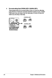
4. Fan mode setting (3-pin CPUFAN_SET1; CHAFAN_SET1) These jumpers allow you to connect either a 3-pin or a 4-pin fan cable plug to the CPU fan or Chasis fan connectors Set these jumpers to pins 1-2 Short PWM mode if you are using a 4-pin fan cable plug, or to pins 2‑3 Short DC mode if you are using a 3-pin plug. ® P5BV-M/RS100-E5 P5BV-M/RS100-E5 Fan Mode Setting CPUFAN_SET1 12 23 PWM Mode (Default) DC Mode CHAFAN_SET1 12 23 PWM Mode (Default) DC Mode 4-6 Chapter 4: Motherboard Information
4. Fan mode setting (3-pin CPUFAN_SET1; CHAFAN_SET1) These jumpers allow you to connect either a 3-pin or a 4-pin fan cable plug to the CPU fan or Chasis fan connectors Set these jumpers to pins 1-2 Short PWM mode if you are using a 4-pin fan cable plug, or to pins 2‑3 Short DC mode if you are using a 3-pin plug. ® P5BV-M/RS100-E5 P5BV-M/RS100-E5 Fan Mode Setting CPUFAN_SET1 12 23 PWM Mode (Default) DC Mode CHAFAN_SET1 12 23 PWM Mode (Default) DC Mode 4-6 Chapter 4: Motherboard Information
User Guide
Page 58
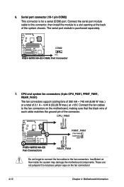
CPU and system fan connectors (4-pin CPU_FAN1, FRNT_FAN1, REAR_FAN1) The fan connectors support cooling fans of 350 mA ~ 740 mA (8.88 W max.) or a total of 2.1 A ~ 4.44 A (... fan connectors on the fan connectors! 4-12 Chapter 4: Motherboard Information Serial port connector (10-1 pin COM2) This connector is purchased separately. ® P5BV-M/RS100-E5 COM2 PIN 1 P5BV-M/RS100-E5 COM2 Port Connector 7. Do not place jumper caps on the motherboard, making sure that the black wire of each cable matches the ground pin...
CPU and system fan connectors (4-pin CPU_FAN1, FRNT_FAN1, REAR_FAN1) The fan connectors support cooling fans of 350 mA ~ 740 mA (8.88 W max.) or a total of 2.1 A ~ 4.44 A (... fan connectors on the fan connectors! 4-12 Chapter 4: Motherboard Information Serial port connector (10-1 pin COM2) This connector is purchased separately. ® P5BV-M/RS100-E5 COM2 PIN 1 P5BV-M/RS100-E5 COM2 Port Connector 7. Do not place jumper caps on the motherboard, making sure that the black wire of each cable matches the ground pin...
User Guide
Page 77
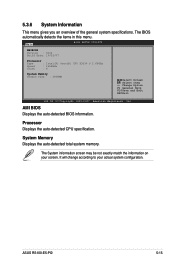
...information screen may be not exactly match the information on your actual system configuration. ASUS RS100-E5-PI2 5-15 System Memory Displays the auto-detected total system memory. Processor Displays the auto-detected CPU specification. 5.3.6 System Information This menu gives you an overview of the general system ...in this menu. Main BIOS SETUP UTILITY AMIBIOS Version : 0104 Build Date: 10/25/07 Processor Type : Intel(R) Xeon(R) CPU X3230 @ 2.66GHz Speed : 2666MHz Count : 4 System Memory Usable Size : 2048MB Select Screen Select Item +- It will change according to your ...
...information screen may be not exactly match the information on your actual system configuration. ASUS RS100-E5-PI2 5-15 System Memory Displays the auto-detected total system memory. Processor Displays the auto-detected CPU specification. 5.3.6 System Information This menu gives you an overview of the general system ...in this menu. Main BIOS SETUP UTILITY AMIBIOS Version : 0104 Build Date: 10/25/07 Processor Type : Intel(R) Xeon(R) CPU X3230 @ 2.66GHz Speed : 2666MHz Count : 4 System Memory Usable Size : 2048MB Select Screen Select Item +- It will change according to your ...
User Guide
Page 78
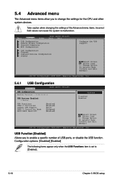
... [Disabled] [Enabled] The following items appear only when the USB Functions item is set to change the settings for the CPU and other system devices. Main Advanced BIOS SETUP UTILITY Power Boot Exit USB Configuration Remote Access Configuration Trusted Computing MPS Configuration... CPU Configuration Chipset Onboard Devices Configuration PCIPnP Configure the USB support. Take caution when changing the settings of USB ports, ...
... [Disabled] [Enabled] The following items appear only when the USB Functions item is set to change the settings for the CPU and other system devices. Main Advanced BIOS SETUP UTILITY Power Boot Exit USB Configuration Remote Access Configuration Trusted Computing MPS Configuration... CPU Configuration Chipset Onboard Devices Configuration PCIPnP Configure the USB support. Take caution when changing the settings of USB ports, ...
User Guide
Page 81
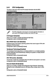
...this item to [Disabled] forces the XD feature flag to always return to zero (0). Configuration options: [Disabled] [Enabled] ASUS RS100-E5-PI2 5-19 5.4.5 CPU Configuration The items in order to enable or disable the "Enhanced Halt State". Change Option F1 General Help F10 Save and...enable or disable the Enhanced Halt State. C1E Support [Enabled] Allows you to cool down. C1E Support Max CPUID Value Limit: Vanderpool Technology CPU TM function: Execute Disable Bit [Enabled] [Disabled] [Enabled] [Enabled] [Enabled] Select Screen Select Item +- Configuration options: [Disabled] [...
...this item to [Disabled] forces the XD feature flag to always return to zero (0). Configuration options: [Disabled] [Enabled] ASUS RS100-E5-PI2 5-19 5.4.5 CPU Configuration The items in order to enable or disable the "Enhanced Halt State". Change Option F1 General Help F10 Save and...enable or disable the Enhanced Halt State. C1E Support [Enabled] Allows you to cool down. C1E Support Max CPUID Value Limit: Vanderpool Technology CPU TM function: Execute Disable Bit [Enabled] [Disabled] [Enabled] [Enabled] [Enabled] Select Screen Select Item +- Configuration options: [Disabled] [...
User Guide
Page 88
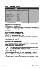
...ASUS Smart Fan feature that the fans operate at a low CPU temperature. Setting a very low ratio may cause a dramatical fan speed drop and trigger a hardware monitor warning message. Select [Ignored] if you set the CPU Smart Fan Control item to [Enabled]. CPU...20%] 5-26 Chapter 5: BIOS setup 5.5.2 Hardware Monitor Power BIOS SETUP UTILITY Hardware Monitor CPU Temperature MB Temperature [43ºC/109ºF] [35ºC/95ºF] CPU_Fan1 Speed CPU Smart Fan Control CPU Fan Ratio CPU Target Temperature FRNT_Fan1 Speed REAR_Fan1 Speed [8544RPM] [Enabled] [Auto] [50ºC] [...
...ASUS Smart Fan feature that the fans operate at a low CPU temperature. Setting a very low ratio may cause a dramatical fan speed drop and trigger a hardware monitor warning message. Select [Ignored] if you set the CPU Smart Fan Control item to [Enabled]. CPU...20%] 5-26 Chapter 5: BIOS setup 5.5.2 Hardware Monitor Power BIOS SETUP UTILITY Hardware Monitor CPU Temperature MB Temperature [43ºC/109ºF] [35ºC/95ºF] CPU_Fan1 Speed CPU Smart Fan Control CPU Fan Ratio CPU Target Temperature FRNT_Fan1 Speed REAR_Fan1 Speed [8544RPM] [Enabled] [Auto] [50ºC] [...
User Guide
Page 89
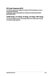
CPU Target Temperature [50ºC] The CPU fan speed will be adjusted to maintain the CPU temperature as low as the selected temperature. ASUS RS100-E5-PI2 5-27 Configuration options: [35ºC] [38ºC] [41ºC] [44ºC] [47ºC] [50ºC] [53ºC] [56ºC] [59ºC] [62ºC] [65ºC] VCORE Voltage, 3.3V Voltage, 5V Voltage, 12V Voltage, VBAT Voltage The onboard hardware monitor automatically detects the voltage outputs through the onboard voltage regulators.
CPU Target Temperature [50ºC] The CPU fan speed will be adjusted to maintain the CPU temperature as low as the selected temperature. ASUS RS100-E5-PI2 5-27 Configuration options: [35ºC] [38ºC] [41ºC] [44ºC] [47ºC] [50ºC] [53ºC] [56ºC] [59ºC] [62ºC] [65ºC] VCORE Voltage, 3.3V Voltage, 5V Voltage, 12V Voltage, VBAT Voltage The onboard hardware monitor automatically detects the voltage outputs through the onboard voltage regulators.

User Guide
Page 145
The Appendix describes the CPU features that the motherboard supports. A Reference information
The Appendix describes the CPU features that the motherboard supports. A Reference information
User Guide
Page 146
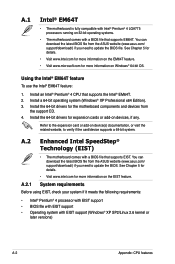
...8226; The motherboard comes with EIST support (Windows® XP SP2/Linux 2.6 kernel or later versions) A-2 Appendix: CPU features You can download the latest BIOS file from the ASUS website (www.asus.com/ support/download/) if you need to verify if the card/device supports a 64-bit system. You can ...download the latest BIOS file from the ASUS website (www.asus.com/ support/download/) if you need to update the BIOS file. See Chapter 5 for details. • Visit www.intel.com for ...
...8226; The motherboard comes with EIST support (Windows® XP SP2/Linux 2.6 kernel or later versions) A-2 Appendix: CPU features You can download the latest BIOS file from the ASUS website (www.asus.com/ support/download/) if you need to verify if the card/device supports a 64-bit system. You can ...download the latest BIOS file from the ASUS website (www.asus.com/ support/download/) if you need to update the BIOS file. See Chapter 5 for details. • Visit www.intel.com for ...


