
User Guide
Page 11
ASUS RS100-E5-PI2 1- It includes sections on front panel and rear panel specifications. Product introduction Chapter 1 This chapter describes the general features of the chassis kit.
ASUS RS100-E5-PI2 1- It includes sections on front panel and rear panel specifications. Product introduction Chapter 1 This chapter describes the general features of the chassis kit.

User Guide
Page 12
... Chassis Motherboard Component Accessories Optional Items RS100-E5-PI2 ASUS R09 1U Rackmount Chassis ASUS P5BV-M/RS100-E5 Server Board 1 x 220W 80+ Single Power Supply 2 x SATA Cables 1 x PCI Express x16 Riser Card (x8 link) 1 x Front I/O Board (ASUS FPB-R9) 1 x USB Board (ASUS USB-R9) 2 x System Fans (2 x 40x28) 1 x CPU Heatsink 1 x RS100-E5-PI2 User's Guide 1 x ASUS ASWM 2.0 User's Guide 1 x RS100-E5-PI2 Support CD (including ASWM*) 1 x Bag...
... Chassis Motherboard Component Accessories Optional Items RS100-E5-PI2 ASUS R09 1U Rackmount Chassis ASUS P5BV-M/RS100-E5 Server Board 1 x 220W 80+ Single Power Supply 2 x SATA Cables 1 x PCI Express x16 Riser Card (x8 link) 1 x Front I/O Board (ASUS FPB-R9) 1 x USB Board (ASUS USB-R9) 2 x System Fans (2 x 40x28) 1 x CPU Heatsink 1 x RS100-E5-PI2 User's Guide 1 x ASUS ASWM 2.0 User's Guide 1 x RS100-E5-PI2 Support CD (including ASWM*) 1 x Bag...
User Guide
Page 13
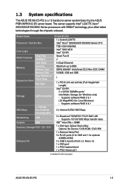
... ports (2 for GbE and 1 for optional ASMB3-iKVM) 4 x USB 2.0 ports (Front x 2, Rear x 2) 1 x VGA port 1 x PS/2 keyboard port 1 x PS/2 mouse port (continued on the next page) ASUS RS100-E5-PI2 1-3 The server supports Intel® LGA775 Xeon® 3300/3200/3100/3000 Series processors with EM64T technology, plus other latest technologies through the chipsets onboard.
... ports (2 for GbE and 1 for optional ASMB3-iKVM) 4 x USB 2.0 ports (Front x 2, Rear x 2) 1 x VGA port 1 x PS/2 keyboard port 1 x PS/2 mouse port (continued on the next page) ASUS RS100-E5-PI2 1-3 The server supports Intel® LGA775 Xeon® 3300/3200/3100/3000 Series processors with EM64T technology, plus other latest technologies through the chipsets onboard.
User Guide
Page 15
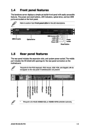
...openings for the rear panel connectors on the rear panel if motherboard is for the LED descriptions. Refer to section 1.6.1 Front panel LEDs for ASUS ASMB3-SOL or ASMB3-iKVM controller card only. Expansion slot LAN port 1 (SOL Shared LAN) LAN port 2 VGA port Serial port iKVM ...with easily accessible features. The ports for the PS/2 keyboard, PS/2 mouse, USB, VGA, and Gigabit LAN do not appear on the motherboard. ASUS RS100-E5-PI2 1-5 USB 2.0 ports Optical drive HDD Access LED LAN2 LED LAN1 LED Power LED Power button Reset button 1.5 Rear panel features The rear panel ...
...openings for the rear panel connectors on the rear panel if motherboard is for the LED descriptions. Refer to section 1.6.1 Front panel LEDs for ASUS ASMB3-SOL or ASMB3-iKVM controller card only. Expansion slot LAN port 1 (SOL Shared LAN) LAN port 2 VGA port Serial port iKVM ...with easily accessible features. The ports for the PS/2 keyboard, PS/2 mouse, USB, VGA, and Gigabit LAN do not appear on the motherboard. ASUS RS100-E5-PI2 1-5 USB 2.0 ports Optical drive HDD Access LED LAN2 LED LAN1 LED Power LED Power button Reset button 1.5 Rear panel features The rear panel ...
User Guide
Page 17
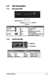
... Status Description OFF No link GREEN Linked BLINKING Data activity SPEED LED Status Description OFF 10 Mbps connection ORANGE 100 Mbps connection GREEN 1 Gbps connection ASUS RS100-E5-PI2 1-7
... Status Description OFF No link GREEN Linked BLINKING Data activity SPEED LED Status Description OFF 10 Mbps connection ORANGE 100 Mbps connection GREEN 1 Gbps connection ASUS RS100-E5-PI2 1-7
User Guide
Page 19
Hardware setup Chapter 2 This chapter lists the hardware setup procedures that you have to perform when installing or removing system components. ASUS RS100-E5-PI2 2-
Hardware setup Chapter 2 This chapter lists the hardware setup procedures that you have to perform when installing or removing system components. ASUS RS100-E5-PI2 2-

User Guide
Page 21
ASUS RS100-E5-PI2 2-3 Slide the cover toward the front until it snaps in place. 2.1.2 Installing the cover 1. Side tabs 2. Position the cover on top of the chassis with the hooks aligned to the side tabs of the chassis.
ASUS RS100-E5-PI2 2-3 Slide the cover toward the front until it snaps in place. 2.1.2 Installing the cover 1. Side tabs 2. Position the cover on top of the chassis with the hooks aligned to the side tabs of the chassis.
User Guide
Page 23
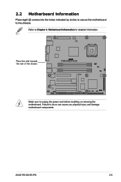
ASUS RS100-E5-PI2 2-5 Place this side towards the rear of the chassis ® P5BV-M/RS100-E5 Make sure to Chapter 4: Motherboard Information for detailed Information. Refer to unplug the power cord before installing or removing the motherboard. 2.2 Motherboard information Place eight (8) screws into the holes indicated by circles to secure the motherboard to do so can cause you physical injury and damage motherboard components. Failure to the chassis.
ASUS RS100-E5-PI2 2-5 Place this side towards the rear of the chassis ® P5BV-M/RS100-E5 Make sure to Chapter 4: Motherboard Information for detailed Information. Refer to unplug the power cord before installing or removing the motherboard. 2.2 Motherboard information Place eight (8) screws into the holes indicated by circles to secure the motherboard to do so can cause you physical injury and damage motherboard components. Failure to the chassis.
User Guide
Page 25
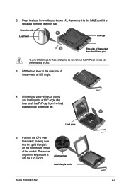
... on the bottom-left corner of the arrow to the socket pins, do not remove the PnP cap unless you . Alignment key Gold triangle mark ASUS RS100-E5-PI2 A 2-7 2.
... on the bottom-left corner of the arrow to the socket pins, do not remove the PnP cap unless you . Alignment key Gold triangle mark ASUS RS100-E5-PI2 A 2-7 2.
User Guide
Page 27
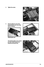
Tighten the screws. 3. Peel the adhesive cover of the heatsink plastic cover and evenly attach to heatsink. ASUS RS100-E5-PI2 2-9 Heatsink plastic cover The heatsink plastic cover ensures the linear airflow between the heatsink and chassis fans. 2.
Tighten the screws. 3. Peel the adhesive cover of the heatsink plastic cover and evenly attach to heatsink. ASUS RS100-E5-PI2 2-9 Heatsink plastic cover The heatsink plastic cover ensures the linear airflow between the heatsink and chassis fans. 2.
User Guide
Page 29
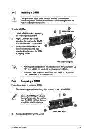
... force a DIMM into the 1 socket until the retaining clips snap back in only one direction. Support the DIMM lightly with extra force. 2 1 1 2. DDR2 DIMM notch ASUS RS100-E5-PI2 2-11 Remove the DIMM from the socket. Align a DIMM on the socket. 3. The DIMM might get damaged when it fits in place and the DIMM...
... force a DIMM into the 1 socket until the retaining clips snap back in only one direction. Support the DIMM lightly with extra force. 2 1 1 2. DDR2 DIMM notch ASUS RS100-E5-PI2 2-11 Remove the DIMM from the socket. Align a DIMM on the socket. 3. The DIMM might get damaged when it fits in place and the DIMM...
User Guide
Page 31
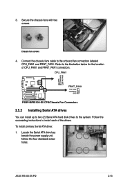
...Notice the four standard screw holes. Refer to install each of CPU_FAN1 and FRNT_FAN1 connectors. CPU_FAN1 GND FANPWR2 FAN PWM ® P5BV-M/RS100-E5 FRNT_FAN1 FAN PWM FANPWR2 GND P5BV-M/RS100-E5 CPU/Chassis Fan Connectors 2.5.2 Installing Serial ATA drives You can install up to two (2) Serial ATA hard disk drives to the onboard... CPU_FAN1 and FRNT_FAN1. Secure the chassis fans with two screws. Connect the chassis fans cable to the system. To install primary Serial ATA drive: 1. ASUS RS100-E5-PI2 2-13 Locate the Serial ATA drive bay beside the power supply unit. 3.
...Notice the four standard screw holes. Refer to install each of CPU_FAN1 and FRNT_FAN1 connectors. CPU_FAN1 GND FANPWR2 FAN PWM ® P5BV-M/RS100-E5 FRNT_FAN1 FAN PWM FANPWR2 GND P5BV-M/RS100-E5 CPU/Chassis Fan Connectors 2.5.2 Installing Serial ATA drives You can install up to two (2) Serial ATA hard disk drives to the onboard... CPU_FAN1 and FRNT_FAN1. Secure the chassis fans with two screws. Connect the chassis fans cable to the system. To install primary Serial ATA drive: 1. ASUS RS100-E5-PI2 2-13 Locate the Serial ATA drive bay beside the power supply unit. 3.
User Guide
Page 33
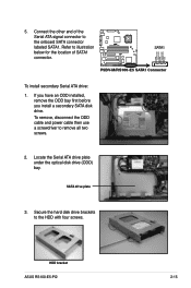
Connect the other end of SATA1 connector. ® P5BV-M/RS100-E5 SATA1 GND RSATA_RXN1 RSATA_RXP1 GND RSATA_TXN1 RSATA_TXP1 GND P5BV-M/RS100-E5 SATA1 Connector To install secondary Serial ATA drive: 1. To remove, disconnect the ODD cable and power cable then use a screwdriver to the ... all two screws. 2. If you have an ODD installed, remove the ODD bay first before you install a secondary SATA disk drive. HDD bracket ASUS RS100-E5-PI2 2-15 SATA drive plate 3. Refer to the HDD with four screws. Locate the Serial ATA drive plate under the optical disk drive (ODD) bay. ...
Connect the other end of SATA1 connector. ® P5BV-M/RS100-E5 SATA1 GND RSATA_RXN1 RSATA_RXP1 GND RSATA_TXN1 RSATA_TXP1 GND P5BV-M/RS100-E5 SATA1 Connector To install secondary Serial ATA drive: 1. To remove, disconnect the ODD cable and power cable then use a screwdriver to the ... all two screws. 2. If you have an ODD installed, remove the ODD bay first before you install a secondary SATA disk drive. HDD bracket ASUS RS100-E5-PI2 2-15 SATA drive plate 3. Refer to the HDD with four screws. Locate the Serial ATA drive plate under the optical disk drive (ODD) bay. ...
User Guide
Page 35
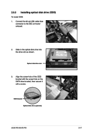
Slide in the optical disk drive into the drive slot as shown. Align the screw hole of the ODD bracket with the screw hole on the SATA drive bracket, then secure it with a screw. Connect the 80-pin IDE cable blue connector to the IDE connector onboard. 2. ODD bracket Optical disk drive (optional) ASUS RS100-E5-PI2 2-17 Optical disk drive slot 3. 2.5.3 Installing optical disk drive (ODD) To install ODD: 1.
Slide in the optical disk drive into the drive slot as shown. Align the screw hole of the ODD bracket with the screw hole on the SATA drive bracket, then secure it with a screw. Connect the 80-pin IDE cable blue connector to the IDE connector onboard. 2. ODD bracket Optical disk drive (optional) ASUS RS100-E5-PI2 2-17 Optical disk drive slot 3. 2.5.3 Installing optical disk drive (ODD) To install ODD: 1.
User Guide
Page 37
ASUS RS100-E5-PI2 2- Installation options Chapter 3 This chapter describes how to install the optional components and devices into the barebone server.
ASUS RS100-E5-PI2 2- Installation options Chapter 3 This chapter describes how to install the optional components and devices into the barebone server.

User Guide
Page 39
Orient the rack ear as shown. ASUS RS100-E5-PI2 3-3 Repeat steps 2 - 4 to attach the other rack ear. 3.1.2 Attaching the rails to the correspoding side of the chassis. Make sure the rail is oriented as shown. 4. Select one rack ear and match the four screw holes to the chassis with three inner rail screws. Secure the rack ear to the screw holes on each front-side of the chassis and secure with four screws. 5. Get one side for installation. 3. Locate the four screw holes on the chassis. Attach the inner rail to the rack To attach the rack rails: 1. 2.
Orient the rack ear as shown. ASUS RS100-E5-PI2 3-3 Repeat steps 2 - 4 to attach the other rack ear. 3.1.2 Attaching the rails to the correspoding side of the chassis. Make sure the rail is oriented as shown. 4. Select one rack ear and match the four screw holes to the chassis with three inner rail screws. Secure the rack ear to the screw holes on each front-side of the chassis and secure with four screws. 5. Get one side for installation. 3. Locate the four screw holes on the chassis. Attach the inner rail to the rack To attach the rack rails: 1. 2.
User Guide
Page 41
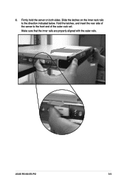
Hold the latches, and insert the rear side of the server to the direction indicated below. Make sure that the inner rails are properly aligned with the outer rails. Firmly hold the server on the inner rack rails to the front end of the outer rack rail. ASUS RS100-E5-PI2 3-5 8. Slide the latches on both sides.
Hold the latches, and insert the rear side of the server to the direction indicated below. Make sure that the inner rails are properly aligned with the outer rails. Firmly hold the server on the inner rack rails to the front end of the outer rack rail. ASUS RS100-E5-PI2 3-5 8. Slide the latches on both sides.

User Guide
Page 43
.... 5. Get one long rack ear and match the six screw holes to support the server system in a rack cabinet. Orient the rack ear as shown. 4. ASUS RS100-E5-PI2 3-7 Locate the six screw holes on the chassis. 3.2 Rackmount bracket kit (Optional) The rackmount bracket kit provides a convenient and economical way to install the server...
.... 5. Get one long rack ear and match the six screw holes to support the server system in a rack cabinet. Orient the rack ear as shown. 4. ASUS RS100-E5-PI2 3-7 Locate the six screw holes on the chassis. 3.2 Rackmount bracket kit (Optional) The rackmount bracket kit provides a convenient and economical way to install the server...

User Guide
Page 45
3.3 Front panel cover kit (Optional) The front panel cover kit provides a convenient way to the chassis with four screws. 4. ASUS RS100-E5-PI2 3-9 Prepare the bundled pair of front panel connectors and a set of twelve (12) screws. 2. Secure the rack ear to protect and decorate the front server panel. 1. Secure the front panel connector to attach the other rack ear. Repeat steps 2 - 3 to the rack ear. 3.
3.3 Front panel cover kit (Optional) The front panel cover kit provides a convenient way to the chassis with four screws. 4. ASUS RS100-E5-PI2 3-9 Prepare the bundled pair of front panel connectors and a set of twelve (12) screws. 2. Secure the rack ear to protect and decorate the front server panel. 1. Secure the front panel connector to attach the other rack ear. Repeat steps 2 - 3 to the rack ear. 3.

User Guide
Page 47
Motherboard Info Chapter 4 This chapter gives inforamtion about the motherboard that comes with the server. ASUS RS100-E5-PI2 4-1 This chapter includes the motherboard layout, jumper settings, and connector locations.
Motherboard Info Chapter 4 This chapter gives inforamtion about the motherboard that comes with the server. ASUS RS100-E5-PI2 4-1 This chapter includes the motherboard layout, jumper settings, and connector locations.