MAXIMUS IX HERO USER S MANUAL ENGLISH
Page 3
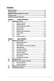
Contents Safety information...vi About this guide...vii MAXIMUS IX HERO specifications summary ix Package contents...xiv Installation tools and components xv Chapter 1: Product Introduction 1.1 Motherboard... 2.1 Building your PC system 2-1 2.1.1 Motherboard installation 2-1 2.1.2 CPU installation 2-3 2.1.3 CPU heatsink and fan assembly installation 2-5 2.1.4 DIMM installation 2-7 2.1.5 ATX power connection 2-8 2.1.6 SATA device connection 2-8 2.1.7 Front I/O connector 2-9 2.1.8 Expansion card installation 2-10 2.1.9 M.2 installation 2-11 2.1.10 3D printing part...
Contents Safety information...vi About this guide...vii MAXIMUS IX HERO specifications summary ix Package contents...xiv Installation tools and components xv Chapter 1: Product Introduction 1.1 Motherboard... 2.1 Building your PC system 2-1 2.1.1 Motherboard installation 2-1 2.1.2 CPU installation 2-3 2.1.3 CPU heatsink and fan assembly installation 2-5 2.1.4 DIMM installation 2-7 2.1.5 ATX power connection 2-8 2.1.6 SATA device connection 2-8 2.1.7 Front I/O connector 2-9 2.1.8 Expansion card installation 2-10 2.1.9 M.2 installation 2-11 2.1.10 3D printing part...

MAXIMUS IX HERO USER S MANUAL ENGLISH
Page 13
... Device LED [YELLOW GREEN] - xiii Q-Connector - ASUS EZ Flash 3 - Q-DIMM Drivers ROG GameFirst IV ROG RAMDisk ROG RamCache II ROG CPU-Z ROG Mem TweakIt Overwolf ROG Keybot II Kaspersky® Anti-Virus Daemon Tools Software ASUS WebStorage ASUS Utilities Windows® 10 64-bit Windows® 8.1... Processors ATX Form Factor, 12"x 9.6" (30.5cm x 24.4cm) Specifications are subject to change without notice. Disk Unlocker ASUS EZ DIY - USB BIOS Flashback - Q-Code - MAXIMUS IX HERO specifications summary Special Features Software Operating System Support Form Factor ASUS Dual...
... Device LED [YELLOW GREEN] - xiii Q-Connector - ASUS EZ Flash 3 - Q-DIMM Drivers ROG GameFirst IV ROG RAMDisk ROG RamCache II ROG CPU-Z ROG Mem TweakIt Overwolf ROG Keybot II Kaspersky® Anti-Virus Daemon Tools Software ASUS WebStorage ASUS Utilities Windows® 10 64-bit Windows® 8.1... Processors ATX Form Factor, 12"x 9.6" (30.5cm x 24.4cm) Specifications are subject to change without notice. Disk Unlocker ASUS EZ DIY - USB BIOS Flashback - Q-Code - MAXIMUS IX HERO specifications summary Special Features Software Operating System Support Form Factor ASUS Dual...

MAXIMUS IX HERO USER S MANUAL ENGLISH
Page 17
...; Unplug the power cord from the wall socket before you install or remove any component, ensure that the ATX power supply is switched off or the power cord is detached from the power supply. ASUS MAXIMUS IX HERO 1-1 Chapter 1 Chapter 1: Product Introduction Product Introduction 1 1.1 Motherboard overview 1.1.1 Before you proceed Take note of the following precautions...
...; Unplug the power cord from the wall socket before you install or remove any component, ensure that the ATX power supply is switched off or the power cord is detached from the power supply. ASUS MAXIMUS IX HERO 1-1 Chapter 1 Chapter 1: Product Introduction Product Introduction 1 1.1 Motherboard overview 1.1.1 Before you proceed Take note of the following precautions...
MAXIMUS IX HERO USER S MANUAL ENGLISH
Page 19
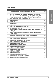
Q_Code LED 7. MemOK! SATA6G_34; USB 2.0 connector (10-1 pin USB1314) 16. ROG Extension connector (18-1 pin ROG_EXT) 17. Safe Boot button (SAFE_BOOT) 23. Power-on button (START) 25. Thunderbolt header (5-pin TB_HEADER) 26...ATX power connectors (24-pin EATXPWR; 8-pin EATX12V) 2. Intel® Z270 Serial ATA 6 Gb/s connectors (7-pin SATA6G_12; Thermal sensor connector (2-pin T_SENSOR) 15. LED connectors (5-pin RGB_LED_STRIP2) Page 1-25 1-4 1-24 1-28 1-5 1-13 1-10 2-12 1-21 1-29 1-20 1-31 1-26 1-27 1-22 1-27 1-21 1-30 1-19 1-12 1-11 1-11 1-9 1-9 1-30 1-23 1-29 ASUS MAXIMUS IX HERO...
Q_Code LED 7. MemOK! SATA6G_34; USB 2.0 connector (10-1 pin USB1314) 16. ROG Extension connector (18-1 pin ROG_EXT) 17. Safe Boot button (SAFE_BOOT) 23. Power-on button (START) 25. Thunderbolt header (5-pin TB_HEADER) 26...ATX power connectors (24-pin EATXPWR; 8-pin EATX12V) 2. Intel® Z270 Serial ATA 6 Gb/s connectors (7-pin SATA6G_12; Thermal sensor connector (2-pin T_SENSOR) 15. LED connectors (5-pin RGB_LED_STRIP2) Page 1-25 1-4 1-24 1-28 1-5 1-13 1-10 2-12 1-21 1-29 1-20 1-31 1-26 1-27 1-22 1-27 1-21 1-30 1-19 1-12 1-11 1-11 1-9 1-9 1-30 1-23 1-29 ASUS MAXIMUS IX HERO...

MAXIMUS IX HERO USER S MANUAL ENGLISH
Page 41
.... • We recommend that complies with more high-end PCIe x16 cards, use a PSU with a higher power output when configuring a system with ATX 12 V Specification 2.0 (or later version) and provides a minimum power of 350 W. • Do not forget to use two or more power-...; If you use a PSU with 1000W power or above to fit these connectors in only one orientation. ATX power connectors (24-pin EATXPWR; 8-pin EATX12V) These connectors are designed to ensure the system stability. The power supply plugs are for ATX power supply plugs. ASUS MAXIMUS IX HERO 1-25 Chapter 1 7.
.... • We recommend that complies with more high-end PCIe x16 cards, use a PSU with a higher power output when configuring a system with ATX 12 V Specification 2.0 (or later version) and provides a minimum power of 350 W. • Do not forget to use two or more power-...; If you use a PSU with 1000W power or above to fit these connectors in only one orientation. ATX power connectors (24-pin EATXPWR; 8-pin EATX12V) These connectors are designed to ensure the system stability. The power supply plugs are for ATX power supply plugs. ASUS MAXIMUS IX HERO 1-25 Chapter 1 7.

MAXIMUS IX HERO USER S MANUAL ENGLISH
Page 42
... the BIOS settings. The system power LED lights up or flashes when data is read from or written to hear system beeps and warnings. • ATX power button/soft-off the system power. 1-26 Chapter 1: Product Introduction System panel connectors (10-1 pin F_PANEL; 4-pin SPEAKER) These connectors supports several chassis-mounted...
... the BIOS settings. The system power LED lights up or flashes when data is read from or written to hear system beeps and warnings. • ATX power button/soft-off the system power. 1-26 Chapter 1: Product Introduction System panel connectors (10-1 pin F_PANEL; 4-pin SPEAKER) These connectors supports several chassis-mounted...

MAXIMUS IX HERO USER S MANUAL ENGLISH
Page 44
AURA RGB headers (4-pin RGB_HEADER1-2) These connectors are for RGB LED strips. Before you install or remove any component, ensure that the ATX power supply is switched off or the power cord is purchased separately. 1-28 Chapter 1: Product Introduction Failure to do so may cause severe damage to ...
AURA RGB headers (4-pin RGB_HEADER1-2) These connectors are for RGB LED strips. Before you install or remove any component, ensure that the ATX power supply is switched off or the power cord is purchased separately. 1-28 Chapter 1: Product Introduction Failure to do so may cause severe damage to ...

MAXIMUS IX HERO USER S MANUAL ENGLISH
Page 56
2.1.5 ATX power connection Chapter 2 Ensure to connect the 8-pin power plug. 2.1.6 SATA device connection OR 2-8 Chapter 2: Basic Installation
2.1.5 ATX power connection Chapter 2 Ensure to connect the 8-pin power plug. 2.1.6 SATA device connection OR 2-8 Chapter 2: Basic Installation

MAXIMUS IX HERO USER S MANUAL ENGLISH
Page 66
Connect the power cord to the power connector at the back of the BIOS setting. 2-18 Chapter 2: Basic Installation External SCSI devices (starting with ATX power supplies, the system LED lights up or change from the time you turned on the chain) c. Check the jumper settings and connections or call ... let the system enter the soft-off . 3. For systems with the last device on the power, the system may light up when you press the ATX power button. Turn on the devices in Chapter 3. 2.5 Turning off the computer While the system is equipped with the "green" standards or if it has...
Connect the power cord to the power connector at the back of the BIOS setting. 2-18 Chapter 2: Basic Installation External SCSI devices (starting with ATX power supplies, the system LED lights up or change from the time you turned on the chain) c. Check the jumper settings and connections or call ... let the system enter the soft-off . 3. For systems with the last device on the power, the system may light up when you press the ATX power button. Turn on the devices in Chapter 3. 2.5 Turning off the computer While the system is equipped with the "green" standards or if it has...

