User Manual
Page 3
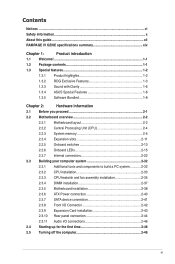
...guide...xii RAMPAGE IV GENE specifications summary xiv Chapter 1: Product introduction 1.1 Welcome!...1-1 1.2 Package contents 1-1 1.3 Special features 1-2 1.3.1 Product highlights 1-2 1.3.2 ROG Exclusive Features 1-3 1.3.3 Sound with Clarity 1-6 1.3.4 ASUS Special Features 1-6 1.3.5 Software Bundled 1-8 Chapter 2: Hardware information 2.1 Before you proceed 2-1 2.2 Motherboard overview 2-2 2.2.1 Motherboard layout 2-2 2.2.2 Central Processing Unit (CPU 2-4 2.2.3 System memory 2-5 2.2.4 Expansion slots 2-11 2.2.5 Onboard switches 2-13 2.2.6 Onboard LEDs 2-15...
...guide...xii RAMPAGE IV GENE specifications summary xiv Chapter 1: Product introduction 1.1 Welcome!...1-1 1.2 Package contents 1-1 1.3 Special features 1-2 1.3.1 Product highlights 1-2 1.3.2 ROG Exclusive Features 1-3 1.3.3 Sound with Clarity 1-6 1.3.4 ASUS Special Features 1-6 1.3.5 Software Bundled 1-8 Chapter 2: Hardware information 2.1 Before you proceed 2-1 2.2 Motherboard overview 2-2 2.2.1 Motherboard layout 2-2 2.2.2 Central Processing Unit (CPU 2-4 2.2.3 System memory 2-5 2.2.4 Expansion slots 2-11 2.2.5 Onboard switches 2-13 2.2.6 Onboard LEDs 2-15...

User Manual
Page 16
RAMPAGE IV GENE specifications summary ASUS Special Features Back I/O Ports Internal I /O 1 x External SATA port 1 x USB 3.0 connector (red) supports additional 2 USB 3.0 ports 2 x USB 2.0 connectors support additional 4 USB 2.0 ports 4 x SATA 6Gb/s connectors (red) 3 x SATA 3Gb/s connectors (black) Debug LED 5 x Fan connectors: - 2 x CPU - 3 x Chassis 11 x Probelt measurement points 1 x SPDIF_out connector 1 x 24 pin ATX power connector 1 x 8-pin ATX 12V power connector...
RAMPAGE IV GENE specifications summary ASUS Special Features Back I/O Ports Internal I /O 1 x External SATA port 1 x USB 3.0 connector (red) supports additional 2 USB 3.0 ports 2 x USB 2.0 connectors support additional 4 USB 2.0 ports 4 x SATA 6Gb/s connectors (red) 3 x SATA 3Gb/s connectors (black) Debug LED 5 x Fan connectors: - 2 x CPU - 3 x Chassis 11 x Probelt measurement points 1 x SPDIF_out connector 1 x 24 pin ATX power connector 1 x 8-pin ATX 12V power connector...

User Manual
Page 29
...-1 pin USB3_34) 8. USB1112) 13. Debug LEDs 6. Go Button 15. ASMedia Serial ATA 6Gb/s connectors (7-pin SATA6G_E1/E2 [red]) 11. ATX power connector (24-pin EATXPWR) 7. Intel X79 Serial ATA 6Gb/s connectors (7-pin SATA6G_1/2 [red]) 10. LGA2011 CPU socket 5. System panel connector (20-8 pin PANEL) 12. CPU, chassis and power fan connectors (4-pin... audio connector (10-1 pin AAFP) Page 2-28 2-5 2-29 2-4 2-17 2-29 2-25 2-23 2-22 2-24 2-29 2-26 2-16 2-14 2-13 2-13 2-27 2-31 Chapter 2 ROG RAMPAGE IV GENE 2-3 Layout contents Connectors/Jumpers/Slots 1.
...-1 pin USB3_34) 8. USB1112) 13. Debug LEDs 6. Go Button 15. ASMedia Serial ATA 6Gb/s connectors (7-pin SATA6G_E1/E2 [red]) 11. ATX power connector (24-pin EATXPWR) 7. Intel X79 Serial ATA 6Gb/s connectors (7-pin SATA6G_1/2 [red]) 10. LGA2011 CPU socket 5. System panel connector (20-8 pin PANEL) 12. CPU, chassis and power fan connectors (4-pin... audio connector (10-1 pin AAFP) Page 2-28 2-5 2-29 2-4 2-17 2-29 2-25 2-23 2-22 2-24 2-29 2-26 2-16 2-14 2-13 2-13 2-27 2-31 Chapter 2 ROG RAMPAGE IV GENE 2-3 Layout contents Connectors/Jumpers/Slots 1.

User Manual
Page 42
Q LED Q LEDs check key components (CPU, DRAM, VGA card, and booting devices) in OS. 3. If an error is found , the corresponding LED will continue lighting until the problem is enabled before POST. This user-friendly design provides an intuitional way to locate the root problem within a second. 2. Lighting: Indicates that MemOK! Chapter 2 2-16 Chapter 2: Hardware information GO LED Blinking: Indicates that the system loads the preset profile (GO_Button file) for temporary overclocking when in sequence during motherboard booting process. is solved.
Q LED Q LEDs check key components (CPU, DRAM, VGA card, and booting devices) in OS. 3. If an error is found , the corresponding LED will continue lighting until the problem is enabled before POST. This user-friendly design provides an intuitional way to locate the root problem within a second. 2. Lighting: Indicates that MemOK! Chapter 2 2-16 Chapter 2: Hardware information GO LED Blinking: Indicates that the system loads the preset profile (GO_Button file) for temporary overclocking when in sequence during motherboard booting process. is solved.


