
User Guide
Page 1
Motherboard PVL-D Series PVL-D/SCSI PVL-D/1U
Motherboard PVL-D Series PVL-D/SCSI PVL-D/1U

User Guide
Page 3
Contents Notices vii Safety information viii About this guide ix Typography x PVL-D specifications summary xi Chapter 1: Product introduction 1.1 Welcome 1-1 1.2 Package contents 1-1 1.3 Special features 1-2 1.3.1 Product highlights 1-2 1.3.2 Innovative ASUS features 1-4 Chapter 2: Hardware information 2.1 Before you proceed 2-1 2.2 Motherboard ...18 2.5.4 PCI/PCI-X slots (For PVL-D/SCSI model only) ....... 2-19 2.5.5 ZCR socket (For PVL-D/SCSI model only 2-19 2.5.6 PCI Express x8 slot 2-20 (For PVL-D/SCSI model only) 2.5.7 Mini-PCI socket (For PVL-D/1U model only) ......... 2-20 ...
Contents Notices vii Safety information viii About this guide ix Typography x PVL-D specifications summary xi Chapter 1: Product introduction 1.1 Welcome 1-1 1.2 Package contents 1-1 1.3 Special features 1-2 1.3.1 Product highlights 1-2 1.3.2 Innovative ASUS features 1-4 Chapter 2: Hardware information 2.1 Before you proceed 2-1 2.2 Motherboard ...18 2.5.4 PCI/PCI-X slots (For PVL-D/SCSI model only) ....... 2-19 2.5.5 ZCR socket (For PVL-D/SCSI model only 2-19 2.5.6 PCI Express x8 slot 2-20 (For PVL-D/SCSI model only) 2.5.7 Mini-PCI socket (For PVL-D/1U model only) ......... 2-20 ...

User Guide
Page 5
... configuration 5-24 5.2.7 Selecting the boot drive from a RAID set 5-25 5.2.8 Enabling the WriteCache 5-26 5.3 Global Array Manager 5-26 5.4 Adaptec SCSISelect(TM) Utility 5-27 (PVL-D/SCSI model only) 5.4.1 Configuring the SCSI controller 5-28 5.4.2 Enabling the HostRAID controller 5-28 5.4.3 Creating a RAID 0 set (Stripe 5-29 5.4.4 Creating a RAID 1 set (Mirror 5-33 5.4.5 Creating a RAID 10 set (Stripe+Mirror...
... configuration 5-24 5.2.7 Selecting the boot drive from a RAID set 5-25 5.2.8 Enabling the WriteCache 5-26 5.3 Global Array Manager 5-26 5.4 Adaptec SCSISelect(TM) Utility 5-27 (PVL-D/SCSI model only) 5.4.1 Configuring the SCSI controller 5-28 5.4.2 Enabling the HostRAID controller 5-28 5.4.3 Creating a RAID 0 set (Stripe 5-29 5.4.4 Creating a RAID 1 set (Mirror 5-33 5.4.5 Creating a RAID 10 set (Stripe+Mirror...

User Guide
Page 6
... and utilities installation 6-15 6.4.1 Running the support CD 6-15 6.4.2 Drivers menu 6-15 6.4.3 Management Software menu 6-16 6.4.4 Utilities menu 6-16 6.4.5 Contact information 6-16 Appendix: Block diagrams A.1 PVL-D/SCSI block diagram A-1 A.2 PVL-D/1U block diagram A-2 vi
... and utilities installation 6-15 6.4.1 Running the support CD 6-15 6.4.2 Drivers menu 6-15 6.4.3 Management Software menu 6-16 6.4.4 Utilities menu 6-16 6.4.5 Contact information 6-16 Appendix: Block diagrams A.1 PVL-D/SCSI block diagram A-1 A.2 PVL-D/1U block diagram A-2 vi
User Guide
Page 11
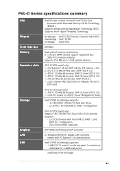
...MHz Dual-channel memory architecture 8 x 240-pin DIMM sockets support registered ECC DDR2-400 memory modules Supports 256 MB up to 16 GB system memory (PVL-D/SCSI model only) 1 x PCI Express™ x8 slot 98P (x8 link, PCI Express 1.0a) 2 x PCI-X 133 MHz/64-bit slots 184P...1 x mini-PCI socket for ASUS® Server Management Board Intel® ICH5R Southbridge supports: - 4 x Ultra DMA 100/66/33 hard disk drives - 2 x SATA-150 with RAID 0, RAID 1 configuration (PVL-D/SCSI model only) Adaptec® AIC-7902W PCI-X Dual U320 SCSI controller supports: - 2 x SCSI channels with PCI Express 1.0a ...
...MHz Dual-channel memory architecture 8 x 240-pin DIMM sockets support registered ECC DDR2-400 memory modules Supports 256 MB up to 16 GB system memory (PVL-D/SCSI model only) 1 x PCI Express™ x8 slot 98P (x8 link, PCI Express 1.0a) 2 x PCI-X 133 MHz/64-bit slots 184P...1 x mini-PCI socket for ASUS® Server Management Board Intel® ICH5R Southbridge supports: - 4 x Ultra DMA 100/66/33 hard disk drives - 2 x SATA-150 with RAID 0, RAID 1 configuration (PVL-D/SCSI model only) Adaptec® AIC-7902W PCI-X Dual U320 SCSI controller supports: - 2 x SCSI channels with PCI Express 1.0a ...

User Guide
Page 12
... Requirement Form Factor Support CD contents ASUS Smart Fan Control ASUS CrashFree BIOS 2 ASUS MyLogo2 AMI BIOS, 8 Mb FWH, Green, PnP, DMI2.0a, ACPI 2.0a SMBIOS 2.3, WfM2.0 1 x PS/2 keyboard port (purple) 1 x PS/2 mouse port (green) 2 x USB 2.0 ports 1 x Serial port 1 x VGA port 2 x LAN (RJ-45) ports 1 x Parallel port (PVL-D/SCSI model only) 1 x Floppy disk drive connector...
... Requirement Form Factor Support CD contents ASUS Smart Fan Control ASUS CrashFree BIOS 2 ASUS MyLogo2 AMI BIOS, 8 Mb FWH, Green, PnP, DMI2.0a, ACPI 2.0a SMBIOS 2.3, WfM2.0 1 x PS/2 keyboard port (purple) 1 x PS/2 mouse port (green) 2 x USB 2.0 ports 1 x Serial port 1 x VGA port 2 x LAN (RJ-45) ports 1 x Parallel port (PVL-D/SCSI model only) 1 x Floppy disk drive connector...

User Guide
Page 15
...it , check the items in -1 floppy disk drive cable Accessories Application CDs Documentation 2 x CEK springs (for buying an ASUS® PVL-D Series motherboard! Thank you start installing the motherboard, and hardware devices on it another standout in the long line of...above items is damaged or missing, contact your motherboard package for the following items. Motherboard ASUS PVL-D Series motherboard Cables 2 x Serial ATA signal cables 1 x Serial ATA power cable (dual-plug) 2 x SCSI Ultra320 cables (PVL-D/CSI model only) 80-conductor IDE cable 3-in your package with the list below. ...
...it , check the items in -1 floppy disk drive cable Accessories Application CDs Documentation 2 x CEK springs (for buying an ASUS® PVL-D Series motherboard! Thank you start installing the motherboard, and hardware devices on it another standout in the long line of...above items is damaged or missing, contact your motherboard package for the following items. Motherboard ASUS PVL-D Series motherboard Cables 2 x Serial ATA signal cables 1 x Serial ATA power cable (dual-plug) 2 x SCSI Ultra320 cables (PVL-D/CSI model only) 80-conductor IDE cable 3-in your package with the list below. ...

User Guide
Page 17
... between devices and allows higher clockspeeds by the Intel® ICH5R. The ZCR capability provides a cost-effective high-performance and added reliability. ASUS PVL-D Series 1-3 See page 2-28 for details. See page 2-19 for details. USB 2.0 is software compatible with a ZCR socket for... your networking needs. Zero-Channel RAID (ZCR) solution (PVL-D/SCSI model only) The motherboard comes with existing PCI or PCI-X specifications. The onboard Broadcom® BCM5721 Gigabit LAN controllers use the PCI...
... between devices and allows higher clockspeeds by the Intel® ICH5R. The ZCR capability provides a cost-effective high-performance and added reliability. ASUS PVL-D Series 1-3 See page 2-28 for details. See page 2-19 for details. USB 2.0 is software compatible with a ZCR socket for... your networking needs. Zero-Channel RAID (ZCR) solution (PVL-D/SCSI model only) The motherboard comes with existing PCI or PCI-X specifications. The onboard Broadcom® BCM5721 Gigabit LAN controllers use the PCI...
User Guide
Page 22
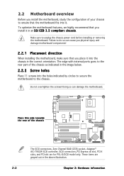
...do so can damage the motherboard. The edge with external ports goes to the rear part of the chassis The SCSI connectors, Zero Channel RAID (ZCR) socket, Adaptec® AIC-7902W SCSI controller, SCSI connectors, PCI Express x8 slot, PCI-X slots, and PCI slot are grayed out in the above illustration. 2-2... recommend that you install it . Failure to unplug the chassis power cord before installing or removing the motherboard. These items are for PVL-D/SCSI model only. PVL-D Series ® Place this side towards the rear of the chassis as indicated in the correct orientation.
...do so can damage the motherboard. The edge with external ports goes to the rear part of the chassis The SCSI connectors, Zero Channel RAID (ZCR) socket, Adaptec® AIC-7902W SCSI controller, SCSI connectors, PCI Express x8 slot, PCI-X slots, and PCI slot are grayed out in the above illustration. 2-2... recommend that you install it . Failure to unplug the chassis power cord before installing or removing the motherboard. These items are for PVL-D/SCSI model only. PVL-D Series ® Place this side towards the rear of the chassis as indicated in the correct orientation.

User Guide
Page 28
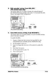
..., USBPW34) 4. Gigabit LAN controller setting (3-pin LAN2_EN1) 8. DDR2 DIMM sockets 3. Gigabit LAN controller setting (3-pin LAN1_EN1) 7. Clear RTC RAM (CLRTC1) 2. Parallel port (for PVL-D/SCSI model only) 3. Serial (COM1) port 5. SCSI controller setting (3-pin SCSI_EN1) 9. Gigabit LAN (RJ-45) ports 7. Keyboard power (3-pin KBPWR1) 5. PS/2 keyboard port (purple) Page 2-10 2-14 2-19 2-19...
..., USBPW34) 4. Gigabit LAN controller setting (3-pin LAN2_EN1) 8. DDR2 DIMM sockets 3. Gigabit LAN controller setting (3-pin LAN1_EN1) 7. Clear RTC RAM (CLRTC1) 2. Parallel port (for PVL-D/SCSI model only) 3. Serial (COM1) port 5. SCSI controller setting (3-pin SCSI_EN1) 9. Gigabit LAN (RJ-45) ports 7. Keyboard power (3-pin KBPWR1) 5. PS/2 keyboard port (purple) Page 2-10 2-14 2-19 2-19...
User Guide
Page 39
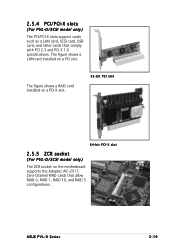
ASUS PVL-D Series 2-19 The figure shows a RAID card installed on a PCI-X slot. 32-bit PCI slot 64-bit PCI-X slot 2.5.5 ZCR socket (For PVL-D/SCSI model only) The ZCR socket on a PCI slot. The figure shows a LAN card installed on the motherboard supports the Adaptec AIC-2015 Zero-Channel RAID cards that comply with PCI 2.3 and PCI-X 1.0 specifications. 2.5.4 PCI/PCI-X slots (For PVL-D/SCSI model only) The PCI/PCI-X slots support cards such as a LAN card, SCSI card, USB card, and other cards that allow RAID 0, RAID 1, RAID 10, and RAID 5 configurations.
ASUS PVL-D Series 2-19 The figure shows a RAID card installed on a PCI-X slot. 32-bit PCI slot 64-bit PCI-X slot 2.5.5 ZCR socket (For PVL-D/SCSI model only) The ZCR socket on a PCI slot. The figure shows a LAN card installed on the motherboard supports the Adaptec AIC-2015 Zero-Channel RAID cards that comply with PCI 2.3 and PCI-X 1.0 specifications. 2.5.4 PCI/PCI-X slots (For PVL-D/SCSI model only) The PCI/PCI-X slots support cards such as a LAN card, SCSI card, USB card, and other cards that allow RAID 0, RAID 1, RAID 10, and RAID 5 configurations.
User Guide
Page 40
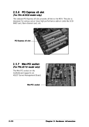
PCI Express x8 slot 2.5.7 Mini-PCI socket (For PVL-D/1U model only) The Mini-PCI socket on cards like SCSI RAID card, fiber-channel card, etc. This slot is designed for various server class high performance add-on the motherboard supports an ASUS® Server Management Board. Mini-PCI socket 2-20 Chapter 2: Hardware information 2.5.6 PCI Express x8 slot (For PVL-D/SCSI model only) The onboard PCI Express x8 slot provides x8 link to the MCH.
PCI Express x8 slot 2.5.7 Mini-PCI socket (For PVL-D/1U model only) The Mini-PCI socket on cards like SCSI RAID card, fiber-channel card, etc. This slot is designed for various server class high performance add-on the motherboard supports an ASUS® Server Management Board. Mini-PCI socket 2-20 Chapter 2: Hardware information 2.5.6 PCI Express x8 slot (For PVL-D/SCSI model only) The onboard PCI Express x8 slot provides x8 link to the MCH.
User Guide
Page 41
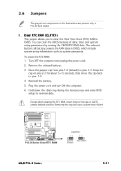
... Time Clock (RTC) RAM in CMOS. Plug the power cord and turn ON the computer. 6. PVL-D Series ® PVL-D Series Clear RTC RAM CLRTC1 21 32 Normal Clear CMOS (Default) ASUS PVL-D Series 2-21 Keep the cap on CLRTC jumper default position. Clear RTC RAM (CLRTC1) This jumper... allows you to pins 1-2. 4. The onboard button cell battery powers the RAM data in PVL-D/SCSI model. 1. 2.6 Jumpers The grayed out components in...
... Time Clock (RTC) RAM in CMOS. Plug the power cord and turn ON the computer. 6. PVL-D Series ® PVL-D Series Clear RTC RAM CLRTC1 21 32 Normal Clear CMOS (Default) ASUS PVL-D Series 2-21 Keep the cap on CLRTC jumper default position. Clear RTC RAM (CLRTC1) This jumper... allows you to pins 1-2. 4. The onboard button cell battery powers the RAM data in PVL-D/SCSI model. 1. 2.6 Jumpers The grayed out components in...
User Guide
Page 45
... you to pins 1-2. 6. Force BIOS recovery setting (3-pin RECOVERY1) This jumper allows you to activate the SCSI feature, and support RAID configurations. PVL-D Series ® RECOVERY1 12 23 Normal BIOS Recovery (Default) PVL-D Series BIOS recovery setting ASUS PVL-D Series 2-25 Set the jumper back to quickly update or recover the BIOS settings when it...
... you to pins 1-2. 6. Force BIOS recovery setting (3-pin RECOVERY1) This jumper allows you to activate the SCSI feature, and support RAID configurations. PVL-D Series ® RECOVERY1 12 23 Normal BIOS Recovery (Default) PVL-D Series BIOS recovery setting ASUS PVL-D Series 2-25 Set the jumper back to quickly update or recover the BIOS settings when it...

User Guide
Page 46
... is for the LAN port LED indications. L A N ( R J - 4 5 ) p o r t s . These two 4-pin Universal Serial Bus (USB) ports are available for a VGA monitor or other devices. (present in PVL-D/SCSI model only) 3 . These ports allow Gigabit connection to the table below for a PS/2 keyboard. 2-26 Chapter 2: Hardware information This 9-pin communication port is for connecting...
... is for the LAN port LED indications. L A N ( R J - 4 5 ) p o r t s . These two 4-pin Universal Serial Bus (USB) ports are available for a VGA monitor or other devices. (present in PVL-D/SCSI model only) 3 . These ports allow Gigabit connection to the table below for a PS/2 keyboard. 2-26 Chapter 2: Hardware information This 9-pin communication port is for connecting...
User Guide
Page 49
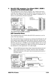
...PVL-D/SCSI Onboard SCSI connectors SCSI Connection Notes This motherboard has two 68-Pin Ultra320 SCSI connectors; Mixing SCSI devices on the same channel decreases performance of the two channels. one for each of SCSI standard (e.g. When an SE device is attached, the bus defaults to 15 devices) PVL-D/SCSI SCSI connection example 68-pin Female Terminator ASUS PVL-D Series 2-29 Connect SCSI... devices as specified by Ultra320 standards. With Ultra320 devices, the SCSI bus...
...PVL-D/SCSI Onboard SCSI connectors SCSI Connection Notes This motherboard has two 68-Pin Ultra320 SCSI connectors; Mixing SCSI devices on the same channel decreases performance of the two channels. one for each of SCSI standard (e.g. When an SE device is attached, the bus defaults to 15 devices) PVL-D/SCSI SCSI connection example 68-pin Female Terminator ASUS PVL-D Series 2-29 Connect SCSI... devices as specified by Ultra320 standards. With Ultra320 devices, the SCSI bus...
User Guide
Page 50
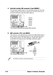
... ® NC GND USB PortB(+) USB PortB(-) Power PVL-D Series USB connector 1 USB34 The USB port module is for USB 2.0 ports. The read or write activities of any device connected to the SCSI connectors or the SATA connectors cause this connector, then install the module to a slot opening at the back of... module cable to this LED to light up to the hard disk activity LED. This USB connector complies with USB 2.0 specification that supports up . HDLED1 1 PVL-D Series SCSI/SATA card activity LED connector 6. PVL-D Series ® SCSI_ACTLED+ SCSI_ACTLEDSCSI_ACTLEDSCSI_ACTLED+ 5 .
... ® NC GND USB PortB(+) USB PortB(-) Power PVL-D Series USB connector 1 USB34 The USB port module is for USB 2.0 ports. The read or write activities of any device connected to the SCSI connectors or the SATA connectors cause this connector, then install the module to a slot opening at the back of... module cable to this LED to light up to the hard disk activity LED. This USB connector complies with USB 2.0 specification that supports up . HDLED1 1 PVL-D Series SCSI/SATA card activity LED connector 6. PVL-D Series ® SCSI_ACTLED+ SCSI_ACTLEDSCSI_ACTLEDSCSI_ACTLED+ 5 .

User Guide
Page 59
... light up or switch between orange and green after the system LED turns on the screen. Follow the instructions in the following order: a. ASUS PVL-D Series 3-1 After making all switches are running, the BIOS beeps (see anything within 30 seconds from the time you press the ATX power...it has a "power standby" feature, the monitor LED may have failed a power-on the chain) c. At power on the devices in Chapter 4. External SCSI devices (starting with a surge protector. 5. 3.1 Starting up for assistance. Be sure that is equipped with the last device on test. Turn on , ...
... light up or switch between orange and green after the system LED turns on the screen. Follow the instructions in the following order: a. ASUS PVL-D Series 3-1 After making all switches are running, the BIOS beeps (see anything within 30 seconds from the time you press the ATX power...it has a "power standby" feature, the monitor LED may have failed a power-on the chain) c. At power on the devices in Chapter 4. External SCSI devices (starting with a surge protector. 5. 3.1 Starting up for assistance. Be sure that is equipped with the last device on test. Turn on , ...
User Guide
Page 65
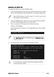
... 2. I 8 0 2 3 A 0 . r o m for the motherboard. Do not turn off power during flash BIOS Reading file ....... ASUS PVL-D Series 4-3 Save the BIOS file to the bootable floppy disk you created earlier. 3. The utility verifies the file and starts updating the BIOS. ...done Advance Check ...... r o m for PVL-D/SCSI model, and I 8 0 2 1 A 0 . Copy the AFUDOS utility (afudos.exe) from the motherboard support CD to a bootable floppy disk. Erasing flash ...... Version 1.19(ASUS V2.07(03.11.24BB)) Copyright (C) 2002 American Megatrends, Inc. ...
... 2. I 8 0 2 3 A 0 . r o m for the motherboard. Do not turn off power during flash BIOS Reading file ....... ASUS PVL-D Series 4-3 Save the BIOS file to the bootable floppy disk you created earlier. 3. The utility verifies the file and starts updating the BIOS. ...done Advance Check ...... r o m for PVL-D/SCSI model, and I 8 0 2 1 A 0 . Copy the AFUDOS utility (afudos.exe) from the motherboard support CD to a bootable floppy disk. Erasing flash ...... Version 1.19(ASUS V2.07(03.11.24BB)) Copyright (C) 2002 American Megatrends, Inc. ...
User Guide
Page 67
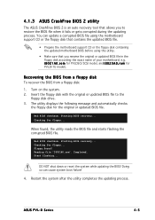
... the BIOS! r o m for PVLDSCI/SCSI model, and I 8 0 2 1 A 0 . Insert the floppy disk with the original or updated BIOS file to restore the BIOS file when it fails or gets corrupted during the updating process. Checking for floppy... When found ! Starting BIOS recovery... ASUS PVL-D Series 4-5 4.1.3 ASUS CrashFree BIOS 2 utility The ASUS CrashFree BIOS 2 is an auto...
... the BIOS! r o m for PVLDSCI/SCSI model, and I 8 0 2 1 A 0 . Insert the floppy disk with the original or updated BIOS file to restore the BIOS file when it fails or gets corrupted during the updating process. Checking for floppy... When found ! Starting BIOS recovery... ASUS PVL-D Series 4-5 4.1.3 ASUS CrashFree BIOS 2 utility The ASUS CrashFree BIOS 2 is an auto...