
User Guide
Page 3
... guide ix Typography x PVL-D specifications summary xi Chapter 1: Product introduction 1.1 Welcome 1-1 1.2 Package contents 1-1 1.3 Special features 1-2 1.3.1 Product highlights 1-2 1.3.2 Innovative ASUS features 1-4 Chapter 2: ...memory 2-14 2.4.1 Overview 2-14 2.4.2 Memory configurations 2-14 2.4.3 Installing a DIMM 2-16 2.4.4 Removing a DIMM 2-16 2.5 Expansion slots 2-17 2.5.1 Installing an expansion card 2-17 2.5.2 Configuring an expansion card 2-17 2.5.3 Interrupt assignments 2-18 2.5.4 PCI/PCI-X slots (For PVL-D/SCSI model only) ....... 2-19 2.5.5 ZCR socket (For PVL...
... guide ix Typography x PVL-D specifications summary xi Chapter 1: Product introduction 1.1 Welcome 1-1 1.2 Package contents 1-1 1.3 Special features 1-2 1.3.1 Product highlights 1-2 1.3.2 Innovative ASUS features 1-4 Chapter 2: ...memory 2-14 2.4.1 Overview 2-14 2.4.2 Memory configurations 2-14 2.4.3 Installing a DIMM 2-16 2.4.4 Removing a DIMM 2-16 2.5 Expansion slots 2-17 2.5.1 Installing an expansion card 2-17 2.5.2 Configuring an expansion card 2-17 2.5.3 Interrupt assignments 2-18 2.5.4 PCI/PCI-X slots (For PVL-D/SCSI model only) ....... 2-19 2.5.5 ZCR socket (For PVL...
User Guide
Page 11
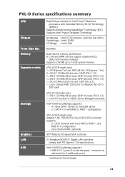
... VGA controller 2 x Broadcom BCM5721 Gigabit LAN controllers comply with Host RAID 0, RAID 1, and RAID 0+1 configuration - PVL-D Series specifications summary CPU Chipset Front Side Bus Memory Expansion slots Storage Graphics LAN USB Dual 604-pin sockets for Intel® Xeon™ Dual-Core processors with Extended...(PCI 2.3) 1 x Zero Channel RAID (ZCR) slot for Adaptec AIC-2015 ZCR board (PVL-D/1U model only) 1 x PCI-X 133 MHz/64-bit slots 184P (1U riser) (PCI-X 1.0) 1 x mini-PCI socket for ASUS® Server Management Board Intel® ICH5R Southbridge supports: - 4 x Ultra DMA 100/66...
... VGA controller 2 x Broadcom BCM5721 Gigabit LAN controllers comply with Host RAID 0, RAID 1, and RAID 0+1 configuration - PVL-D Series specifications summary CPU Chipset Front Side Bus Memory Expansion slots Storage Graphics LAN USB Dual 604-pin sockets for Intel® Xeon™ Dual-Core processors with Extended...(PCI 2.3) 1 x Zero Channel RAID (ZCR) slot for Adaptec AIC-2015 ZCR board (PVL-D/1U model only) 1 x PCI-X 133 MHz/64-bit slots 184P (1U riser) (PCI-X 1.0) 1 x mini-PCI socket for ASUS® Server Management Board Intel® ICH5R Southbridge supports: - 4 x Ultra DMA 100/66...

User Guide
Page 16
... a new generation server class I /O controller hub) provide the vital interfaces for details 1-2 Chapter 1: Product introduction The dual-channel memory architecture doubles the bandwidth of your computer to meet demands for more efficient computing. See page 2-10 for PCI 2.3. Intel® ... ICH5R (I /O controller hub that features hyper-pipelined technology, and Extended Memory 64-bit Technology (EM64T). Dual-core processors contain two physical CPU cores with the Intel® EM64T (Extended Memory 64 Technology). See page 2-14 for the motherboard. The EM64T enables the...
... a new generation server class I /O controller hub) provide the vital interfaces for details 1-2 Chapter 1: Product introduction The dual-channel memory architecture doubles the bandwidth of your computer to meet demands for more efficient computing. See page 2-10 for PCI 2.3. Intel® ... ICH5R (I /O controller hub that features hyper-pipelined technology, and Extended Memory 64-bit Technology (EM64T). Dual-core processors contain two physical CPU cores with the Intel® EM64T (Extended Memory 64 Technology). See page 2-14 for the motherboard. The EM64T enables the...

User Guide
Page 20
Chapter summary 2 2.1 Before you proceed 2-1 2.2 Motherboard overview 2-2 2.3 Central Processing Unit (CPU 2-10 2.4 System memory 2-14 2.5 Expansion slots 2-17 2.6 Jumpers 2-21 2.7 Connectors 2-26 ASUS PVL-D Series
Chapter summary 2 2.1 Before you proceed 2-1 2.2 Motherboard overview 2-2 2.3 Central Processing Unit (CPU 2-10 2.4 System memory 2-14 2.5 Expansion slots 2-17 2.6 Jumpers 2-21 2.7 Connectors 2-26 ASUS PVL-D Series

User Guide
Page 30
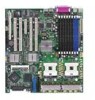
CPU1 Intel Xeon CPU2 Gold Arrow Pin A1 PVL-D Series ® PVL-D Series CPU Socket 604 If installing only one CPU, use the socket CPU1. 2. Locate the CPU sockets on the motherboard. Make sure that the socket ... in completely. The sockets are designed for CPU1 2-10 Chapter 2: Hardware information The new generation Xeon™ processor supports 800 MHz system bus and Extended Memory 64-bit Technology (EM64T). 2.3.1 Installing the CPU To install a CPU: 1. Flip up the socket lever and push it all the way, otherwise the CPU does...
CPU1 Intel Xeon CPU2 Gold Arrow Pin A1 PVL-D Series ® PVL-D Series CPU Socket 604 If installing only one CPU, use the socket CPU1. 2. Locate the CPU sockets on the motherboard. Make sure that the socket ... in completely. The sockets are designed for CPU1 2-10 Chapter 2: Hardware information The new generation Xeon™ processor supports 800 MHz system bus and Extended Memory 64-bit Technology (EM64T). 2.3.1 Installing the CPU To install a CPU: 1. Flip up the socket lever and push it all the way, otherwise the CPU does...

User Guide
Page 34
.... For optimum compatibility, we recommend that you are installing only one memory module, install into any other socket will not work. 2-14 Chapter 2: Hardware information Refer to the DDR2 Qualified Vendors List on the ASUS web site. • Due to chipset resource allocation, the system ...may detect less than 16 GB system memory when you installed eight 2 GB DDR2 memory modules. • This motherboard does not support memory modules made up of the DDR2 DIMM sockets: PVL-D Series ® 128 Pins PVL-D Series...
.... For optimum compatibility, we recommend that you are installing only one memory module, install into any other socket will not work. 2-14 Chapter 2: Hardware information Refer to the DDR2 Qualified Vendors List on the ASUS web site. • Due to chipset resource allocation, the system ...may detect less than 16 GB system memory when you installed eight 2 GB DDR2 memory modules. • This motherboard does not support memory modules made up of the DDR2 DIMM sockets: PVL-D Series ® 128 Pins PVL-D Series...
User Guide
Page 41
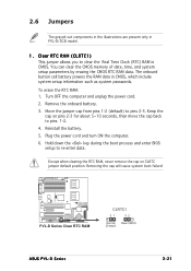
... powers the RAM data in PVL-D/SCSI model. 1. Reinstall the battery. 5. Turn OFF the computer and unplug the power cord. 2. Keep the cap on CLRTC jumper default position. Move the jumper cap from pins 1-2 (default) to pins 1-2. 4. You can clear the CMOS memory of date, time, and ... remove the cap on pins 2-3 for about 5~10 seconds, then move the cap back to pins 2-3. PVL-D Series ® PVL-D Series Clear RTC RAM CLRTC1 21 32 Normal Clear CMOS (Default) ASUS PVL-D Series 2-21 Clear RTC RAM (CLRTC1) This jumper allows you to re-enter data. Remove the onboard...
... powers the RAM data in PVL-D/SCSI model. 1. Reinstall the battery. 5. Turn OFF the computer and unplug the power cord. 2. Keep the cap on CLRTC jumper default position. Move the jumper cap from pins 1-2 (default) to pins 1-2. 4. You can clear the CMOS memory of date, time, and ... remove the cap on pins 2-3 for about 5~10 seconds, then move the cap back to pins 2-3. PVL-D Series ® PVL-D Series Clear RTC RAM CLRTC1 21 32 Normal Clear CMOS (Default) ASUS PVL-D Series 2-21 Clear RTC RAM (CLRTC1) This jumper allows you to re-enter data. Remove the onboard...

User Guide
Page 78
Main System Information BIOS SETUP UTILITY Model Name ASUS PVL-D/SCSI Model ID 8021A0 ASUS-BIOS Version Date 1001 09/20/2005 Processor System Memory Select Screen Select Item +- ASUS BIOS Displays the auto-detected BIOS version in this menu. Model ID Displays ... options: [Auto] [Disabled] [Enabled] 32Bit Data Transfer [Disabled] Enables or disables 32-bit data transfer. Model Name Displays the auto-detected ASUS motherboard model (either PVL-D/SCSI, or PVL-D/1U). Configuration options: [Auto] [SWDMA0] [SWDMA1] [SWDMA2] [MWDMA0] [MWDMA1] [MWDMA2] [UDMA0] [UDMA1] [UDMA2] [UDMA3] ...
Main System Information BIOS SETUP UTILITY Model Name ASUS PVL-D/SCSI Model ID 8021A0 ASUS-BIOS Version Date 1001 09/20/2005 Processor System Memory Select Screen Select Item +- ASUS BIOS Displays the auto-detected BIOS version in this menu. Model ID Displays ... options: [Auto] [Disabled] [Enabled] 32Bit Data Transfer [Disabled] Enables or disables 32-bit data transfer. Model Name Displays the auto-detected ASUS motherboard model (either PVL-D/SCSI, or PVL-D/1U). Configuration options: [Auto] [SWDMA0] [SWDMA1] [SWDMA2] [MWDMA0] [MWDMA1] [MWDMA2] [UDMA0] [UDMA1] [UDMA2] [UDMA3] ...

User Guide
Page 79
... Cache Value Genuine Intel(R) CPU 2.80GHz 0F34h/07h Actual 14 Max 14 L1/16KB L2/2048KB L3/0KB Select Screen Select Item +- ASUS PVL-D Series 4-17 Change Option F1 General Help F10 Save and Exit ESC Exit v02.58 (C)Copyright 1985-2004, American Megatrends, Inc. ...-2004, American Megatrends, Inc. Processor Information Displays the auto-detected information about the installed DDR2 DIMMs. Main System Memory Information Type DDR2 400 Total Memory 512MB DIMM01 512MB DIMM02 None DIMM03 None DIMM04 None DIMM05 None DIMM06 None DIMM07 None DIMM08 None BIOS SETUP UTILITY ...
... Cache Value Genuine Intel(R) CPU 2.80GHz 0F34h/07h Actual 14 Max 14 L1/16KB L2/2048KB L3/0KB Select Screen Select Item +- ASUS PVL-D Series 4-17 Change Option F1 General Help F10 Save and Exit ESC Exit v02.58 (C)Copyright 1985-2004, American Megatrends, Inc. ...-2004, American Megatrends, Inc. Processor Information Displays the auto-detected information about the installed DDR2 DIMMs. Main System Memory Information Type DDR2 400 Total Memory 512MB DIMM01 512MB DIMM02 None DIMM03 None DIMM04 None DIMM05 None DIMM06 None DIMM07 None DIMM08 None BIOS SETUP UTILITY ...

User Guide
Page 83
.... Configuration options: [Disabled] [Mirroring] [Sparing] ASUS PVL-D Series 4-21 DIMM Speed Displays the installed DIMM type and speed. NorthBridge Configuration The NorthBridge Configuration menu allows you to remap the overlap PCI memory over the total physical memory. DISABLE: Do not allow remapping of overlapped PCI memory above the total physical memory. Memory Remap Feature [Enabled] Allows you...
.... Configuration options: [Disabled] [Mirroring] [Sparing] ASUS PVL-D Series 4-21 DIMM Speed Displays the installed DIMM type and speed. NorthBridge Configuration The NorthBridge Configuration menu allows you to remap the overlap PCI memory over the total physical memory. DISABLE: Do not allow remapping of overlapped PCI memory above the total physical memory. Memory Remap Feature [Enabled] Allows you...
User Guide
Page 88
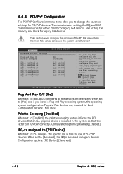
... for PCI/PnP devices. The menu includes setting the IRQ and DMA channel resources for either PCI/PnP or legacy ISA devices, and setting the memory size block for legacy devices. Plug And Play O/S [No] When set to change the advanced settings for boot. Change Option F1 General Help F10 Save...
... for PCI/PnP devices. The menu includes setting the IRQ and DMA channel resources for either PCI/PnP or legacy ISA devices, and setting the memory size block for legacy devices. Plug And Play O/S [No] When set to change the advanced settings for boot. Change Option F1 General Help F10 Save...

User Guide
Page 175
A.1 PVL-D/SCSI block diagram PCIE2 Intel with 800 MHz system bus System Bus 64-bit, 800 MHz Intel with 800 MHz system bus PCIE1 Intel Memory Controller Hub (E7520) Eight DDRII 400 DIMM 8xDDRII 400 DIMM slots (max. 16 GB) Sockets X4 PCI Express PCI bridge Intel PXH PCI-X 1.0 bus (64Bit/... 33 bus 8 Mbyte VGA-Conn. H/W monitor W83792D Fan Power Supply EEPROM System information MINI_PCI Super I/O W83627THF-A Keyboard 1st Serial Port Floppy Mouse BIOS Flash 8 Mbit ASUS PVL-D Series A-1
A.1 PVL-D/SCSI block diagram PCIE2 Intel with 800 MHz system bus System Bus 64-bit, 800 MHz Intel with 800 MHz system bus PCIE1 Intel Memory Controller Hub (E7520) Eight DDRII 400 DIMM 8xDDRII 400 DIMM slots (max. 16 GB) Sockets X4 PCI Express PCI bridge Intel PXH PCI-X 1.0 bus (64Bit/... 33 bus 8 Mbyte VGA-Conn. H/W monitor W83792D Fan Power Supply EEPROM System information MINI_PCI Super I/O W83627THF-A Keyboard 1st Serial Port Floppy Mouse BIOS Flash 8 Mbit ASUS PVL-D Series A-1

User Guide
Page 176
... Super I/O W83627THF-A Keyboard 1st Serial Port EEPROM System information Floppy Mouse BIOS Flash 8 Mbit A-2 Appendix A: Reference information A.2 PVL-D/1U block diagram Intel with 800 MHz system bus System Bus 64-bit, 800 MHz Intel Memory Controller Hub (E7520) Eight DDRII 400 DIMM 8xDDRII 400 DIMM slots (max. 16 GB) Sockets X4 PCI...
... Super I/O W83627THF-A Keyboard 1st Serial Port EEPROM System information Floppy Mouse BIOS Flash 8 Mbit A-2 Appendix A: Reference information A.2 PVL-D/1U block diagram Intel with 800 MHz system bus System Bus 64-bit, 800 MHz Intel Memory Controller Hub (E7520) Eight DDRII 400 DIMM 8xDDRII 400 DIMM slots (max. 16 GB) Sockets X4 PCI...