User Guide
Page 3
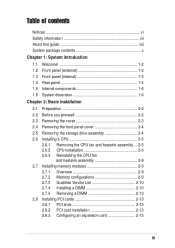
... 1-6 Chapter 2: Basic installation 2.1 Preparation 2-2 2.2 Before you proceed 2-2 2.3 Removing the cover 2-3 2.4 Removing the front panel cover 2-4 2.5 Removing the storage drive assembly 2-4 2.6 Installing a CPU 2-5 2.6.1 Removing the CPU fan and heatsink assembly ... 2-5 2.6.2 CPU installation 2-6 2.6.3 Reinstalling the CPU fan and heatsink assembly 2-8 2.7 Installing memory modules 2-9 2.7.1 Overview 2-9 2.7.2 Memory configurations 2-9 2.7.3 Qualified Vendor List 2-10 2.7.4 Installing a DIMM 2-10 2.7.5 Removing a DIMM 2-13...
... 1-6 Chapter 2: Basic installation 2.1 Preparation 2-2 2.2 Before you proceed 2-2 2.3 Removing the cover 2-3 2.4 Removing the front panel cover 2-4 2.5 Removing the storage drive assembly 2-4 2.6 Installing a CPU 2-5 2.6.1 Removing the CPU fan and heatsink assembly ... 2-5 2.6.2 CPU installation 2-6 2.6.3 Reinstalling the CPU fan and heatsink assembly 2-8 2.7 Installing memory modules 2-9 2.7.1 Overview 2-9 2.7.2 Memory configurations 2-9 2.7.3 Qualified Vendor List 2-10 2.7.4 Installing a DIMM 2-10 2.7.5 Removing a DIMM 2-13...
User Guide
Page 5
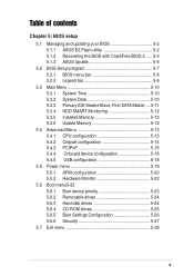
... of contents Chapter 5: BIOS setup 5.1 Managing and updating your BIOS 5-2 5.1.1 ASUS EZ Flash utility 5-2 5.1.2 Recovering the BIOS with CrashFree BIOS 2 ..... 5-3 5.1.3 ASUS Update 5-5 5.2 BIOS Setup program 5-7 5.2.1 BIOS menu bar 5-8 5.2.2 Legend bar... 5-8 5.3 Main Menu 5-10 5.3.1 System Time 5-10 5.3.2 System Date 5-10 5.3.3 Primary IDE Master/Slave; First SATA Master ....5-11 5.3.4 HDD SMART Monitoring 5-12 5.3.5 Installed Memory 5-12 5.3.6 Usable Memory 5-12 5.4 Advanced Menu 5-13 5.4.1 CPU...
... of contents Chapter 5: BIOS setup 5.1 Managing and updating your BIOS 5-2 5.1.1 ASUS EZ Flash utility 5-2 5.1.2 Recovering the BIOS with CrashFree BIOS 2 ..... 5-3 5.1.3 ASUS Update 5-5 5.2 BIOS Setup program 5-7 5.2.1 BIOS menu bar 5-8 5.2.2 Legend bar... 5-8 5.3 Main Menu 5-10 5.3.1 System Time 5-10 5.3.2 System Date 5-10 5.3.3 Primary IDE Master/Slave; First SATA Master ....5-11 5.3.4 HDD SMART Monitoring 5-12 5.3.5 Installed Memory 5-12 5.3.6 Usable Memory 5-12 5.4 Advanced Menu 5-13 5.4.1 CPU...
User Guide
Page 10
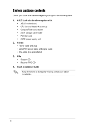
... system package for the following items. 1. CDs • Support CD • Recover PRO CD 4. x System package contents Check your retailer immediately. ASUS book size barebone system with: • ASUS motherboard • CPU fan and heatsink assembly • CompactFlash card reader • 3-in-1 storage card reader • PCI riser card • 250W power supply...
... system package for the following items. 1. CDs • Support CD • Recover PRO CD 4. x System package contents Check your retailer immediately. ASUS book size barebone system with: • ASUS motherboard • CPU fan and heatsink assembly • CompactFlash card reader • 3-in-1 storage card reader • PCI riser card • 250W power supply...
User Guide
Page 16
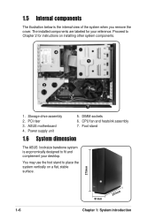
Proceed to Chapter 2 for your desktop. Power supply unit 5. CPU fan and heatsink assembly 7. Storage drive assembly 2. DIMM sockets 6. Foot stand 1.6 System dimension The ASUS booksize barebone system is the internal view of the system when you remove the cover. ASUS motherboard 4. You may use the foot stand to fit and complement your reference...
Proceed to Chapter 2 for your desktop. Power supply unit 5. CPU fan and heatsink assembly 7. Storage drive assembly 2. DIMM sockets 6. Foot stand 1.6 System dimension The ASUS booksize barebone system is the internal view of the system when you remove the cover. ASUS motherboard 4. You may use the foot stand to fit and complement your reference...
User Guide
Page 18
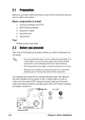
... disk drive 5. SB_PWR ON Standby Power OFF Powered Off ® Onboard LED 2-2 Chapter 2: Basic installation Basic components to install in the system. Central processing unit (CPU) 2. Optical drive Tool Phillips (cross) screw driver 2.2 Before you proceed Take note of the following precautions before you install components into the system. • Use...
... disk drive 5. SB_PWR ON Standby Power OFF Powered Off ® Onboard LED 2-2 Chapter 2: Basic installation Basic components to install in the system. Central processing unit (CPU) 2. Optical drive Tool Phillips (cross) screw driver 2.2 Before you proceed Take note of the following precautions before you install components into the system. • Use...
User Guide
Page 20
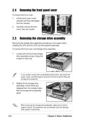
..., make sure to hold or support it aside. 2.5 Removing the storage drive assembly Removing the storage drive assembly provides you more space when installing the CPU and the CPU fan and heatsink assembly.
..., make sure to hold or support it aside. 2.5 Removing the storage drive assembly Removing the storage drive assembly provides you more space when installing the CPU and the CPU fan and heatsink assembly.
User Guide
Page 21
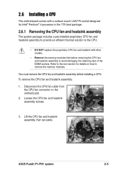
... to remove the memory modules. To remove the CPU fan and heatsink assembly: 1. Disconnect the CPU fan cable from the CPU fan connector on how to avoid damaging the retaining clips of the DIMM sockets. ASUS Pundit P1-PH1 system 2-5 Loosen the CPU fan and heatsink assembly screws. 3. 2.6 Installing a CPU The motherboard comes with a surface mount LGA775 socket...
... to remove the memory modules. To remove the CPU fan and heatsink assembly: 1. Disconnect the CPU fan cable from the CPU fan connector on how to avoid damaging the retaining clips of the DIMM sockets. ASUS Pundit P1-PH1 system 2-5 Loosen the CPU fan and heatsink assembly screws. 3. 2.6 Installing a CPU The motherboard comes with a surface mount LGA775 socket...
User Guide
Page 22
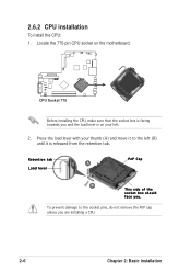
To prevent damage to the left . 2. Retention tab A Load lever PnP Cap B This side of the socket box should face you are installing a CPU. 2-6 Chapter 2: Basic installation 2.6.2 CPU installation To install the CPU: 1. Locate the 775-pin CPU socket on the motherboard. ® CPU Socket 775 Before installing the CPU, make sure that the socket box is facing towards you and the load lever is on your thumb (A) and move it to the socket pins, do not remove the PnP cap unless you . Press the load lever with your left (B) until it is released from the retention tab.
To prevent damage to the left . 2. Retention tab A Load lever PnP Cap B This side of the socket box should face you are installing a CPU. 2-6 Chapter 2: Basic installation 2.6.2 CPU installation To install the CPU: 1. Locate the 775-pin CPU socket on the motherboard. ® CPU Socket 775 Before installing the CPU, make sure that the socket box is facing towards you and the load lever is on your thumb (A) and move it to the socket pins, do not remove the PnP cap unless you . Press the load lever with your left (B) until it is released from the retention tab.
User Guide
Page 23
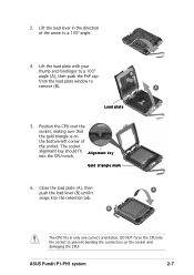
...the socket, making sure that the gold triangle is on the socket and damaging the CPU! Close the load plate (A), then A push the load lever (B) until it snaps into the CPU notch. Lift the load plate with your thumb and forefinger to a 100º angle... alignment key should fit A l i g n m e n t k e y into the retention tab. B The CPU fits in the direction of the socket. B A Load plate 5. DO NOT force the CPU into the socket to prevent bending the connectors on the bottom-left corner of the arrow to remove (B). Gold triangle mark 6. 3. ASUS Pundit P1-PH1 system 2-7
...the socket, making sure that the gold triangle is on the socket and damaging the CPU! Close the load plate (A), then A push the load lever (B) until it snaps into the CPU notch. Lift the load plate with your thumb and forefinger to a 100º angle... alignment key should fit A l i g n m e n t k e y into the retention tab. B The CPU fits in the direction of the socket. B A Load plate 5. DO NOT force the CPU into the socket to prevent bending the connectors on the bottom-left corner of the arrow to remove (B). Gold triangle mark 6. 3. ASUS Pundit P1-PH1 system 2-7
User Guide
Page 24
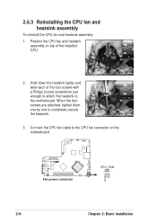
..., tighten them one by one to the CPU fan connector on top of the four screws with a Philips (cross) screwdriver just enough to attach the heatsink to the motherboard. 2.6.3 Reinstalling the CPU fan and heatsink assembly To reinstall the CPU fan and heatsink assembly: 1. Hold down... the heatsink lightly and twist each of the installed CPU. 2. Position the CPU fan and heatsink assembly on the motherboard. ® Fan power...
..., tighten them one by one to the CPU fan connector on top of the four screws with a Philips (cross) screwdriver just enough to attach the heatsink to the motherboard. 2.6.3 Reinstalling the CPU fan and heatsink assembly To reinstall the CPU fan and heatsink assembly: 1. Hold down... the heatsink lightly and twist each of the installed CPU. 2. Position the CPU fan and heatsink assembly on the motherboard. ® Fan power...
User Guide
Page 27
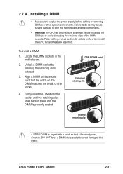
... snap back in the motherboard. 2. Unlock a DIMM socket by pressing the retaining clips outward. 3. Firmly insert the DIMM into a socket to reinstall the CPU fan and heatsink assembly. ASUS Pundit P1-PH1 system 2-11 2.7.4 Installing a DIMM • Make sure to avoid damaging the retaining clips of the DIMM sockets. Align a DIMM on how to...
... snap back in the motherboard. 2. Unlock a DIMM socket by pressing the retaining clips outward. 3. Firmly insert the DIMM into a socket to reinstall the CPU fan and heatsink assembly. ASUS Pundit P1-PH1 system 2-11 2.7.4 Installing a DIMM • Make sure to avoid damaging the retaining clips of the DIMM sockets. Align a DIMM on how to...
User Guide
Page 28
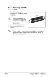
2.7.5 Removing a DIMM To remove a DIMM: 1. Incorrect removal sequence may damage the DIMM socket retaining clips. 2-12 Chapter 2: Basic installation Support the DIMM lightly with extra force. 2. Simultaneously press the retaining clips outward to unlock the DIMM. Remove the CPU fan and heatsink assembly before removing the memory module(s). Remove the DIMM from the socket. The DIMM might get damaged when it flips out with your fingers when pressing the retaining clips.
2.7.5 Removing a DIMM To remove a DIMM: 1. Incorrect removal sequence may damage the DIMM socket retaining clips. 2-12 Chapter 2: Basic installation Support the DIMM lightly with extra force. 2. Simultaneously press the retaining clips outward to unlock the DIMM. Remove the CPU fan and heatsink assembly before removing the memory module(s). Remove the DIMM from the socket. The DIMM might get damaged when it flips out with your fingers when pressing the retaining clips.
User Guide
Page 47
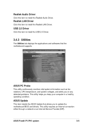
... Probe This utility continuously monitors vital system information such as fan rotations, CPU temperature, and system voltages, and alerts you on any detected problems. This utility helps you to install the Realtek Audio Driver. ASUS Pundit P1-PH1 system 3-5 Realtek LAN Driver Click this item to install the Realtek LAN Driver. This utility requires...
... Probe This utility continuously monitors vital system information such as fan rotations, CPU temperature, and system voltages, and alerts you on any detected problems. This utility helps you to install the Realtek Audio Driver. ASUS Pundit P1-PH1 system 3-5 Realtek LAN Driver Click this item to install the Realtek LAN Driver. This utility requires...
User Guide
Page 58
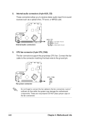
... you to the ground pin. Rotation +12V GND ® CPU_FAN Fan power connector Do not forget to connect the fan cables to the fan connectors. CPU fan connector (3-pin CPU_FAN) The fan connectors support the proprietary...
... you to the ground pin. Rotation +12V GND ® CPU_FAN Fan power connector Do not forget to connect the fan cables to the fan connectors. CPU fan connector (3-pin CPU_FAN) The fan connectors support the proprietary...

User Guide
Page 71
...the Advanced menu items. Incorrect field values may cause the system to 3, Should Be "Disabled" for the CPU and other system devices. CPU Configuration CPU Type Intel Pentium(R) D CPU Speed 2.80GHz Cache RAM 1024 K x2 Current FSB Frequency 200 MHz Thermal Management [TM 1] x TM2...Select Menu Item Specific Help Set Limit CPUID MaxVal to malfunction. CPU Configuration Chipset PCIPnP Onboard Device Configuration USB Configuration Select Menu Item Specific Help Press [Enter] to change the settings for WinXP ASUS Pundit P1-PH1 system 5-13 5.4 Advanced Menu The Advanced menu items ...
...the Advanced menu items. Incorrect field values may cause the system to 3, Should Be "Disabled" for the CPU and other system devices. CPU Configuration CPU Type Intel Pentium(R) D CPU Speed 2.80GHz Cache RAM 1024 K x2 Current FSB Frequency 200 MHz Thermal Management [TM 1] x TM2...Select Menu Item Specific Help Set Limit CPUID MaxVal to malfunction. CPU Configuration Chipset PCIPnP Onboard Device Configuration USB Configuration Select Menu Item Specific Help Press [Enter] to change the settings for WinXP ASUS Pundit P1-PH1 system 5-13 5.4 Advanced Menu The Advanced menu items ...
User Guide
Page 80
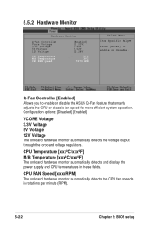
... 3.3V Voltage 5V Voltage 12V Voltage The onboard hardware monitor automatically detects the voltage output through the onboard voltage regulators. CPU Temperature [xxxºC/xxxºF] M/B Temperature [xxxºC/xxxºF] The onboard hardware monitor automatically detects and display the power supply and...3.3V Voltage 5V Voltage 12V Voltage CPU Temperature M/B Temperature CPU FAN Speed [Enabled] [1.23V] 3.26V 5.02V 12.28V 54oC 38oC 7273 RPM Select Menu Item Specific Help Press [Enter] to enable or disable the ASUS Q-Fan feature that smartly adjusts the CPU or chassis fan speed for more ...
... 3.3V Voltage 5V Voltage 12V Voltage The onboard hardware monitor automatically detects the voltage output through the onboard voltage regulators. CPU Temperature [xxxºC/xxxºF] M/B Temperature [xxxºC/xxxºF] The onboard hardware monitor automatically detects and display the power supply and...3.3V Voltage 5V Voltage 12V Voltage CPU Temperature M/B Temperature CPU FAN Speed [Enabled] [1.23V] 3.26V 5.02V 12.28V 54oC 38oC 7273 RPM Select Menu Item Specific Help Press [Enter] to enable or disable the ASUS Q-Fan feature that smartly adjusts the CPU or chassis fan speed for more ...

