User Guide
Page 3
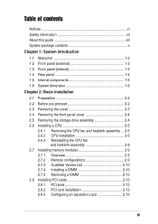
... 2-2 2.3 Removing the cover 2-3 2.4 Removing the front panel cover 2-4 2.5 Removing the storage drive assembly 2-4 2.6 Installing a CPU 2-5 2.6.1 Removing the CPU fan and heatsink assembly ... 2-5 2.6.2 CPU installation 2-6 2.6.3 Reinstalling the CPU fan and heatsink assembly 2-8 2.7 Installing memory modules 2-9 2.7.1 Overview 2-9 2.7.2 Memory configurations 2-9 2.7.3 Qualified Vendor List 2-10 2.7.4 Installing a DIMM 2-10 2.7.5 Removing a DIMM 2-13 2.8 Installing PCI cards 2-13 2.8.1 PCI slots 2-13 2.8.2 PCI card installation 2-13 2.8.3 Configuring an expansion card 2-15 iii
... 2-2 2.3 Removing the cover 2-3 2.4 Removing the front panel cover 2-4 2.5 Removing the storage drive assembly 2-4 2.6 Installing a CPU 2-5 2.6.1 Removing the CPU fan and heatsink assembly ... 2-5 2.6.2 CPU installation 2-6 2.6.3 Reinstalling the CPU fan and heatsink assembly 2-8 2.7 Installing memory modules 2-9 2.7.1 Overview 2-9 2.7.2 Memory configurations 2-9 2.7.3 Qualified Vendor List 2-10 2.7.4 Installing a DIMM 2-10 2.7.5 Removing a DIMM 2-13 2.8 Installing PCI cards 2-13 2.8.1 PCI slots 2-13 2.8.2 PCI card installation 2-13 2.8.3 Configuring an expansion card 2-15 iii
User Guide
Page 13
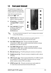
... . Open the front panel door by 9 pressing the mark. 8. S/PDIF In port . ASUS Pundit P1-PH1 system 1-3 Reset button . This port connects a headphone with a stereo mini-plug. 16. This port connects your audio system for IEEE 1394-compliant audio/video devices, storage peripherals, ... 1394 port . USB 2.0 ports . This slot is for connecting USB 2.0 devices such as a mouse, printer, scanner, camera, PDA, and others. 17. 1.3 Front panel (internal) The optical drive, storage card reader, and several I /O door if a storage card is 15 14 for Memory Stick®/Pro&#...
... . Open the front panel door by 9 pressing the mark. 8. S/PDIF In port . ASUS Pundit P1-PH1 system 1-3 Reset button . This port connects a headphone with a stereo mini-plug. 16. This port connects your audio system for IEEE 1394-compliant audio/video devices, storage peripherals, ... 1394 port . USB 2.0 ports . This slot is for connecting USB 2.0 devices such as a mouse, printer, scanner, camera, PDA, and others. 17. 1.3 Front panel (internal) The optical drive, storage card reader, and several I /O door if a storage card is 15 14 for Memory Stick®/Pro&#...
User Guide
Page 18
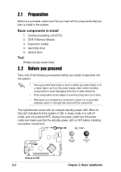
... to install 1. DDR II Memory Module 3. Expansion card(s) 4. Unplug the power cable from the power outlet and make sure that you have all the components that you plan to install in soft-off mode, and not powered OFF. When lit, this LED indicates ...ON Standby Power OFF Powered Off ® Onboard LED 2-2 Chapter 2: Basic installation Hard disk drive 5. The motherboard comes with the component. 2.1 Preparation Before you proceed, make sure that came with an onboard standby power LED. Central processing unit (CPU) 2. Optical drive Tool Phillips (cross) screw driver 2.2 Before...
... to install 1. DDR II Memory Module 3. Expansion card(s) 4. Unplug the power cable from the power outlet and make sure that you have all the components that you plan to install in soft-off mode, and not powered OFF. When lit, this LED indicates ...ON Standby Power OFF Powered Off ® Onboard LED 2-2 Chapter 2: Basic installation Hard disk drive 5. The motherboard comes with the component. 2.1 Preparation Before you proceed, make sure that came with an onboard standby power LED. Central processing unit (CPU) 2. Optical drive Tool Phillips (cross) screw driver 2.2 Before...
User Guide
Page 19
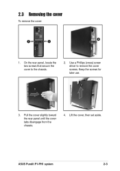
ASUS Pundit P1-PH1 system 2-3 On the rear panel, locate the two screws that secure the cover to remove the cover screws. Pull the cover slightly toward the rear panel until the cover tabs disengage from the chassis. 4. Keep the screws for later use. 4 3 3. 2.3 Removing the cover To remove the cover: 2 1 1 1. Use a Phillips (cross) screw driver to the chassis. 2. Lift the cover, then set aside.
ASUS Pundit P1-PH1 system 2-3 On the rear panel, locate the two screws that secure the cover to remove the cover screws. Pull the cover slightly toward the rear panel until the cover tabs disengage from the chassis. 4. Keep the screws for later use. 4 3 3. 2.3 Removing the cover To remove the cover: 2 1 1 1. Use a Phillips (cross) screw driver to the chassis. 2. Lift the cover, then set aside.
User Guide
Page 21
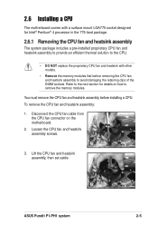
ASUS Pundit P1-PH1 system 2-5 You must remove the CPU fan and heatsink assembly before removing the CPU fan and heatsink assembly to remove the memory modules. Loosen the CPU fan and heatsink assembly screws. 3. Lift the CPU fan and heatsink assembly, then set aside. To remove the CPU fan and heatsink assembly: 1. Disconnect the CPU fan cable from the CPU fan connector on how to avoid damaging the retaining clips of the DIMM sockets...
ASUS Pundit P1-PH1 system 2-5 You must remove the CPU fan and heatsink assembly before removing the CPU fan and heatsink assembly to remove the memory modules. Loosen the CPU fan and heatsink assembly screws. 3. Lift the CPU fan and heatsink assembly, then set aside. To remove the CPU fan and heatsink assembly: 1. Disconnect the CPU fan cable from the CPU fan connector on how to avoid damaging the retaining clips of the DIMM sockets...
User Guide
Page 22
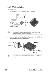
2.6.2 CPU installation To install the CPU: 1. Press the load lever with your left (B) until it is on your thumb (A) and move it to the socket pins, do not remove the PnP cap unless you . To prevent damage to the left . 2. Locate the 775-pin CPU socket on the motherboard. ® CPU Socket 775 Before installing the CPU, make sure that the socket box is facing towards you and the load lever is released from the retention tab. Retention tab A Load lever PnP Cap B This side of the socket box should face you are installing a CPU. 2-6 Chapter 2: Basic installation
2.6.2 CPU installation To install the CPU: 1. Press the load lever with your left (B) until it is on your thumb (A) and move it to the socket pins, do not remove the PnP cap unless you . To prevent damage to the left . 2. Locate the 775-pin CPU socket on the motherboard. ® CPU Socket 775 Before installing the CPU, make sure that the socket box is facing towards you and the load lever is released from the retention tab. Retention tab A Load lever PnP Cap B This side of the socket box should face you are installing a CPU. 2-6 Chapter 2: Basic installation
User Guide
Page 23
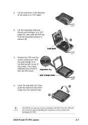
...e y into the retention tab. B The CPU fits in the direction of the socket. ASUS Pundit P1-PH1 system 2-7 Lift the load plate with your thumb and forefinger to a 100º angle (A), then push the PnP cap from the load plate window to prevent bending the connectors on the bottom-...left corner of the arrow to a 135º angle. 4. DO NOT force the CPU into the socket to remove...
...e y into the retention tab. B The CPU fits in the direction of the socket. ASUS Pundit P1-PH1 system 2-7 Lift the load plate with your thumb and forefinger to a 100º angle (A), then push the PnP cap from the load plate window to prevent bending the connectors on the bottom-...left corner of the arrow to a 135º angle. 4. DO NOT force the CPU into the socket to remove...
User Guide
Page 27
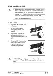
... outward. 3. ASUS Pundit P1-PH1 system 2-11 Locate the DIMM sockets in only one direction. DDR II DIMM notch Unlocked retaining clip Locked retaining clip A DDR II DIMM is properly seated. 2.7.4 Installing a DIMM • Make sure to reinstall the CPU fan and heatsink assembly. Align a DIMM on the socket such that it fits in the motherboard. 2. Firmly...
... outward. 3. ASUS Pundit P1-PH1 system 2-11 Locate the DIMM sockets in only one direction. DDR II DIMM notch Unlocked retaining clip Locked retaining clip A DDR II DIMM is properly seated. 2.7.4 Installing a DIMM • Make sure to reinstall the CPU fan and heatsink assembly. Align a DIMM on the socket such that it fits in the motherboard. 2. Firmly...
User Guide
Page 29
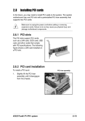
... and damage motherboard components. 2.8.1 PCI slots The PCI slots support PCI cards such as a LAN card, SCSI card, USB card, and other cards that comply with a preinstalled PCI riser assembly that supports two PCI cards. Make sure to the system. PCI riser assembly ASUS Pundit P1-PH1 system 2-13 Failure to do so may cause you may need to install PCI cards to unplug the power cord before adding or removing expansion cards. Slightly lift...
... and damage motherboard components. 2.8.1 PCI slots The PCI slots support PCI cards such as a LAN card, SCSI card, USB card, and other cards that comply with a preinstalled PCI riser assembly that supports two PCI cards. Make sure to the system. PCI riser assembly ASUS Pundit P1-PH1 system 2-13 Failure to do so may cause you may need to install PCI cards to unplug the power cord before adding or removing expansion cards. Slightly lift...
User Guide
Page 31
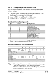
...the system unstable and the card inoperable. 2.8.3 Configuring an expansion card After installing the expansion card, configure the card by adjusting the software settings. 1. Turn on the system and change the necessary BIOS settings, if any. Install the software drivers for ISA or PCI devices. shared -- Onboard USB 2.0 controller -- -- -- shared -- Onboard VGA -- Onboard 1394 controller -- -- -- -- -- F G H -- -- -- -- -- -- -- -- -- -- -- -- -- -- -- -- -- -- -- -- -- -- -- -- used -- -- -- ASUS Pundit P1-PH1 system 2-15
...the system unstable and the card inoperable. 2.8.3 Configuring an expansion card After installing the expansion card, configure the card by adjusting the software settings. 1. Turn on the system and change the necessary BIOS settings, if any. Install the software drivers for ISA or PCI devices. shared -- Onboard USB 2.0 controller -- -- -- shared -- Onboard VGA -- Onboard 1394 controller -- -- -- -- -- F G H -- -- -- -- -- -- -- -- -- -- -- -- -- -- -- -- -- -- -- -- -- -- -- -- used -- -- -- ASUS Pundit P1-PH1 system 2-15
User Guide
Page 32
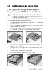
... chassis. 7. Insert the optical drive upside down with three screws. 2-16 Chapter 2: Basic installation Connect the 4-pin power plugs to the 5.25-inch bay, then secure it in the storage drive assembly. Configure your hard disk drive as a Master device. 2.9 Installing optical and storage drives 2.9.1 Optical and storage drives installation The system supports one UltraATA 100/66 IDE or one Serial ATA hard disk drive. To install...
... chassis. 7. Insert the optical drive upside down with three screws. 2-16 Chapter 2: Basic installation Connect the 4-pin power plugs to the 5.25-inch bay, then secure it in the storage drive assembly. Configure your hard disk drive as a Master device. 2.9 Installing optical and storage drives 2.9.1 Optical and storage drives installation The system supports one UltraATA 100/66 IDE or one Serial ATA hard disk drive. To install...

User Guide
Page 38
Lay the system upside down on a flat and stable surface. 2. Use your thumb to push the lock toward the rear panel until the foot stand tabs are released from the chassis holes. 4. Locate the foot stand lock. 3. Lift the foot stand, then set it aside. 1 Lock 2 3 2-22 Chapter 2: Basic installation 2.11.2 Removing the foot stand To remove the foot stand: 1.
Lay the system upside down on a flat and stable surface. 2. Use your thumb to push the lock toward the rear panel until the foot stand tabs are released from the chassis holes. 4. Locate the foot stand lock. 3. Lift the foot stand, then set it aside. 1 Lock 2 3 2-22 Chapter 2: Basic installation 2.11.2 Removing the foot stand To remove the foot stand: 1.

User Guide
Page 46
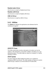
.... Install the necessary drivers to run the CD. 3.4.2 Drivers menu The drivers menu shows the available device drivers if the system detects installed devices. 3.4 Support CD information The support CD that came with the system contains useful software and several utility drivers that enhance the system features. • Screen display and driver options may not be the same for updates. 3.4.1 Running...
.... Install the necessary drivers to run the CD. 3.4.2 Drivers menu The drivers menu shows the available device drivers if the system detects installed devices. 3.4 Support CD information The support CD that came with the system contains useful software and several utility drivers that enhance the system features. • Screen display and driver options may not be the same for updates. 3.4.1 Running...
User Guide
Page 47
... ASUS Update that the motherboard supports. Realtek Audio Driver Click this item to install the Realtek LAN Driver. ASUS Pundit P1-PH1 system 3-5 Realtek LAN Driver Click this item to update the motherboard BIOS and drivers. USB 2.0 Driver Click this item to install the Realtek Audio Driver. ASUS PC Probe This utility continuously monitors vital system information such as fan rotations, CPU temperature, and system voltages, and alerts you on any detected problems...
... ASUS Update that the motherboard supports. Realtek Audio Driver Click this item to install the Realtek LAN Driver. ASUS Pundit P1-PH1 system 3-5 Realtek LAN Driver Click this item to update the motherboard BIOS and drivers. USB 2.0 Driver Click this item to install the Realtek Audio Driver. ASUS PC Probe This utility continuously monitors vital system information such as fan rotations, CPU temperature, and system voltages, and alerts you on any detected problems...

User Guide
Page 57
Serial port connector (10-1 pin COM1) This connector supports the rear panel serial port. ® Serial COM1 connector COM1 ASUS Pundit P1-PH1 system 4-7 6. The current Serial ATA interface allows up to 150 MB/s data transfer rate,...problem caused by the wide, flat ribbon cables of the Parallel ATA interface. • This motherboard does not support hot plug function for a Serial ATA hard disk drive. Serial ATA connector (7-pin SATA1) This next generation connector supports the thin Serial ATA cable for Serial ATA drive and connections. • Install Windows® XP™ Service...
Serial port connector (10-1 pin COM1) This connector supports the rear panel serial port. ® Serial COM1 connector COM1 ASUS Pundit P1-PH1 system 4-7 6. The current Serial ATA interface allows up to 150 MB/s data transfer rate,...problem caused by the wide, flat ribbon cables of the Parallel ATA interface. • This motherboard does not support hot plug function for a Serial ATA hard disk drive. Serial ATA connector (7-pin SATA1) This next generation connector supports the thin Serial ATA cable for Serial ATA drive and connections. • Install Windows® XP™ Service...
User Guide
Page 63
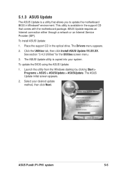
... in the optical drive. To install ASUS Update: 1. Launch the utility from the Windows desktop by clicking Start > Programs > ASUS > ASUSUpdate > ASUSUpdate. ASUS Pundit P1-PH1 system 5-5 Click the Utilities tab, then click Install ASUS Update VX.XX.XX. The ASUS Update utility is copied into your desired update method, then click Next. ASUS Update requires an Internet connection either through a network or an Internet Service Provider (ISP...
... in the optical drive. To install ASUS Update: 1. Launch the utility from the Windows desktop by clicking Start > Programs > ASUS > ASUSUpdate > ASUSUpdate. ASUS Pundit P1-PH1 system 5-5 Click the Utilities tab, then click Install ASUS Update VX.XX.XX. The ASUS Update utility is copied into your desired update method, then click Next. ASUS Update requires an Internet connection either through a network or an Internet Service Provider (ISP...
User Guide
Page 76
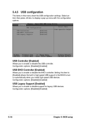
... the USB configuration settings. Configuration options: [Disabled] [Enabled] USB Legacy Support [Enabled] Allows you to turn on automatically when you install high speed USB devices. 5.4.5 USB configuration The items in the BIOS to enable or disable support for legacy USB devices. Select an item then press to enable or disable the USB controller. USB Configuration USB Controller USB EHCI Controller USB Legacy Support [Enabled] [Enabled] [Enabled] Select Menu Item Specific Help USB...
... the USB configuration settings. Configuration options: [Disabled] [Enabled] USB Legacy Support [Enabled] Allows you to turn on automatically when you install high speed USB devices. 5.4.5 USB configuration The items in the BIOS to enable or disable support for legacy USB devices. Select an item then press to enable or disable the USB controller. USB Configuration USB Controller USB EHCI Controller USB Legacy Support [Enabled] [Enabled] [Enabled] Select Menu Item Specific Help USB...
User Guide
Page 81
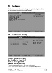
... boot device priority. Configuration options: [Removable] [Hard Disk] [CDROM] [Disabled] ASUS Pundit P1-PH1 system 5-23 Boot Device Priority Removable Drives Hard Disk Drives CDROM Drives Boot Settings Configuration Security Select Menu Item Specific Help 5.6.1 Boot device priority Boot Device Priority 1st Boot Device 2nd Boot Device 3rd Boot Device 4th Boot Device [Removable] [Hard Disk] [CDROM] [Disabled] Select Menu Item Specific Help Select your Boot Device Priority 1st Boot Device [Removable] 2nd Boot Device [Hard Disk] 3rd Boot Device [CDROM] 4th Boot...
... boot device priority. Configuration options: [Removable] [Hard Disk] [CDROM] [Disabled] ASUS Pundit P1-PH1 system 5-23 Boot Device Priority Removable Drives Hard Disk Drives CDROM Drives Boot Settings Configuration Security Select Menu Item Specific Help 5.6.1 Boot device priority Boot Device Priority 1st Boot Device 2nd Boot Device 3rd Boot Device 4th Boot Device [Removable] [Hard Disk] [CDROM] [Disabled] Select Menu Item Specific Help Select your Boot Device Priority 1st Boot Device [Removable] 2nd Boot Device [Hard Disk] 3rd Boot Device [CDROM] 4th Boot...

User Guide
Page 84
... the power-on self tests (POST) while booting to decrease the time needed to repeat. Configuration options: [250] [500] [750] [1000] 5-26 Chapter 5: BIOS setup This ...Setting is set to [Disabled], BIOS performs all the POST items. Configuration options: [Enabled] [Disabled] Bootup Num-Lock [On] Allows you to select the rate at which character repeats when you to x Typematic Rate (Chars/Sec) 6 skip certain tests x Typematic Delay (Msec) 250 while booting. 5.6.5 Boot Settings Configuration Boot Settings COnfiguration Select Menu Quick Boot [Enabled] Item Specific Help Boot...
... the power-on self tests (POST) while booting to decrease the time needed to repeat. Configuration options: [250] [500] [750] [1000] 5-26 Chapter 5: BIOS setup This ...Setting is set to [Disabled], BIOS performs all the POST items. Configuration options: [Enabled] [Disabled] Bootup Num-Lock [On] Allows you to select the rate at which character repeats when you to x Typematic Rate (Chars/Sec) 6 skip certain tests x Typematic Delay (Msec) 250 while booting. 5.6.5 Boot Settings Configuration Boot Settings COnfiguration Select Menu Quick Boot [Enabled] Item Specific Help Boot...

User Guide
Page 87
... are finished making your changes before exiting. ASUS Pundit P1-PH1 system 5-29 The CMOS RAM is sustained by an onboard backup battery and stays on even when the PC is turned off. If you attempt to exit the Setup program without saving your changes, the program ...& Discard Changes Load Setup Default Discard Changes Select Menu Item Specific Help This option saves data to save changes and exit. Pressing does not immediately exit this option, a confirmation window appears. If you made changes to fields other than system date, system time, and password, the BIOS asks for a confirmation...
... are finished making your changes before exiting. ASUS Pundit P1-PH1 system 5-29 The CMOS RAM is sustained by an onboard backup battery and stays on even when the PC is turned off. If you attempt to exit the Setup program without saving your changes, the program ...& Discard Changes Load Setup Default Discard Changes Select Menu Item Specific Help This option saves data to save changes and exit. Pressing does not immediately exit this option, a confirmation window appears. If you made changes to fields other than system date, system time, and password, the BIOS asks for a confirmation...


