

PSCH-SR User Manual English Version
Page 3
Features Contents Notices v Safety information vi About this guide vii PSCH-SR specifications summary ix Chapter 1: Product introduction 1.1 Welcome 1-1 1.2 Package contents 1-1 1.3 Special features 1-2 Chapter 2: Hardware information 2.1 Before you proceed 2-1 2.2 ... card 2-14 2.5.2 Configuring an expansion card 2-14 2.5.3 PCI slots 2-16 2.6 Jumpers 2-17 2.7 Connectors 2-22 2.7.1 Rear panel connectors 2-22 2.7.2 Internal connectors 2-23 Chapter 3: Powering up 3.1 Starting up for the first time 3-1 3.2 Powering off the computer 3-2 3.3.1 Using the OS shut down function...
Features Contents Notices v Safety information vi About this guide vii PSCH-SR specifications summary ix Chapter 1: Product introduction 1.1 Welcome 1-1 1.2 Package contents 1-1 1.3 Special features 1-2 Chapter 2: Hardware information 2.1 Before you proceed 2-1 2.2 ... card 2-14 2.5.2 Configuring an expansion card 2-14 2.5.3 PCI slots 2-16 2.6 Jumpers 2-17 2.7 Connectors 2-22 2.7.1 Rear panel connectors 2-22 2.7.2 Internal connectors 2-23 Chapter 3: Powering up 3.1 Starting up for the first time 3-1 3.2 Powering off the computer 3-2 3.3.1 Using the OS shut down function...
PSCH-SR User Manual English Version
Page 10
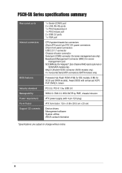
...by PME, chassis intrusion ATX power supply (with enhanced ACPI, PnP, DMI2.0, Green PCI 2.2, PCI-X 1.0a, USB 2.0 WfM 2.0. PSCH-SR Series specifications summary Rear panel ports Internal connectors BIOS features Industry standard Manageability Power requirement Form Factor Support CD contents 1 x Serial (COM1) port 2 x LAN (RJ-45) ...connectors (SATA models only) Firmware Hub Flash ROM (4 Mb for IDE models; 8 Mb for SCSI and SATA models), Award BIOS with 4-pin 12V plug) ATX form factor: 12in x 9.8in (30.5 cm x 25 cm) Device drivers Management software System utilities ASUS contact information...
...by PME, chassis intrusion ATX power supply (with enhanced ACPI, PnP, DMI2.0, Green PCI 2.2, PCI-X 1.0a, USB 2.0 WfM 2.0. PSCH-SR Series specifications summary Rear panel ports Internal connectors BIOS features Industry standard Manageability Power requirement Form Factor Support CD contents 1 x Serial (COM1) port 2 x LAN (RJ-45) ...connectors (SATA models only) Firmware Hub Flash ROM (4 Mb for IDE models; 8 Mb for SCSI and SATA models), Award BIOS with 4-pin 12V plug) ATX form factor: 12in x 9.8in (30.5 cm x 25 cm) Device drivers Management software System utilities ASUS contact information...

PSCH-SR User Manual English Version
Page 24
PCI 2-16 Jumpers 1. LAN_EN2) 2-17 3. SATA/SCSI jumper controller (3-pin SASI_EN1) 2-18 5. Hard disk drive/SCSI LED switch (4-pin J4) 2-20 8. DDR voltage regulator (3-pin J6) 2-21 9. LAN1 port 3. Front panel .... Serial port 6. Serial ROM initialization jumper (3-pin J2) 2-21 Rear panel connectors 1. PS/2 mouse port 2. PS/2 keyboard port 2-22 2-22 2-22 2-22 2-22 2-2223 2-22 Internal connectors 1. 2.2.4 Layout contents Slots Page 1. LAN LED connector (4-pin LAN_LED1) 2-27 9.
PCI 2-16 Jumpers 1. LAN_EN2) 2-17 3. SATA/SCSI jumper controller (3-pin SASI_EN1) 2-18 5. Hard disk drive/SCSI LED switch (4-pin J4) 2-20 8. DDR voltage regulator (3-pin J6) 2-21 9. LAN1 port 3. Front panel .... Serial port 6. Serial ROM initialization jumper (3-pin J2) 2-21 Rear panel connectors 1. PS/2 mouse port 2. PS/2 keyboard port 2-22 2-22 2-22 2-22 2-22 2-2223 2-22 Internal connectors 1. 2.2.4 Layout contents Slots Page 1. LAN LED connector (4-pin LAN_LED1) 2-27 9.

PSCH-SR User Manual English Version
Page 41
...an SMBus host and/or other SMBus devices using the SMBus interface. ® PSCH-SR FPSMB1 1 NC I2C_4_CLK# GND I2C_4_DATA# +5VSB PSCH-SR Front Panel SMBus Connector ASUS PSCH-SR motherboard 2-23 Devices communicate with an SMBus host and/or other SMBus devices using ...PSCH-SR +3.3V GND NC I2C_7_DATA I2C_7_CLK PSCH-SR Power Supply SMBus Header Not all power supply units have SMBus connector for server management. 2. Power supply unit SMBus connector (5-pin PSUSMB1) This connector allows you to connect SMBus (System Management Bus) devices to the power supply unit. 2.7.2 Internal...
...an SMBus host and/or other SMBus devices using the SMBus interface. ® PSCH-SR FPSMB1 1 NC I2C_4_CLK# GND I2C_4_DATA# +5VSB PSCH-SR Front Panel SMBus Connector ASUS PSCH-SR motherboard 2-23 Devices communicate with an SMBus host and/or other SMBus devices using ...PSCH-SR +3.3V GND NC I2C_7_DATA I2C_7_CLK PSCH-SR Power Supply SMBus Header Not all power supply units have SMBus connector for server management. 2. Power supply unit SMBus connector (5-pin PSUSMB1) This connector allows you to connect SMBus (System Management Bus) devices to the power supply unit. 2.7.2 Internal...