

PSCH-SR User Manual English Version
Page 6
..., humidity, and temperature extremes. Operation safety • Before installing the motherboard and adding devices on a stable surface. • If you are connected. Do not place the product in your area. vi If possible, disconnect all cables are correctly connected and the power cables are unplugged. • Seek professional assistance before using , contact your local power company. • If the power supply is set to or...
..., humidity, and temperature extremes. Operation safety • Before installing the motherboard and adding devices on a stable surface. • If you are connected. Do not place the product in your area. vi If possible, disconnect all cables are correctly connected and the power cables are unplugged. • Seek professional assistance before using , contact your local power company. • If the power supply is set to or...
PSCH-SR User Manual English Version
Page 10
... 2 x USB 2.0 ports 1 x VGA port CPU/system/chassis fan connectors 20-pin ATX and 4-pin ATX 12V power connectors 20-pin front panel connectors USB 2.0/1.1 connector Chassis intrusion connector Serial port (COM2) connector (for server management use only) Baseboard Management Connector (BMC) for server management card SODIMM slot for Adaptec® Zero Channel RAID card (optional on SCSI/SATA models only) 68-pin Ultra320 SCSI connector (SCSI models only) 4 x horizontal Serial ATA connectors (SATA models only) Firmware Hub Flash ROM (4 Mb for IDE models; 8 Mb for SCSI and SATA models), Award BIOS...
... 2 x USB 2.0 ports 1 x VGA port CPU/system/chassis fan connectors 20-pin ATX and 4-pin ATX 12V power connectors 20-pin front panel connectors USB 2.0/1.1 connector Chassis intrusion connector Serial port (COM2) connector (for server management use only) Baseboard Management Connector (BMC) for server management card SODIMM slot for Adaptec® Zero Channel RAID card (optional on SCSI/SATA models only) 68-pin Ultra320 SCSI connector (SCSI models only) 4 x horizontal Serial ATA connectors (SATA models only) Firmware Hub Flash ROM (4 Mb for IDE models; 8 Mb for SCSI and SATA models), Award BIOS...
PSCH-SR User Manual English Version
Page 13
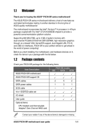
... the Intel® E7210/6300ESB chipset to get ahead in the long line of power computing! Before you for the following items. Item Description ASUS PSCH-SR motherboard PSCH-SR models IDE SATA SCSI ASUS PSCH-SR support CD SATA cables 2 6 2 SATA power cables 1 3 1 SCSI cable • • 4-in-1 IDE/FDD cable set I/O shield User guide Optional items: CPU heatsink and thermal plate Adaptec® Zero Channel RAID card Contact your perfect vehicle to provide a powerful server/workstation platform solution.
... the Intel® E7210/6300ESB chipset to get ahead in the long line of power computing! Before you for the following items. Item Description ASUS PSCH-SR motherboard PSCH-SR models IDE SATA SCSI ASUS PSCH-SR support CD SATA cables 2 6 2 SATA power cables 1 3 1 SCSI cable • • 4-in-1 IDE/FDD cable set I/O shield User guide Optional items: CPU heatsink and thermal plate Adaptec® Zero Channel RAID card Contact your perfect vehicle to provide a powerful server/workstation platform solution.

PSCH-SR User Manual English Version
Page 15
.... ASUS PSCH-SR motherboard user guide 1-3 ASUS server management cards fully conform to the dedicated CSA bus on the Memory Controller Hub (MCH). Single-channel Ultra320 SCSI support (on Motherboard (LOM) applications. The Intel® 82541GI controller utilizes the PCI interface on USB 2.0. Chassis intrusion detection The motherboard supports chassis intrusion monitoring through the Winbond ASIC. USB 2.0 technology The motherboard implements the Universal Serial Bus (USB) 2.0 specification, dramatically increasing the connection speed from SCSI hard disk drives. Take...
.... ASUS PSCH-SR motherboard user guide 1-3 ASUS server management cards fully conform to the dedicated CSA bus on the Memory Controller Hub (MCH). Single-channel Ultra320 SCSI support (on Motherboard (LOM) applications. The Intel® 82541GI controller utilizes the PCI interface on USB 2.0. Chassis intrusion detection The motherboard supports chassis intrusion monitoring through the Winbond ASIC. USB 2.0 technology The motherboard implements the Universal Serial Bus (USB) 2.0 specification, dramatically increasing the connection speed from SCSI hard disk drives. Take...

PSCH-SR User Manual English Version
Page 24
... controller (3-pin VGA_EN1) 2-18 4. Serial port 6. Chassis intrusion connector (4-1 pin CHASSIS1) 2-24 5. LAN LED connector (4-pin LAN_LED1) 2-27 9. Clear RTC RAM (3-pin CLRTC1) 2-19 6. Force BIOS recovery (3-pin J5) 2-20 7. Hard disk drive/SCSI LED switch (4-pin J4) 2-20 8. VGA port 5. Power supply unit SMBus connector (5-pin PSUSMB1) 2-23 2. Serial ATA connectors (7-pin SATA1, SATA2) 2-26 7. ATX power connectors (20-pin ATXPWR1, 4-pin ATX12V1) 2-28 10. Locator connector (6-pin LOCATOR) 2-29 13. LAN_EN2) 2-17 3. LAN1 port 3. USB 2.0 ports...
... controller (3-pin VGA_EN1) 2-18 4. Serial port 6. Chassis intrusion connector (4-1 pin CHASSIS1) 2-24 5. LAN LED connector (4-pin LAN_LED1) 2-27 9. Clear RTC RAM (3-pin CLRTC1) 2-19 6. Force BIOS recovery (3-pin J5) 2-20 7. Hard disk drive/SCSI LED switch (4-pin J4) 2-20 8. VGA port 5. Power supply unit SMBus connector (5-pin PSUSMB1) 2-23 2. Serial ATA connectors (7-pin SATA1, SATA2) 2-26 7. ATX power connectors (20-pin ATXPWR1, 4-pin ATX12V1) 2-28 10. Locator connector (6-pin LOCATOR) 2-29 13. LAN_EN2) 2-17 3. LAN1 port 3. USB 2.0 ports...

PSCH-SR User Manual English Version
Page 29
...; PSCH-SR DIMM_A1 DIMM_A2 DIMM_B1 PSCH-SR 184-Pin DDR DIMM Sockets DIMM_B2 2.4.2 Memory configurations You may install 64 MB, 128 MB, 256 MB, 512 MB, and 1GB DDR DIMMs into the DIMM sockets using the memory configurations in this section. Use any three memory sockets will function in Table 1. • Use the blue DIMM slots first. • In Dual-channel configurations, install only identical (the same type and size) DDR DIMM...
...; PSCH-SR DIMM_A1 DIMM_A2 DIMM_B1 PSCH-SR 184-Pin DDR DIMM Sockets DIMM_B2 2.4.2 Memory configurations You may install 64 MB, 128 MB, 256 MB, 512 MB, and 1GB DDR DIMMs into the DIMM sockets using the memory configurations in this section. Use any three memory sockets will function in Table 1. • Use the blue DIMM slots first. • In Dual-channel configurations, install only identical (the same type and size) DDR DIMM...

PSCH-SR User Manual English Version
Page 32
... expansion card. 1. Secure the card to unplug the power cord before adding or removing expansion cards. Install the software drivers for later use . The motherboard has one 64-bit PCI-X slot and two 32-bit PCI slots. Replace the system cover. 2.5.2 Configuring an expansion card After installing the expansion card, configure it and make the necessary hardware settings for information on the system and change the necessary BIOS settings, if any. Make sure to the chassis with the screw you removed earlier. 6. Align the card connector...
... expansion card. 1. Secure the card to unplug the power cord before adding or removing expansion cards. Install the software drivers for later use . The motherboard has one 64-bit PCI-X slot and two 32-bit PCI slots. Replace the system cover. 2.5.2 Configuring an expansion card After installing the expansion card, configure it and make the necessary hardware settings for information on the system and change the necessary BIOS settings, if any. Make sure to the chassis with the screw you removed earlier. 6. Align the card connector...
PSCH-SR User Manual English Version
Page 33
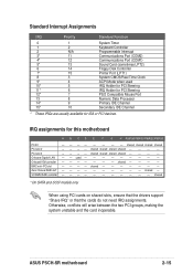
... Controller 2 N/A Programmable Interrupt 3* 11 Communications Port (COM2) 4* 12 Communications Port (COM1) 5* 13 Sound Card (sometimes LPT2) 6 14 Floppy Disk Controller 7* 15 Printer Port (LPT1) 8 3 System CMOS/Real Time Clock 9* 4 ACPI Mode when used - - ------ - - -- - - - Onboard VGA controller - BMC mini-PCI slot - ASUS PSCH-SR motherboard 2-15 shared * On SATA and SCSI models only. shared shared shared shared - - - - - - - B CD E F G H PXIRQ0 PXIRQ1 PXIRQ2 PXIRQ3 shared shared shared shared - - - PCI slot 3 - PCI slot...
... Controller 2 N/A Programmable Interrupt 3* 11 Communications Port (COM2) 4* 12 Communications Port (COM1) 5* 13 Sound Card (sometimes LPT2) 6 14 Floppy Disk Controller 7* 15 Printer Port (LPT1) 8 3 System CMOS/Real Time Clock 9* 4 ACPI Mode when used - - ------ - - -- - - - Onboard VGA controller - BMC mini-PCI slot - ASUS PSCH-SR motherboard 2-15 shared * On SATA and SCSI models only. shared shared shared shared - - - - - - - B CD E F G H PXIRQ0 PXIRQ1 PXIRQ2 PXIRQ3 shared shared shared shared - - - PCI slot 3 - PCI slot...
PSCH-SR User Manual English Version
Page 43
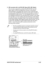
... IDE cable. ® PSCH-SR PSCH-SR IDE Connectors SEC_IDE1 PIN 1 PRI_IDE1 PIN 1 NOTE: Orient the red markings (usually zigzag) on the UltraATA cable connector. You may configure two hard disks to the UltraATA100 master device. one for the primary IDE connector and another for the jumper settings. Refer to PIN 1. 5. BIOS supports specific device bootup. It is removed to match the covered hole on the IDE ribbon cable to the hard disk documentation for...
... IDE cable. ® PSCH-SR PSCH-SR IDE Connectors SEC_IDE1 PIN 1 PRI_IDE1 PIN 1 NOTE: Orient the red markings (usually zigzag) on the UltraATA cable connector. You may configure two hard disks to the UltraATA100 master device. one for the primary IDE connector and another for the jumper settings. Refer to PIN 1. 5. BIOS supports specific device bootup. It is removed to match the covered hole on the IDE ribbon cable to the hard disk documentation for...

PSCH-SR User Manual English Version
Page 44
... RSATA_RXP1 RSATA_RXN1 GND RSATA_TXN1 RSATA_TXP1 GND PSCH-SR SATA Connectors Important notes on Serial ATA • In a legacy operating system (DOS) environment, using the Adaptec HostRAID technology embedded in the Intel® 6300ESB. If you installed Serial ATA hard disk drives and Windows® XP operating system, you can create a RAID 0 or RAID 1 configuration using the Serial ATA connectors will disable the Southbridge support to 150MB/s data transfer rate, faster than the standard...
... RSATA_RXP1 RSATA_RXN1 GND RSATA_TXN1 RSATA_TXP1 GND PSCH-SR SATA Connectors Important notes on Serial ATA • In a legacy operating system (DOS) environment, using the Adaptec HostRAID technology embedded in the Intel® 6300ESB. If you installed Serial ATA hard disk drives and Windows® XP operating system, you can create a RAID 0 or RAID 1 configuration using the Serial ATA connectors will disable the Southbridge support to 150MB/s data transfer rate, faster than the standard...

PSCH-SR User Manual English Version
Page 45
... Adaptec® AIC-8110X RAID controller does not support ATAPI devices such as a RAID set , make sure that you have connected the SATA cable and installed Serial ATA hard disk drives. LAN LED connector (4-pin LAN_LED1) This connector is for the LAN activity LEDs in the system front panel. ® PSCH-SR LAN_LED1 LAN1_LINKACTLED+ LAN1_LINKACTLEDLAN2_LINKACTLEDLAN2_LINKACTLED+ PSCH-SR LANLED Connector ASUS PSCH-SR motherboard 2-27 You cannot enter the SATARaid™ utility and SATA BIOS setup during POST if there are available on SATA models only. Through the...
... Adaptec® AIC-8110X RAID controller does not support ATAPI devices such as a RAID set , make sure that you have connected the SATA cable and installed Serial ATA hard disk drives. LAN LED connector (4-pin LAN_LED1) This connector is for the LAN activity LEDs in the system front panel. ® PSCH-SR LAN_LED1 LAN1_LINKACTLED+ LAN1_LINKACTLEDLAN2_LINKACTLEDLAN2_LINKACTLED+ PSCH-SR LANLED Connector ASUS PSCH-SR motherboard 2-27 You cannot enter the SATARaid™ utility and SATA BIOS setup during POST if there are available on SATA models only. Through the...

PSCH-SR User Manual English Version
Page 53
... failed a power-on the chain)* c. After making all switches are running at the back of the system chassis. 4. Be sure that is working Meaning No error during POST No DRAM installed or detected Video card not found or video card memory bad CPU overheated; Award BIOS beep codes Beep One short beep when displaying logo Long beeps in Chapter 4. 3.1 Starting up . Connect the power cord to the power connector at a lower frequency 7. While the tests are off. 3. Check the jumper settings...
... failed a power-on the chain)* c. After making all switches are running at the back of the system chassis. 4. Be sure that is working Meaning No error during POST No DRAM installed or detected Video card not found or video card memory bad CPU overheated; Award BIOS beep codes Beep One short beep when displaying logo Long beeps in Chapter 4. 3.1 Starting up . Connect the power cord to the power connector at a lower frequency 7. While the tests are off. 3. Check the jumper settings...

PSCH-SR User Manual English Version
Page 72
... motherboard. CPU Configuration Thermal Management Thermal Monitor 1 Select Menu Item Specific Help 4-16 The Thermal Management item is not user-configurable Chapter 4: BIOS Setup CPU L1 & L2 Cache [Enabled] Allows you to display a pop-up menu with the configuration options. Select an item then press to enable or disable the CPU L1 and L2 cache. CPU Configuration CPU L1 & L2 Cache CPU Feature [Enabled] [Press Enter] Select Menu Item Specific Help Disable/Enable CPU L1/ L2 cache. 4.4.2 CPU Configuration This menu shows the CPU configuration settings...
... motherboard. CPU Configuration Thermal Management Thermal Monitor 1 Select Menu Item Specific Help 4-16 The Thermal Management item is not user-configurable Chapter 4: BIOS Setup CPU L1 & L2 Cache [Enabled] Allows you to display a pop-up menu with the configuration options. Select an item then press to enable or disable the CPU L1 and L2 cache. CPU Configuration CPU L1 & L2 Cache CPU Feature [Enabled] [Press Enter] Select Menu Item Specific Help Disable/Enable CPU L1/ L2 cache. 4.4.2 CPU Configuration This menu shows the CPU configuration settings...

PSCH-SR User Manual English Version
Page 74
... command to [Enabled] by caching the display data. Configuration options: [Disabled] [Enabled] Video BIOS Cacheable [Disabled] Allows you to enable or disable the cache function of the system BIOS. System BIOS Cacheable [Enabled] Allows you to enable or disable the cache function of the video BIOS. This item is not user-configurable and set . Chipset Frequency/Voltage Control System BIOS Cacheable Video BIOS Cacheable Init Display First Auto Detect PCI Clk Spread Spectrum [Enabled] [Disabled] [PCI VGA Card] [Enabled] [+/- 0.35%] Select Menu Item Specific Help Press to set...
... command to [Enabled] by caching the display data. Configuration options: [Disabled] [Enabled] Video BIOS Cacheable [Disabled] Allows you to enable or disable the cache function of the system BIOS. System BIOS Cacheable [Enabled] Allows you to enable or disable the cache function of the video BIOS. This item is not user-configurable and set . Chipset Frequency/Voltage Control System BIOS Cacheable Video BIOS Cacheable Init Display First Auto Detect PCI Clk Spread Spectrum [Enabled] [Disabled] [PCI VGA Card] [Enabled] [+/- 0.35%] Select Menu Item Specific Help Press to set...

PSCH-SR User Manual English Version
Page 79
...] ASUS PSCH-SR motherboard 4-23 e. The options for details on the setting of the installed IDE devices into a disk array. Setting to [RAID], this item allows configuration of the On-Chip Serial ATA item. The RAID feature is also disabled. SATA Mode [IDE] When set the SATA Port0 and Serial ATA Port1 modes. Refer to the software installation guide for these items vary depending on RAID configuration. Configuration options: [IDE] [RAID] Serial ATA Port0 Mode [SATA0 Master] Serial ATA Port1 Mode [SATA1...
...] ASUS PSCH-SR motherboard 4-23 e. The options for details on the setting of the installed IDE devices into a disk array. Setting to [RAID], this item allows configuration of the On-Chip Serial ATA item. The RAID feature is also disabled. SATA Mode [IDE] When set the SATA Port0 and Serial ATA Port1 modes. Refer to the software installation guide for these items vary depending on RAID configuration. Configuration options: [IDE] [RAID] Serial ATA Port0 Mode [SATA0 Master] Serial ATA Port1 Mode [SATA1...

PSCH-SR User Manual English Version
Page 80
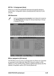
... installed an expansion card that conflicts with the configuration options. Configuration options: [Auto] [Manual] When the item Resources Controlled By is Disabled. Set this problem. Configuration options: [Disabled] [Enabled] 4-24 Chapter 4: BIOS Setup 4.4.6 PCIPnP This menu shows the PCIPnP configuration settings. If you can assign the available IRQ Resources to display a pop-up menu with other devices and cause system boot failure. When set to [Manual], you are using a standard VGA card, leave this item. PCIPnP Reset Configuration Data Resources Controlled...
... installed an expansion card that conflicts with the configuration options. Configuration options: [Auto] [Manual] When the item Resources Controlled By is Disabled. Set this problem. Configuration options: [Disabled] [Enabled] 4-24 Chapter 4: BIOS Setup 4.4.6 PCIPnP This menu shows the PCIPnP configuration settings. If you can assign the available IRQ Resources to display a pop-up menu with other devices and cause system boot failure. When set to [Manual], you are using a standard VGA card, leave this item. PCIPnP Reset Configuration Data Resources Controlled...
PSCH-SR User Manual English Version
Page 81
... device using the interrupt. Configuration options: [Auto] [3] [4] [5] [7] [9] [10] [11] [12] [14] [15] IRQ Resources Set the item Resources Controlled By is set to [Manual] to [Manual]. IRQ-xx assigned to [PCI device] The IRQ Resources sub-menu is activated when the Resources Controlled by parameter is set to enable the item IRQ Resources and assign the interrupts depending on the type of installed PCI device. Setting to [PCI Device] [PCI Device] [PCI Device] [PCI Device] [PCI Device] [PCI Device] [PCI Device] [PCI Device] [PCI Device] [PCI Device] Select Menu Item Specific...
... device using the interrupt. Configuration options: [Auto] [3] [4] [5] [7] [9] [10] [11] [12] [14] [15] IRQ Resources Set the item Resources Controlled By is set to [Manual] to [Manual]. IRQ-xx assigned to [PCI device] The IRQ Resources sub-menu is activated when the Resources Controlled by parameter is set to enable the item IRQ Resources and assign the interrupts depending on the type of installed PCI device. Setting to [PCI Device] [PCI Device] [PCI Device] [PCI Device] [PCI Device] [PCI Device] [PCI Device] [PCI Device] [PCI Device] [PCI Device] Select Menu Item Specific...
PSCH-SR User Manual English Version
Page 82
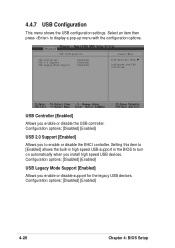
... Configuration USB Controller USB 2.0 Support USB Legacy Mode Support [Enabled] [Enabled] [Enabled] Select Menu Item Specific Help Configures the USB controller. Select an item then press to enable or disable the EHCI controller. Configuration options: [Disabled] [Enabled] USB 2.0 Support [Enabled] Allows you install high speed USB devices. Configuration options: [Disabled] [Enabled] 4-26 Chapter 4: BIOS Setup Setting this item to [Enabled] allows the built-in high speed USB support in the BIOS to turn on automatically when you to display a pop-up menu with the configuration...
... Configuration USB Controller USB 2.0 Support USB Legacy Mode Support [Enabled] [Enabled] [Enabled] Select Menu Item Specific Help Configures the USB controller. Select an item then press to enable or disable the EHCI controller. Configuration options: [Disabled] [Enabled] USB 2.0 Support [Enabled] Allows you install high speed USB devices. Configuration options: [Disabled] [Enabled] 4-26 Chapter 4: BIOS Setup Setting this item to [Enabled] allows the built-in high speed USB support in the BIOS to turn on automatically when you to display a pop-up menu with the configuration...

PSCH-SR User Manual English Version
Page 83
... operating system. ASUS PSCH-SR motherboard 4-27 Select an item then press to set the automatic power saving features. ACPI APIC Support [Enabled] Allows you to change the settings for Operating System. ACPI APIC Support APM Configuration Hardware Configuration [Enabled] Select Menu Item Specific Help Enable/Disable ACPI support for the Advanced Power Management (APM). Select an item then press to enable or disable the ACPI feature on AC Power Loss Video Off Method Video Off In Suspend MODEM Use...
... operating system. ASUS PSCH-SR motherboard 4-27 Select an item then press to set the automatic power saving features. ACPI APIC Support [Enabled] Allows you to change the settings for Operating System. ACPI APIC Support APM Configuration Hardware Configuration [Enabled] Select Menu Item Specific Help Enable/Disable ACPI support for the Advanced Power Management (APM). Select an item then press to enable or disable the ACPI feature on AC Power Loss Video Off Method Video Off In Suspend MODEM Use...

PSCH-SR User Manual English Version
Page 91
...[Enabled] ASUS PSCH-SR motherboard 4-35 Configuration options: [Disabled] [Enabled] Quick Power On Self Test [Enabled] This field speeds up , or to exit this menu. 4.6.5 Boot Settings Configuration Boot Settings Configuration Boot Other Device Quick Power On Self Test Halt On Case Open Warning Boot Up Floppy Seek Boot Up NumLock Status Typematic Rate Setting Typematic Rate (Chars/Sec) Typematic Delay (Msec) [Enabled] [Enabled] [All Errors] [Enabled] [Enabled] [On] [Disabled] 6 250 Select Menu Item Specific Help Select your Boot Device Priority. 4.6.4 CD-ROM Boot Priority CD-ROM Boot...
...[Enabled] ASUS PSCH-SR motherboard 4-35 Configuration options: [Disabled] [Enabled] Quick Power On Self Test [Enabled] This field speeds up , or to exit this menu. 4.6.5 Boot Settings Configuration Boot Settings Configuration Boot Other Device Quick Power On Self Test Halt On Case Open Warning Boot Up Floppy Seek Boot Up NumLock Status Typematic Rate Setting Typematic Rate (Chars/Sec) Typematic Delay (Msec) [Enabled] [Enabled] [All Errors] [Enabled] [Enabled] [On] [Disabled] 6 250 Select Menu Item Specific Help Select your Boot Device Priority. 4.6.4 CD-ROM Boot Priority CD-ROM Boot...


