

PSCH-SR User Manual English Version
Page 4
... 4-13 4.3.4 Secondary IDE Slave 4-13 4.4 Advanced menu 4-14 4.4.1 Advanced BIOS Features 4-15 4.4.2 CPU Configuration 4-16 4.4.3 Memory Configuration 4-17 4.4.4 Chipset 4-18 4.4.5 Onboard Device 4-20 4.4.6 PCIPnP 4-24 4.4.7 USB Configuration 4-26 4.5 Power menu 4-27 4.5.1 APM Configuration 4-27 4.5.2 Hardware Monitor 4-31 4.6 Boot menu 4-33 4.6.1 Boot Device Priority 4-33 4.6.2 Hard Disk Boot Priority 4-34 4.6.3 Removable Device...
... 4-13 4.3.4 Secondary IDE Slave 4-13 4.4 Advanced menu 4-14 4.4.1 Advanced BIOS Features 4-15 4.4.2 CPU Configuration 4-16 4.4.3 Memory Configuration 4-17 4.4.4 Chipset 4-18 4.4.5 Onboard Device 4-20 4.4.6 PCIPnP 4-24 4.4.7 USB Configuration 4-26 4.5 Power menu 4-27 4.5.1 APM Configuration 4-27 4.5.2 Hardware Monitor 4-31 4.6 Boot menu 4-33 4.6.1 Boot Device Priority 4-33 4.6.2 Hard Disk Boot Priority 4-34 4.6.3 Removable Device...
PSCH-SR User Manual English Version
Page 10
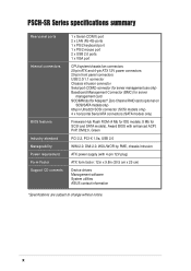
PSCH-SR Series specifications summary Rear panel ports Internal connectors BIOS features Industry standard Manageability Power requirement Form Factor Support CD contents 1 x Serial (COM1) port 2 x LAN (RJ-45) ports 1 x PS/2 keyboard port 1 x PS/2 mouse port 2 x USB 2.0 ports 1 x VGA port CPU/system/chassis fan ...ROM (4 Mb for IDE models; 8 Mb for SCSI and SATA models), Award BIOS with 4-pin 12V plug) ATX form factor: 12in x 9.8in (30.5 cm x 25 cm) Device drivers Management software System utilities ASUS contact information *Specifications are subject to change without notice. DMI ...
PSCH-SR Series specifications summary Rear panel ports Internal connectors BIOS features Industry standard Manageability Power requirement Form Factor Support CD contents 1 x Serial (COM1) port 2 x LAN (RJ-45) ports 1 x PS/2 keyboard port 1 x PS/2 mouse port 2 x USB 2.0 ports 1 x VGA port CPU/system/chassis fan ...ROM (4 Mb for IDE models; 8 Mb for SCSI and SATA models), Award BIOS with 4-pin 12V plug) ATX form factor: 12in x 9.8in (30.5 cm x 25 cm) Device drivers Management software System utilities ASUS contact information *Specifications are subject to change without notice. DMI ...
PSCH-SR User Manual English Version
Page 13
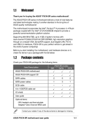
.../workstation platform solution. Before you for the following items. Item Description ASUS PSCH-SR motherboard PSCH-SR models IDE SATA SCSI ASUS PSCH-SR support CD SATA cables 2 6 2 SATA power cables 1 3 1 SCSI cable • • 4-in... 478-pin package coupled with dual-channel PC3200/2700/2100 DDR SDRAM, high-resolution graphics through an onboard VGA, Serial ATA support, dual Gigabit LAN, PCI-X, and USB 2.0 interfaces, PSCH-SR...
.../workstation platform solution. Before you for the following items. Item Description ASUS PSCH-SR motherboard PSCH-SR models IDE SATA SCSI ASUS PSCH-SR support CD SATA cables 2 6 2 SATA power cables 1 3 1 SCSI cable • • 4-in... 478-pin package coupled with dual-channel PC3200/2700/2100 DDR SDRAM, high-resolution graphics through an onboard VGA, Serial ATA support, dual Gigabit LAN, PCI-X, and USB 2.0 interfaces, PSCH-SR...

PSCH-SR User Manual English Version
Page 15
...ASUS PSCH-SR motherboard user guide 1-3 Single-channel Ultra320 SCSI support (on SCSI models only) The Adaptec® AIC-7901X Ultra320 SCSI controller and single-channel SCSI connector are onboard to provide high-speed data transfers to and from the 12Mbps bandwidth on USB 1.1 to a fast 480 Mbps on USB 2.0. ASUS... supports chassis intrusion monitoring through the Winbond ASIC. This reduces the PCI bottlenecks by freeing the PCI bus for the ASUS server management card, managing your server motherboard has never been this easy. Integrated graphics The onboard ATI Rage™ XL...
...ASUS PSCH-SR motherboard user guide 1-3 Single-channel Ultra320 SCSI support (on SCSI models only) The Adaptec® AIC-7901X Ultra320 SCSI controller and single-channel SCSI connector are onboard to provide high-speed data transfers to and from the 12Mbps bandwidth on USB 1.1 to a fast 480 Mbps on USB 2.0. ASUS... supports chassis intrusion monitoring through the Winbond ASIC. This reduces the PCI bottlenecks by freeing the PCI bus for the ASUS server management card, managing your server motherboard has never been this easy. Integrated graphics The onboard ATI Rage™ XL...

PSCH-SR User Manual English Version
Page 24
...2-21 9. LAN2 port 4. Serial connector (10-1 pin COM2 for management use) 2-30 15. Keyboard power (3-pin KBPWR1) 2-17 2. SATA/SCSI jumper controller (3-pin SASI_EN1) 2-18 5. Hard disk drive/SCSI LED switch (4-pin J4) 2-20 8. Serial port 6. Power supply unit...23 3. IDE connectors (40-1 pin PRI_IDE1 [blue], SEC_IDE1 [black) 2-25 6. Integrated graphics controller (3-pin VGA_EN1) 2-18 4. PS/2 mouse port 2. USB 2.0 ports 1 and 2 7. Serial ATA RAID connectors (7-pin SATA_RAID1, 2-27 SATA_RAID2, SATA_RAID3, SATA_RAID4) 8. Ultra320 SCSI connector (68-pin SCSIA1) 2-29...
...2-21 9. LAN2 port 4. Serial connector (10-1 pin COM2 for management use) 2-30 15. Keyboard power (3-pin KBPWR1) 2-17 2. SATA/SCSI jumper controller (3-pin SASI_EN1) 2-18 5. Hard disk drive/SCSI LED switch (4-pin J4) 2-20 8. Serial port 6. Power supply unit...23 3. IDE connectors (40-1 pin PRI_IDE1 [blue], SEC_IDE1 [black) 2-25 6. Integrated graphics controller (3-pin VGA_EN1) 2-18 4. PS/2 mouse port 2. USB 2.0 ports 1 and 2 7. Serial ATA RAID connectors (7-pin SATA_RAID1, 2-27 SATA_RAID2, SATA_RAID3, SATA_RAID4) 8. Ultra320 SCSI connector (68-pin SCSIA1) 2-29...

PSCH-SR User Manual English Version
Page 34
Long PCI cards installed in the PCIX1 and PCI3 slots. 2.5.3 PCI slots The PCI slots support PCI cards such as a LAN card, SCSI card, USB card, and other cards that you install them in the PCI2 slot may interfere with PCI specifications. When installing long PCI cards, it is recommended that comply with the SATA connectors. 2-16 Chapter 2: Hardware information
Long PCI cards installed in the PCIX1 and PCI3 slots. 2.5.3 PCI slots The PCI slots support PCI cards such as a LAN card, SCSI card, USB card, and other cards that you install them in the PCI2 slot may interfere with PCI specifications. When installing long PCI cards, it is recommended that comply with the SATA connectors. 2-16 Chapter 2: Hardware information

PSCH-SR User Manual English Version
Page 40
...Acting SPEED LED Status Description OFF 10Mbps connection ORANGE 100Mbps connection GREEN 1Gbps connection 4. Serial port. Refer to the table below for connecting USB 2.0 devices. 7. This port allows Gigabit connection to a Local Area Network (LAN) through a network hub. VGA port. This 9-...pin COM1 port is for pointing devices or other serial devices. 6. This port connects a VGA display device. 5. USB 2.0 ports 1 and 2. This green 6-pin connector is for a PS/2 mouse. 2. Refer to the table below for the LAN port LED indications. 3....
...Acting SPEED LED Status Description OFF 10Mbps connection ORANGE 100Mbps connection GREEN 1Gbps connection 4. Serial port. Refer to the table below for connecting USB 2.0 devices. 7. This port allows Gigabit connection to a Local Area Network (LAN) through a network hub. VGA port. This 9-...pin COM1 port is for pointing devices or other serial devices. 6. This port connects a VGA display device. 5. USB 2.0 ports 1 and 2. This green 6-pin connector is for a PS/2 mouse. 2. Refer to the table below for the LAN port LED indications. 3....

PSCH-SR User Manual English Version
Page 70
Take caution when changing the settings of the Advanced menu items. Incorrect field values may cause the system to change the settings for the CPU, memory, chipset, and other system devices. Advanced BIOS Features CPU Configuration Memory Configuration Chipset Onboard Device PCIPnP USB Configuration Select Menu Item Specific Help Virus Protection, Boot Sequence... 4-14 Chapter 4: BIOS Setup 4.4 Advanced menu The Advanced menu items allow you to malfunction!
Take caution when changing the settings of the Advanced menu items. Incorrect field values may cause the system to change the settings for the CPU, memory, chipset, and other system devices. Advanced BIOS Features CPU Configuration Memory Configuration Chipset Onboard Device PCIPnP USB Configuration Select Menu Item Specific Help Virus Protection, Boot Sequence... 4-14 Chapter 4: BIOS Setup 4.4 Advanced menu The Advanced menu items allow you to malfunction!
PSCH-SR User Manual English Version
Page 82
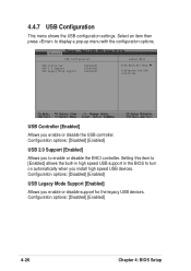
... Mode Support [Enabled] Allows you enable or disable the USB controller. USB Controller [Enabled] Allows you enable or disable support for the legacy USB devices. Select an item then press to enable or disable the EHCI controller. USB Configuration USB Controller USB 2.0 Support USB Legacy Mode Support [Enabled] [Enabled] [Enabled] Select Menu Item Specific Help Configures the...
... Mode Support [Enabled] Allows you enable or disable the USB controller. USB Controller [Enabled] Allows you enable or disable support for the legacy USB devices. Select an item then press to enable or disable the EHCI controller. USB Configuration USB Controller USB 2.0 Support USB Legacy Mode Support [Enabled] [Enabled] [Enabled] Select Menu Item Specific Help Configures the...