

PSCH-SR User Manual English Version
Page 9
PSCH-SR Series specifications summary CPU Chipset Socket 478 for ... (32-bit) ASUS unique features ASUS Q-Fan Technology ASUS Update (continued on the next page) ix Single channel Ultra320 SCSI connector (for RAID 0, RAID 1, RAID 0+1, and RAID 5 configurations using SCSI hard disk drives and the optional Adaptec... x IDE connectors (dual-channel bus master IDE for up to four UltraATA100/66/33 hard disk drives - 2 x Serial ATA connectors (for RAID 0 and RAID 1 configurations using two SATA hard disk drives and Windows® XP) Serial ATA model IDE model storage + Adaptec® AIC-8110X...
PSCH-SR Series specifications summary CPU Chipset Socket 478 for ... (32-bit) ASUS unique features ASUS Q-Fan Technology ASUS Update (continued on the next page) ix Single channel Ultra320 SCSI connector (for RAID 0, RAID 1, RAID 0+1, and RAID 5 configurations using SCSI hard disk drives and the optional Adaptec... x IDE connectors (dual-channel bus master IDE for up to four UltraATA100/66/33 hard disk drives - 2 x Serial ATA connectors (for RAID 0 and RAID 1 configurations using two SATA hard disk drives and Windows® XP) Serial ATA model IDE model storage + Adaptec® AIC-8110X...

PSCH-SR User Manual English Version
Page 14
... (ZCR) solution (optional on SATA and SCSI models only) The motherboard supports the optional Zero Channel RAID card in SODIMM package for two Serial ATA interfaces using Serial ATA150 hard disk drives or Ultra320 SCSI hard disk drives. The motherboard fully supports the ... core frequencies. The processor with lower pin count, reduced voltage requirement, and up to give you six fully-compatible SATA interfaces. The SATA specification allows for various server applications. 1.3 Special features 1.3.1 Product highlights Latest processor technology The motherboard supports the latest Intel...
... (ZCR) solution (optional on SATA and SCSI models only) The motherboard supports the optional Zero Channel RAID card in SODIMM package for two Serial ATA interfaces using Serial ATA150 hard disk drives or Ultra320 SCSI hard disk drives. The motherboard fully supports the ... core frequencies. The processor with lower pin count, reduced voltage requirement, and up to give you six fully-compatible SATA interfaces. The SATA specification allows for various server applications. 1.3 Special features 1.3.1 Product highlights Latest processor technology The motherboard supports the latest Intel...

PSCH-SR User Manual English Version
Page 15
...Ethernet controller allows full-duplex Gigabit performance on LAN on the Memory Controller Hub (MCH). ASUS server management cards fully conform to provide a faster and more efficient networking performance. Integrated ...hard disk drives. USB 2.0 is retained in the CMOS for the ASUS server management card, managing your server motherboard has never been this easy. The Intel® 82541GI controller utilizes the PCI interface on the Southbridge to the IPMI1.5 or 2.0 versions. Server management With the onboard Baseboard Management Connector (BMC) for added protection. ASUS PSCH-SR...
...Ethernet controller allows full-duplex Gigabit performance on LAN on the Memory Controller Hub (MCH). ASUS server management cards fully conform to provide a faster and more efficient networking performance. Integrated ...hard disk drives. USB 2.0 is retained in the CMOS for the ASUS server management card, managing your server motherboard has never been this easy. The Intel® 82541GI controller utilizes the PCI interface on the Southbridge to the IPMI1.5 or 2.0 versions. Server management With the onboard Baseboard Management Connector (BMC) for added protection. ASUS PSCH-SR...

PSCH-SR User Manual English Version
Page 24
... 2-28 10. System panel connector (20-1 pin PANEL) 2-31 2-6 Chapter 2: Hardware information Keyboard power (3-pin KBPWR1) 2-17 2. LAN_EN2) 2-17 3. Hard disk drive/SCSI LED switch (4-pin J4) 2-20 8. DDR voltage regulator (3-pin J6) 2-21 9. USB 2.0 ports 1 and 2 7. Force BIOS recovery (3-pin J5...) 2-27 9. CPU, Front, and Rear Fan connectors 2-30 (3-pin CPU_FAN1/2, FRONT_FAN1/2, REAR_FAN1/2) 14. DDR DIMM 2-11 2. SATA/SCSI jumper controller (3-pin SASI_EN1) 2-18 5. PCI 2-16 Jumpers 1. PS/2 mouse port 2. Power supply unit SMBus connector (5-pin PSUSMB1) 2-23 2....
... 2-28 10. System panel connector (20-1 pin PANEL) 2-31 2-6 Chapter 2: Hardware information Keyboard power (3-pin KBPWR1) 2-17 2. LAN_EN2) 2-17 3. Hard disk drive/SCSI LED switch (4-pin J4) 2-20 8. DDR voltage regulator (3-pin J6) 2-21 9. USB 2.0 ports 1 and 2 7. Force BIOS recovery (3-pin J5...) 2-27 9. CPU, Front, and Rear Fan connectors 2-30 (3-pin CPU_FAN1/2, FRONT_FAN1/2, REAR_FAN1/2) 14. DDR DIMM 2-11 2. SATA/SCSI jumper controller (3-pin SASI_EN1) 2-18 5. PCI 2-16 Jumpers 1. PS/2 mouse port 2. Power supply unit SMBus connector (5-pin PSUSMB1) 2-23 2....

PSCH-SR User Manual English Version
Page 38
6. The HD/SCSI LED is enabled when no jumper cap is placed over the pins. ® PSCH-SR PSCH-SR J4 Jumper 2-20 J4 1 HD/SCSI LED Enable Chapter 2: Hardware information To update the BIOS: 1. Prepare a floppy disk that contains the latest BIOS for the ... you to enable or disable the front panel hard disk drive or SCSI LED. Force BIOS recovery (3-pin J5) This jumper allows you to update or recover the BIOS settings when it gets corrupted or destroyed. ® PSCH-SR J5 12 23 Normal Force BIOS Recovery (Default) PSCH-SR Force BIOS Recovery Setting This jumper allows...
6. The HD/SCSI LED is enabled when no jumper cap is placed over the pins. ® PSCH-SR PSCH-SR J4 Jumper 2-20 J4 1 HD/SCSI LED Enable Chapter 2: Hardware information To update the BIOS: 1. Prepare a floppy disk that contains the latest BIOS for the ... you to enable or disable the front panel hard disk drive or SCSI LED. Force BIOS recovery (3-pin J5) This jumper allows you to update or recover the BIOS settings when it gets corrupted or destroyed. ® PSCH-SR J5 12 23 Normal Force BIOS Recovery (Default) PSCH-SR Force BIOS Recovery Setting This jumper allows...
PSCH-SR User Manual English Version
Page 43
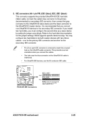
...drive as a slave device by setting its jumper accordingly. Refer to the hard disk documentation for the secondary IDE connector. • Pin 20 on each IDE connector is removed to match the covered hole on the IDE ribbon cable to the secondary IDE connector. BIOS supports specific device bootup. ASUS PSCH-SR... motherboard 2-25 5. IDE connectors (40-1 pin PRI_IDE1 [blue], SEC_IDE1 [black) This connector supports the provided UltraATA100 IDE hard disk ribbon cable.
...drive as a slave device by setting its jumper accordingly. Refer to the hard disk documentation for the secondary IDE connector. • Pin 20 on each IDE connector is removed to match the covered hole on the IDE ribbon cable to the secondary IDE connector. BIOS supports specific device bootup. ASUS PSCH-SR... motherboard 2-25 5. IDE connectors (40-1 pin PRI_IDE1 [blue], SEC_IDE1 [black) This connector supports the provided UltraATA100 IDE hard disk ribbon cable.

PSCH-SR User Manual English Version
Page 44
... GND RSATA_TXN1 RSATA_TXP1 GND PSCH-SR SATA Connectors Important notes on Serial ATA • In a legacy operating system (DOS) environment, using the Adaptec HostRAID technology embedded in the Intel® 6300ESB. Serial ATA connectors (7-pin SATA1, SATA2) These next generation connectors support the thin Serial ATA cables for Serial ATA hard disks. 6. The current...
... GND RSATA_TXN1 RSATA_TXP1 GND PSCH-SR SATA Connectors Important notes on Serial ATA • In a legacy operating system (DOS) environment, using the Adaptec HostRAID technology embedded in the Intel® 6300ESB. Serial ATA connectors (7-pin SATA1, SATA2) These next generation connectors support the thin Serial ATA cables for Serial ATA hard disks. 6. The current...

PSCH-SR User Manual English Version
Page 45
... as a RAID set , make sure that you have connected the SATA cable and installed Serial ATA hard disk drives. LAN LED connector (4-pin LAN_LED1) This connector is for the LAN activity LEDs in the system front panel. ® PSCH-SR LAN_LED1 LAN1_LINKACTLED+ LAN1_LINKACTLEDLAN2_LINKACTLEDLAN2_LINKACTLED+ PSCH-SR LANLED Connector ASUS PSCH-SR motherboard 2-27 You cannot enter the SATARaid™ utility and...
... as a RAID set , make sure that you have connected the SATA cable and installed Serial ATA hard disk drives. LAN LED connector (4-pin LAN_LED1) This connector is for the LAN activity LEDs in the system front panel. ® PSCH-SR LAN_LED1 LAN1_LINKACTLED+ LAN1_LINKACTLEDLAN2_LINKACTLEDLAN2_LINKACTLED+ PSCH-SR LANLED Connector ASUS PSCH-SR motherboard 2-27 You cannot enter the SATARaid™ utility and...

PSCH-SR User Manual English Version
Page 47
...SCSI hard disk drives that you may configure as a RAID set , make sure that you have connected the SCSI cable and installed SCSI devices. 12. The channel can support a maximum of 15 devices as specified by Ultra320 SCSI standards. ® PSCH-SR SCSIA1 68-Pin Ultra320 SCSI Connector 34 1 68 35 PSCH-SR ... (68-pin SCSIA1) The Ultra320 SCSI connector is available on SCSI models only. 11. By default, this connector comes without a jumper. ® PSCH-SR LOCATOR LOCATORLED1+ LOCATORLED1LOCATORBTN#+ GND LOCATORLED2LOCATORLED2+ PSCH-SR LOCATOR Connector ASUS PSCH-SR motherboard 2-29
...SCSI hard disk drives that you may configure as a RAID set , make sure that you have connected the SCSI cable and installed SCSI devices. 12. The channel can support a maximum of 15 devices as specified by Ultra320 SCSI standards. ® PSCH-SR SCSIA1 68-Pin Ultra320 SCSI Connector 34 1 68 35 PSCH-SR ... (68-pin SCSIA1) The Ultra320 SCSI connector is available on SCSI models only. 11. By default, this connector comes without a jumper. ® PSCH-SR LOCATOR LOCATORLED1+ LOCATORLED1LOCATORBTN#+ GND LOCATORLED2LOCATORLED2+ PSCH-SR LOCATOR Connector ASUS PSCH-SR motherboard 2-29

PSCH-SR User Manual English Version
Page 49
...NC POWERLEDMLED+ MLEDNC +5V GND GND SPKROUT ® PSCH-SR PANEL1 HDLED+ HDLEDNMIBTN# GND POWERBTN# GND NC RESETBTN# GND PSCH-SR System Panel Connector • System Power LED (3-pin PLED) This connector is for the system power switch. ASUS PSCH-SR motherboard 2-31 Pressing the power switch turns the system...connector accommodates several system front panel functions. The read or write activities of the hard disk drive connected to the any of IDE connectors cause the hard disk drive LED to the hard disk drive LED. Pressing the power switch for more than 4 seconds when the system ...
...NC POWERLEDMLED+ MLEDNC +5V GND GND SPKROUT ® PSCH-SR PANEL1 HDLED+ HDLEDNMIBTN# GND POWERBTN# GND NC RESETBTN# GND PSCH-SR System Panel Connector • System Power LED (3-pin PLED) This connector is for the system power switch. ASUS PSCH-SR motherboard 2-31 Pressing the power switch turns the system...connector accommodates several system front panel functions. The read or write activities of the hard disk drive connected to the any of IDE connectors cause the hard disk drive LED to the hard disk drive LED. Pressing the power switch for more than 4 seconds when the system ...

PSCH-SR User Manual English Version
Page 66
...Hard Drive..." Primary IDE Master [Auto] Select [Auto] to manually enter the IDE drive parameters. In these cases, select [Manual] to automatically detect an IDE drive. If no drive is installed or if you can manually enter the drive values. appears as the BIOS attempts to the section "Manually detecting an IDE drive." If the drive... the HDD's size, head...on this item to [CHS] if the Primary IDE Master item is set to automatically detect an IDE drive, if the drive is not yet detected. If automatic detection fails, this item is set to [Manual] so you are grayed out when this may ...
...Hard Drive..." Primary IDE Master [Auto] Select [Auto] to manually enter the IDE drive parameters. In these cases, select [Manual] to automatically detect an IDE drive. If no drive is installed or if you can manually enter the drive values. appears as the BIOS attempts to the section "Manually detecting an IDE drive." If the drive... the HDD's size, head...on this item to [CHS] if the Primary IDE Master item is set to automatically detect an IDE drive, if the drive is not yet detected. If automatic detection fails, this item is set to [Manual] so you are grayed out when this may ...

PSCH-SR User Manual English Version
Page 68
...FDISK, to display a pop-up menu. S.M.A.R.T. Cylinder Shows the number of the hard disk read data from the drive documentation, then press . Sector Shows the number of the Primary IDE hard disk drive to set the partition of sectors per track. Transfer Mode Shows the data transfer ...mode if the IDE hard disk drive supports the feature. Capacity [xxxxx MB] Displays the auto-detected hard disk capacity. Otherwise, this item is not userconfigurable. Type in the value from the hard disk. Status Shows the Smart Monitoring, Analysis, and Reporting...
...FDISK, to display a pop-up menu. S.M.A.R.T. Cylinder Shows the number of the hard disk read data from the drive documentation, then press . Sector Shows the number of the Primary IDE hard disk drive to set the partition of sectors per track. Transfer Mode Shows the data transfer ...mode if the IDE hard disk drive supports the feature. Capacity [xxxxx MB] Displays the auto-detected hard disk capacity. Otherwise, this item is not userconfigurable. Type in the value from the hard disk. Status Shows the Smart Monitoring, Analysis, and Reporting...

PSCH-SR User Manual English Version
Page 84
...[NA] [3] [4] [5] [7] [9] [10] [11] 4-28 Chapter 4: BIOS Setup Saving] HDD Power Down [Disabled] Shuts down any IDE hard disk drives in this for monitors without power management or "green" features. Power Management [User Define] Allows you to control the video display card if it ...supports the DPMS feature. [Blank Screen] only blanks the screen. This feature does not affect SCSI hard drives. When set to [Power On], the system turns on or off features. Configuration options: [User Define] [Min. Configuration options: [Disabled] [1 ...
...[NA] [3] [4] [5] [7] [9] [10] [11] 4-28 Chapter 4: BIOS Setup Saving] HDD Power Down [Disabled] Shuts down any IDE hard disk drives in this for monitors without power management or "green" features. Power Management [User Define] Allows you to control the video display card if it ...supports the DPMS feature. [Blank Screen] only blanks the screen. This feature does not affect SCSI hard drives. When set to [Power On], the system turns on or off features. Configuration options: [User Define] [Min. Configuration options: [Disabled] [1 ...