

PSCH-SR User Manual English Version
Page 5
...'s authority to provide reasonable protection against harmful interference in accordance with FCC regulations. Operation is subject to Part 15 of Communications. The use of shielded cables for a Class B digital device, pursuant to the following measures: • Reorient or relocate the receiving antenna. • Increase the separation between the equipment and receiver...
...'s authority to provide reasonable protection against harmful interference in accordance with FCC regulations. Operation is subject to Part 15 of Communications. The use of shielded cables for a Class B digital device, pursuant to the following measures: • Reorient or relocate the receiving antenna. • Increase the separation between the equipment and receiver...

PSCH-SR User Manual English Version
Page 6
...8226; To avoid short circuits, keep paper clips, screws, and staples away from the motherboard, ensure that all cables are correctly connected and the power cables are not damaged. vi If possible, disconnect all the manuals that came with the product, contact a qualified ... Before installing the motherboard and adding devices on a stable surface. • If you add a device. • Before connecting or removing signal cables from connectors, slots, sockets and circuitry. • Avoid dust, humidity, and temperature extremes. If you are using, contact your retailer. Safety ...
...8226; To avoid short circuits, keep paper clips, screws, and staples away from the motherboard, ensure that all cables are correctly connected and the power cables are not damaged. vi If possible, disconnect all the manuals that came with the product, contact a qualified ... Before installing the motherboard and adding devices on a stable surface. • If you add a device. • Before connecting or removing signal cables from connectors, slots, sockets and circuitry. • Avoid dust, humidity, and temperature extremes. If you are using, contact your retailer. Safety ...
PSCH-SR User Manual English Version
Page 13
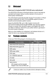
... devices on it another standout in the world of the above items is your PSCH-SR package for buying the ASUS® PSCH-SR series motherboard! Before you for the following items. Item Description ASUS PSCH-SR motherboard PSCH-SR models IDE SATA SCSI ASUS PSCH-SR support CD SATA cables 2 6 2 SATA power cables 1 3 1 SCSI cable • • 4-in 478-pin package coupled with the list below. 1.2 Package contents...
... devices on it another standout in the world of the above items is your PSCH-SR package for buying the ASUS® PSCH-SR series motherboard! Before you for the following items. Item Description ASUS PSCH-SR motherboard PSCH-SR models IDE SATA SCSI ASUS PSCH-SR support CD SATA cables 2 6 2 SATA power cables 1 3 1 SCSI cable • • 4-in 478-pin package coupled with the list below. 1.2 Package contents...

PSCH-SR User Manual English Version
Page 14
... RAID 5 provide a cost-effective, reliable and high-performance server system. 1-2 Chapter 1: Product introduction Zero Channel RAID (ZCR) solution (optional on SATA and SCSI models only) The motherboard supports the optional Zero Channel RAID card in SODIMM package for two Serial ATA interfaces using Serial ATA150 hard..., the motherboard provides a solution that doubles the system memory bandwidth to 6.4 GB/s data transfer rate for thinner, more flexible cables with 1 MB/512 KB L2 cache includes a 800/533/400 MHz system bus and features the Intel Hyper-Threading Technology and...
... RAID 5 provide a cost-effective, reliable and high-performance server system. 1-2 Chapter 1: Product introduction Zero Channel RAID (ZCR) solution (optional on SATA and SCSI models only) The motherboard supports the optional Zero Channel RAID card in SODIMM package for two Serial ATA interfaces using Serial ATA150 hard..., the motherboard provides a solution that doubles the system memory bandwidth to 6.4 GB/s data transfer rate for thinner, more flexible cables with 1 MB/512 KB L2 cache includes a 800/533/400 MHz system bus and features the Intel Hyper-Threading Technology and...

PSCH-SR User Manual English Version
Page 19
... by the edges to a metal object, such as the power supply case, before touching any motherboard component. ® PSCH-SR SB_PWR1 PSCH-SR Onboard LED ON Standby Power OFF Powered Off ASUS PSCH-SR motherboard 2-1 Power LED The motherboard has a green power LED (SB_PWR1). When lit, this LED indicates that the system ... Failure to do so may cause severe damage to static electricity. 3. Whenever you should shut down the system and unplug the power cable before removing or plugging in soft-off mode, a reminder that the ATX power supply is switched off or the power cord is detached...
... by the edges to a metal object, such as the power supply case, before touching any motherboard component. ® PSCH-SR SB_PWR1 PSCH-SR Onboard LED ON Standby Power OFF Powered Off ASUS PSCH-SR motherboard 2-1 Power LED The motherboard has a green power LED (SB_PWR1). When lit, this LED indicates that the system ... Failure to do so may cause severe damage to static electricity. 3. Whenever you should shut down the system and unplug the power cable before removing or plugging in soft-off mode, a reminder that the ATX power supply is switched off or the power cord is detached...

PSCH-SR User Manual English Version
Page 26
... it up to the motherboard. 2-8 Chapter 2: Hardware information Unlock the socket by pressing the lever sideways, then lift it fits in the 4-pin ATX power cable to 90°-100° angle;
... it up to the motherboard. 2-8 Chapter 2: Hardware information Unlock the socket by pressing the lever sideways, then lift it fits in the 4-pin ATX power cable to 90°-100° angle;
PSCH-SR User Manual English Version
Page 43
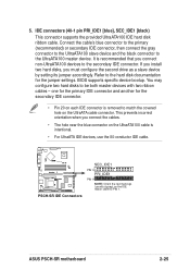
... then connect the gray connector to the UltraATA100 slave device and the black connector to be both master devices with two ribbon cables - ASUS PSCH-SR motherboard 2-25 one for the primary IDE connector and another for the jumper settings. It is intentional. • For UltraATA ...IDE devices, use the 80-conductor IDE cable. ® PSCH-SR PSCH-SR IDE Connectors SEC_IDE1 PIN 1 PRI_IDE1 PIN 1 NOTE: Orient the red markings (usually zigzag) on the UltraATA cable connector. If you install two hard disks, you connect non-UltraATA100 devices to...
... then connect the gray connector to the UltraATA100 slave device and the black connector to be both master devices with two ribbon cables - ASUS PSCH-SR motherboard 2-25 one for the primary IDE connector and another for the jumper settings. It is intentional. • For UltraATA ...IDE devices, use the 80-conductor IDE cable. ® PSCH-SR PSCH-SR IDE Connectors SEC_IDE1 PIN 1 PRI_IDE1 PIN 1 NOTE: Orient the red markings (usually zigzag) on the UltraATA cable connector. If you install two hard disks, you connect non-UltraATA100 devices to...

PSCH-SR User Manual English Version
Page 44
Serial ATA connectors (7-pin SATA1, SATA2) These next generation connectors support the thin Serial ATA cables for Serial ATA hard disks. GND RSATA_RXP2 RSATA_RXN2 GND RSATA_TXN2 RSATA_TXP2 GND ® PSCH-SR SATA2 SATA1 GND RSATA_RXP1 RSATA_RXN1 GND RSATA_TXN1 RSATA_TXP1 GND PSCH-SR SATA Connectors Important notes on Serial ATA • In a legacy operating system (DOS) environment, using...
Serial ATA connectors (7-pin SATA1, SATA2) These next generation connectors support the thin Serial ATA cables for Serial ATA hard disks. GND RSATA_RXP2 RSATA_RXN2 GND RSATA_TXN2 RSATA_TXP2 GND ® PSCH-SR SATA2 SATA1 GND RSATA_RXP1 RSATA_RXN1 GND RSATA_TXN1 RSATA_TXP1 GND PSCH-SR SATA Connectors Important notes on Serial ATA • In a legacy operating system (DOS) environment, using...

PSCH-SR User Manual English Version
Page 45
... ASUS PSCH-SR motherboard 2-27 Through the onboard Adaptec® AIC-8110X RAID controller, you may create a RAID0, RAID1, RAID0+1, or multi-RAID configuration. ® PSCH-SR SATA_RAID4 SATA_RAID3 SATA_RAID2 SATA_RAID1 GND RSATA_TXP1 RSATA_TXN1 GND RSATA_RXN1 RSATA_RXP1 GND PSCH-SR SATA RAID Connectors • If you wish to create a RAID set, make sure that you have connected the SATA cable...
... ASUS PSCH-SR motherboard 2-27 Through the onboard Adaptec® AIC-8110X RAID controller, you may create a RAID0, RAID1, RAID0+1, or multi-RAID configuration. ® PSCH-SR SATA_RAID4 SATA_RAID3 SATA_RAID2 SATA_RAID1 GND RSATA_TXP1 RSATA_TXN1 GND RSATA_RXN1 RSATA_RXP1 GND PSCH-SR SATA RAID Connectors • If you wish to create a RAID set, make sure that you have connected the SATA cable...

PSCH-SR User Manual English Version
Page 46
...motherboard, connect the other end to the floppy disk drive. (Pin 5 is removed to prevent incorrect insertion when using FDD cables with a closed pin 5 hole). ® PSCH-SR FLOPPY1 PIN 1 NOTE: Orient the red markings on the +5-volt standby lead (+5VSB). Floppy disk drive connector (34-1 ...pin FLOPPY1) This connector supports the provided floppy drive ribbon cable. Find the proper orientation and push down firmly until the ...
...motherboard, connect the other end to the floppy disk drive. (Pin 5 is removed to prevent incorrect insertion when using FDD cables with a closed pin 5 hole). ® PSCH-SR FLOPPY1 PIN 1 NOTE: Orient the red markings on the +5-volt standby lead (+5VSB). Floppy disk drive connector (34-1 ...pin FLOPPY1) This connector supports the provided floppy drive ribbon cable. Find the proper orientation and push down firmly until the ...

PSCH-SR User Manual English Version
Page 47
... Adaptec® 7901 SCSI controller. By default, this connector comes without a jumper. ® PSCH-SR LOCATOR LOCATORLED1+ LOCATORLED1LOCATORBTN#+ GND LOCATORLED2LOCATORLED2+ PSCH-SR LOCATOR Connector ASUS PSCH-SR motherboard 2-29 Locator connector (6-pin LOCATOR) This connector controls the locator LEDs in the system front... may configure as specified by Ultra320 SCSI standards. ® PSCH-SR SCSIA1 68-Pin Ultra320 SCSI Connector 34 1 68 35 PSCH-SR Onboard SCSI Connector If you have connected the SCSI cable and installed SCSI devices. 12. Ultra320 SCSI connector (68-pin...
... Adaptec® 7901 SCSI controller. By default, this connector comes without a jumper. ® PSCH-SR LOCATOR LOCATORLED1+ LOCATORLED1LOCATORBTN#+ GND LOCATORLED2LOCATORLED2+ PSCH-SR LOCATOR Connector ASUS PSCH-SR motherboard 2-29 Locator connector (6-pin LOCATOR) This connector controls the locator LEDs in the system front... may configure as specified by Ultra320 SCSI standards. ® PSCH-SR SCSIA1 68-Pin Ultra320 SCSI Connector 34 1 68 35 PSCH-SR Onboard SCSI Connector If you have connected the SCSI cable and installed SCSI devices. 12. Ultra320 SCSI connector (68-pin...

PSCH-SR User Manual English Version
Page 48
... the front fan connectors when using the serial interface. ® PSCH-SR COM2 PIN 1 PSCH-SR Serial COM2 Bracket Since this motherboard support various server configurations. Use the rear fan connectors if you must use a null modem cable to make the connector operational. 2-30 Chapter 2: Hardware information Lack...card using a rackmount configuration. Connect the fan cables to the fan connectors on the motherboard, making sure that the black wire of each cable matches the ground pin of the connector. ® PSCH-SR REAR_FAN1 Speed Power REAR_FAN2 GND CPU_FAN1 CPU_FAN2 Speed...
... the front fan connectors when using the serial interface. ® PSCH-SR COM2 PIN 1 PSCH-SR Serial COM2 Bracket Since this motherboard support various server configurations. Use the rear fan connectors if you must use a null modem cable to make the connector operational. 2-30 Chapter 2: Hardware information Lack...card using a rackmount configuration. Connect the fan cables to the fan connectors on the motherboard, making sure that the black wire of each cable matches the ground pin of the connector. ® PSCH-SR REAR_FAN1 Speed Power REAR_FAN2 GND CPU_FAN1 CPU_FAN2 Speed...