

PSCH-SR User Manual English Version
Page 9
...drives and the optional Adaptec® SODIMM Zero Channel RAID card) Graphics LAN ATI Rage™ XL PCI graphics controller with 8 MB VRAM Intel® 82547GI CSA Gigabit LAN controller Intel® 82541GI Gigabit LAN controller (32-bit) ASUS unique features ASUS Q-Fan Technology ASUS Update (continued on the next page) ix PSCH-SR... (dual-channel bus master IDE for up to four UltraATA100/66/33 hard disk drives - 2 x Serial ATA connectors (for RAID 0 and RAID 1 configurations using two SATA hard disk drives and Windows® XP) Serial ATA model IDE model storage + Adaptec® AIC...
...drives and the optional Adaptec® SODIMM Zero Channel RAID card) Graphics LAN ATI Rage™ XL PCI graphics controller with 8 MB VRAM Intel® 82547GI CSA Gigabit LAN controller Intel® 82541GI Gigabit LAN controller (32-bit) ASUS unique features ASUS Q-Fan Technology ASUS Update (continued on the next page) ix PSCH-SR... (dual-channel bus master IDE for up to four UltraATA100/66/33 hard disk drives - 2 x Serial ATA connectors (for RAID 0 and RAID 1 configurations using two SATA hard disk drives and Windows® XP) Serial ATA model IDE model storage + Adaptec® AIC...

PSCH-SR User Manual English Version
Page 14
... that allow up to 3.4+ GHz core frequencies. The SATA specification allows for two Serial ATA interfaces using Serial ATA150 hard disk drives or Ultra320 SCSI hard disk drives. Zero Channel RAID (ZCR) solution (optional on SATA and SCSI models only) The motherboard supports the optional ...-RAID solution using the Windows® XP operating system. Serial ATA technology The motherboard supports the new Serial ATA technology through the SATA interfaces and the Intel® 6300ESB. The processor with lower pin count, reduced voltage requirement, and up to boost system performance....
... that allow up to 3.4+ GHz core frequencies. The SATA specification allows for two Serial ATA interfaces using Serial ATA150 hard disk drives or Ultra320 SCSI hard disk drives. Zero Channel RAID (ZCR) solution (optional on SATA and SCSI models only) The motherboard supports the optional ...-RAID solution using the Windows® XP operating system. Serial ATA technology The motherboard supports the new Serial ATA technology through the SATA interfaces and the Intel® 6300ESB. The processor with lower pin count, reduced voltage requirement, and up to boost system performance....

PSCH-SR User Manual English Version
Page 15
... (CSA) with the Intel® 82547GI controller that connects to and from the 12Mbps bandwidth on Motherboard (LOM) applications. ASUS PSCH-SR motherboard user guide 1-3 Server management With the onboard Baseboard Management Connector (BMC) for other I/O operations. Chassis intrusion detection The...motherboard implements the Universal Serial Bus (USB) 2.0 specification, dramatically increasing the connection speed from SCSI hard disk drives. ASUS server management cards fully conform to the IPMI1.5 or 2.0 versions. This reduces the PCI bottlenecks by freeing the PCI bus for...
... (CSA) with the Intel® 82547GI controller that connects to and from the 12Mbps bandwidth on Motherboard (LOM) applications. ASUS PSCH-SR motherboard user guide 1-3 Server management With the onboard Baseboard Management Connector (BMC) for other I/O operations. Chassis intrusion detection The...motherboard implements the Universal Serial Bus (USB) 2.0 specification, dramatically increasing the connection speed from SCSI hard disk drives. ASUS server management cards fully conform to the IPMI1.5 or 2.0 versions. This reduces the PCI bottlenecks by freeing the PCI bus for...

PSCH-SR User Manual English Version
Page 24
... (7-pin SATA1, SATA2) 2-26 7. LAN LED connector (4-pin LAN_LED1) 2-27 9. Floppy disk drive connector (34-1 pin FLOPPY1) 2-28 11. DDR DIMM 2-11 2. LAN_EN2) 2-17 3. Hard disk drive/SCSI LED switch (4-pin J4) 2-20 8. VGA port 5. Chassis intrusion connector (4-1 pin CHASSIS1)... SATA_RAID4) 8. CPU, Front, and Rear Fan connectors 2-30 (3-pin CPU_FAN1/2, FRONT_FAN1/2, REAR_FAN1/2) 14. Integrated LAN controllers (3-pin LAN_EN1; SATA/SCSI jumper controller (3-pin SASI_EN1) 2-18 5. Serial ROM initialization jumper (3-pin J2) 2-21 Rear panel connectors 1. LAN1 port 3. Serial...
... (7-pin SATA1, SATA2) 2-26 7. LAN LED connector (4-pin LAN_LED1) 2-27 9. Floppy disk drive connector (34-1 pin FLOPPY1) 2-28 11. DDR DIMM 2-11 2. LAN_EN2) 2-17 3. Hard disk drive/SCSI LED switch (4-pin J4) 2-20 8. VGA port 5. Chassis intrusion connector (4-1 pin CHASSIS1)... SATA_RAID4) 8. CPU, Front, and Rear Fan connectors 2-30 (3-pin CPU_FAN1/2, FRONT_FAN1/2, REAR_FAN1/2) 14. Integrated LAN controllers (3-pin LAN_EN1; SATA/SCSI jumper controller (3-pin SASI_EN1) 2-18 5. Serial ROM initialization jumper (3-pin J2) 2-21 Rear panel connectors 1. LAN1 port 3. Serial...

PSCH-SR User Manual English Version
Page 38
...to pins 1-2. 6. Hard disk drive/SCSI LED switch (4-pin J4) This jumper allows you to update/recover the BIOS quickly. Insert the floppy disk, then turn on the system. 7. The HD/SCSI LED is enabled when no jumper cap is placed over the pins. ® PSCH-SR PSCH-SR J4 Jumper 2-20 J4 1...pin J5) This jumper allows you to update or recover the BIOS settings when it gets corrupted or destroyed. ® PSCH-SR J5 12 23 Normal Force BIOS Recovery (Default) PSCH-SR Force BIOS Recovery Setting This jumper allows you to pins 2-3. 3. Set the jumper to enable or disable the front panel...
...to pins 1-2. 6. Hard disk drive/SCSI LED switch (4-pin J4) This jumper allows you to update/recover the BIOS quickly. Insert the floppy disk, then turn on the system. 7. The HD/SCSI LED is enabled when no jumper cap is placed over the pins. ® PSCH-SR PSCH-SR J4 Jumper 2-20 J4 1...pin J5) This jumper allows you to update or recover the BIOS settings when it gets corrupted or destroyed. ® PSCH-SR J5 12 23 Normal Force BIOS Recovery (Default) PSCH-SR Force BIOS Recovery Setting This jumper allows you to pins 2-3. 3. Set the jumper to enable or disable the front panel...
PSCH-SR User Manual English Version
Page 43
... documentation for the secondary IDE connector. • Pin 20 on the IDE ribbon cable to PIN 1. BIOS supports specific device bootup. ASUS PSCH-SR motherboard 2-25 This prevents incorrect orientation when you connect the cables. • The hole near the blue connector on the UltraATA cable ...disks, you connect non-UltraATA100 devices to match the covered hole on the UltraATA100 cable is recommended that you must configure the second drive as a slave device by setting its jumper accordingly. Connect the cable's blue connector to the primary (recommended) or secondary IDE...
... documentation for the secondary IDE connector. • Pin 20 on the IDE ribbon cable to PIN 1. BIOS supports specific device bootup. ASUS PSCH-SR motherboard 2-25 This prevents incorrect orientation when you connect the cables. • The hole near the blue connector on the UltraATA cable ...disks, you connect non-UltraATA100 devices to match the covered hole on the UltraATA100 cable is recommended that you must configure the second drive as a slave device by setting its jumper accordingly. Connect the cable's blue connector to the primary (recommended) or secondary IDE...

PSCH-SR User Manual English Version
Page 44
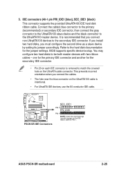
If you installed Serial ATA hard disk drives and Windows® XP operating system, you can create a RAID 0 or RAID 1 configuration using the Serial ATA connectors will disable the Southbridge support to 150MB... generation connectors support the thin Serial ATA cables for Serial ATA hard disks. GND RSATA_RXP2 RSATA_RXN2 GND RSATA_TXN2 RSATA_TXP2 GND ® PSCH-SR SATA2 SATA1 GND RSATA_RXP1 RSATA_RXN1 GND RSATA_TXN1 RSATA_TXP1 GND PSCH-SR SATA Connectors Important notes on Serial ATA • In a legacy operating system (DOS) environment, using the Adaptec HostRAID technology embedded ...
If you installed Serial ATA hard disk drives and Windows® XP operating system, you can create a RAID 0 or RAID 1 configuration using the Serial ATA connectors will disable the Southbridge support to 150MB... generation connectors support the thin Serial ATA cables for Serial ATA hard disks. GND RSATA_RXP2 RSATA_RXN2 GND RSATA_TXN2 RSATA_TXP2 GND ® PSCH-SR SATA2 SATA1 GND RSATA_RXP1 RSATA_RXN1 GND RSATA_TXN1 RSATA_TXP1 GND PSCH-SR SATA Connectors Important notes on Serial ATA • In a legacy operating system (DOS) environment, using the Adaptec HostRAID technology embedded ...

PSCH-SR User Manual English Version
Page 45
...LAN_LED1) This connector is for the LAN activity LEDs in the system front panel. ® PSCH-SR LAN_LED1 LAN1_LINKACTLED+ LAN1_LINKACTLEDLAN2_LINKACTLEDLAN2_LINKACTLED+ PSCH-SR LANLED Connector ASUS PSCH-SR motherboard 2-27 Serial ATA RAID connectors (7-pin SATA_RAID1, SATA_RAID2, SATA_RAID3, SATA_RAID4) The Serial ... PSCH-SR SATA_RAID4 SATA_RAID3 SATA_RAID2 SATA_RAID1 GND RSATA_TXP1 RSATA_TXN1 GND RSATA_RXN1 RSATA_RXP1 GND PSCH-SR SATA RAID Connectors • If you wish to create a RAID set, make sure that you have connected the SATA cable and installed Serial ATA hard disk drives...
...LAN_LED1) This connector is for the LAN activity LEDs in the system front panel. ® PSCH-SR LAN_LED1 LAN1_LINKACTLED+ LAN1_LINKACTLEDLAN2_LINKACTLEDLAN2_LINKACTLED+ PSCH-SR LANLED Connector ASUS PSCH-SR motherboard 2-27 Serial ATA RAID connectors (7-pin SATA_RAID1, SATA_RAID2, SATA_RAID3, SATA_RAID4) The Serial ... PSCH-SR SATA_RAID4 SATA_RAID3 SATA_RAID2 SATA_RAID1 GND RSATA_TXP1 RSATA_TXN1 GND RSATA_RXN1 RSATA_RXP1 GND PSCH-SR SATA RAID Connectors • If you wish to create a RAID set, make sure that you have connected the SATA cable and installed Serial ATA hard disk drives...

PSCH-SR User Manual English Version
Page 46
... +12.0VDC ATXPWR1 Pin 1 ATX12V1 +12V DC GND +12V DC GND +3.3VDC -12.0VDC GND PS_ON# GND GND GND -5.0VDC +5.0VDC +5.0VDC PSCH-SR ATX Power Connectors 10. PSCH-SR Floppy Disk Drive Connector 2-28 Chapter 2: Hardware information Find the proper orientation and push down firmly until the connectors completely fit. In addition to the...
... +12.0VDC ATXPWR1 Pin 1 ATX12V1 +12V DC GND +12V DC GND +3.3VDC -12.0VDC GND PS_ON# GND GND GND -5.0VDC +5.0VDC +5.0VDC PSCH-SR ATX Power Connectors 10. PSCH-SR Floppy Disk Drive Connector 2-28 Chapter 2: Hardware information Find the proper orientation and push down firmly until the connectors completely fit. In addition to the...

PSCH-SR User Manual English Version
Page 47
... SCSI connector is available on SCSI models only. By default, this connector comes without a jumper. ® PSCH-SR LOCATOR LOCATORLED1+ LOCATORLED1LOCATORBTN#+ GND LOCATORLED2LOCATORLED2+ PSCH-SR LOCATOR Connector ASUS PSCH-SR motherboard 2-29 The channel can support a maximum of 15 devices as a RAID set , make sure that... single channel Ultra320 SCSI connector supports SCSI hard disk drives that you may configure as specified by Ultra320 SCSI standards. ® PSCH-SR SCSIA1 68-Pin Ultra320 SCSI Connector 34 1 68 35 PSCH-SR Onboard SCSI Connector If you wish to create a SCSI...
... SCSI connector is available on SCSI models only. By default, this connector comes without a jumper. ® PSCH-SR LOCATOR LOCATORLED1+ LOCATORLED1LOCATORBTN#+ GND LOCATORLED2LOCATORLED2+ PSCH-SR LOCATOR Connector ASUS PSCH-SR motherboard 2-29 The channel can support a maximum of 15 devices as a RAID set , make sure that... single channel Ultra320 SCSI connector supports SCSI hard disk drives that you may configure as specified by Ultra320 SCSI standards. ® PSCH-SR SCSIA1 68-Pin Ultra320 SCSI Connector 34 1 68 35 PSCH-SR Onboard SCSI Connector If you wish to create a SCSI...

PSCH-SR User Manual English Version
Page 49
...) This connector is for rebooting the system without turning off . • Reset Switch (2-pin RESET) This connector is for the system power switch. ASUS PSCH-SR motherboard 2-31 Pressing the power switch turns the system between ON and SLEEP, or ON and SOFT OFF, depending on turns the system off the...system is on the BIOS or OS settings. The read or write activities of the hard disk drive connected to the any of IDE connectors cause the hard disk drive LED to the hard disk drive LED. 15. System panel connector (20-1 pin PANEL) This connector accommodates several system front ...
...) This connector is for rebooting the system without turning off . • Reset Switch (2-pin RESET) This connector is for the system power switch. ASUS PSCH-SR motherboard 2-31 Pressing the power switch turns the system between ON and SLEEP, or ON and SOFT OFF, depending on turns the system off the...system is on the BIOS or OS settings. The read or write activities of the hard disk drive connected to the any of IDE connectors cause the hard disk drive LED to the hard disk drive LED. 15. System panel connector (20-1 pin PANEL) This connector accommodates several system front ...

PSCH-SR User Manual English Version
Page 57
ASUS PSCH-SR motherboard 4-1 c. In the My Computer window, click the 3 1/2 Floppy icon. From the Windows desktop, click Start > My Computer. e. Windows® XP environment a. b. Copy the original (... click Start. 2. Select "Create an MS-DOS Startup Disk" in the future. 4.1.1 Creating a bootable floppy disk 1. d. DOS environment Insert a 1.44 MB floppy disk into the drive. At the DOS prompt, type: format a: /s, then press the key. Insert a new 1.44 MB floppy disk in the floppy disk...
ASUS PSCH-SR motherboard 4-1 c. In the My Computer window, click the 3 1/2 Floppy icon. From the Windows desktop, click Start > My Computer. e. Windows® XP environment a. b. Copy the original (... click Start. 2. Select "Create an MS-DOS Startup Disk" in the future. 4.1.1 Creating a bootable floppy disk 1. d. DOS environment Insert a 1.44 MB floppy disk into the drive. At the DOS prompt, type: format a: /s, then press the key. Insert a new 1.44 MB floppy disk in the floppy disk...

PSCH-SR User Manual English Version
Page 65
...Month: (1 to 12), Day: (1 to 31), Year: (1999 to navigate through them. Use the key to move between the hour, minute, and second fields. ASUS PSCH-SR motherboard 4-9 Refer to section "4.2.1 BIOS menu screen" for month, day, and year are auto-detected. Legacy Diskette A [1.44M, 3.5 in.] Sets the type of ...the basic system information. 4.3 Main menu When you enter the BIOS Setup program, the Main menu screen appears giving you an overview of floppy drive installed. These fields are Hour: (00 to 23), Minute: (00 to 59), Second: (00 to the date that you specify (usually the ...
...Month: (1 to 12), Day: (1 to 31), Year: (1999 to navigate through them. Use the key to move between the hour, minute, and second fields. ASUS PSCH-SR motherboard 4-9 Refer to section "4.2.1 BIOS menu screen" for month, day, and year are auto-detected. Legacy Diskette A [1.44M, 3.5 in.] Sets the type of ...the basic system information. 4.3 Main menu When you enter the BIOS Setup program, the Main menu screen appears giving you an overview of floppy drive installed. These fields are Hour: (00 to 23), Minute: (00 to 59), Second: (00 to the date that you specify (usually the ...

PSCH-SR User Manual English Version
Page 66
... item is successful, the setup BIOS automatically fills in the correct values for the remaining fields on this item to automatically detect an IDE drive, if the drive is too old or too new. appears as the BIOS attempts to the section "Manually detecting an IDE... drive." The default [Auto] allows automatic detection of an IDE drive. If automatic detection fails, this channel. 4.3.1 Primary IDE Master Primary Master Auto-Detection Primary IDE Master Access Mode Capacity Cylinder Head Precomp ...
... item is successful, the setup BIOS automatically fills in the correct values for the remaining fields on this item to automatically detect an IDE drive, if the drive is too old or too new. appears as the BIOS attempts to the section "Manually detecting an IDE... drive." The default [Auto] allows automatic detection of an IDE drive. If automatic detection fails, this channel. 4.3.1 Primary IDE Master Primary Master Auto-Detection Primary IDE Master Access Mode Capacity Cylinder Head Precomp ...

PSCH-SR User Manual English Version
Page 67
The settings Mode 0 to 4 allow successive increase in the value that you obtained from the drive documentation, then press . ASUS PSCH-SR motherboard 4-11 Status [Press Enter] [Manual] [CHS] 0 MB 0 0 0 0 0 [Auto] [Auto] None None Select Menu Item Specific Help Selects the ...type of fixed disk connected to the system. [Manual] lets you wish to manually enter the drive information, set to [Auto], the UDMA ...
The settings Mode 0 to 4 allow successive increase in the value that you obtained from the drive documentation, then press . ASUS PSCH-SR motherboard 4-11 Status [Press Enter] [Manual] [CHS] 0 MB 0 0 0 0 0 [Auto] [Auto] None None Select Menu Item Specific Help Selects the ...type of fixed disk connected to the system. [Manual] lets you wish to manually enter the drive information, set to [Auto], the UDMA ...

PSCH-SR User Manual English Version
Page 68
... is necessary so that you may also highlight the item, then press to partition and format new IDE drives. To enter a value, you can write or read /write heads. Landing Zone Displays the drive's maximum usable capacity as FDISK, to display a pop-up menu. Transfer Mode Shows the data transfer mode... the number of sectors per track. Make sure to "Active." 4-12 Chapter 4: BIOS Setup Cylinder Shows the number of the Primary IDE hard disk drive to set the partition of the hard disk cylinders. Type in the value from the hard disk. S.M.A.R.T. After entering the IDE hard disk...
... is necessary so that you may also highlight the item, then press to partition and format new IDE drives. To enter a value, you can write or read /write heads. Landing Zone Displays the drive's maximum usable capacity as FDISK, to display a pop-up menu. Transfer Mode Shows the data transfer mode... the number of sectors per track. Make sure to "Active." 4-12 Chapter 4: BIOS Setup Cylinder Shows the number of the Primary IDE hard disk drive to set the partition of the hard disk cylinders. Type in the value from the hard disk. S.M.A.R.T. After entering the IDE hard disk...

PSCH-SR User Manual English Version
Page 69
ASUS PSCH-SR motherboard 4-13 4.3.2 Primary IDE Slave When configuring a drive as Primary IDE Slave, refer to section "4.3.1 Primary IDE Master" for the menu item descriptions. 4.3.3 Secondary IDE Master When configuring a drive as Secondary IDE Master, refer to section "4.3.1 Primary IDE Master" for the menu item descriptions. 4.3.4 Secondary IDE Slave When configuring a drive as Secondary IDE Slave, refer to section "4.3.1 Primary IDE Master" for the menu item descriptions.
ASUS PSCH-SR motherboard 4-13 4.3.2 Primary IDE Slave When configuring a drive as Primary IDE Slave, refer to section "4.3.1 Primary IDE Master" for the menu item descriptions. 4.3.3 Secondary IDE Master When configuring a drive as Secondary IDE Master, refer to section "4.3.1 Primary IDE Master" for the menu item descriptions. 4.3.4 Secondary IDE Slave When configuring a drive as Secondary IDE Slave, refer to section "4.3.1 Primary IDE Master" for the menu item descriptions.

PSCH-SR User Manual English Version
Page 78
...c. Use ths option when you installed a legacy operating system like Windows 2000/XP. Max. of 2 IDE drives on each channel. [Enhanced Mode]: Enable both SATA and PATA. Setting to [SATA Only] allows you to install IDE devices on each serial ATA channel for a maximum of six IDE devices on...when you installed a native operating system like MS-DOS, Windows ME/98/NT4.0. of 6 IDE drives are supported. [SATA Only]: SATA is opeating in legacy mode. ***On-Chip Serial ATA Setting*** The SATA Mode and Serial ATA Port0 Mode items are combined. Setting to [Combined Mode] allows you to [...
...c. Use ths option when you installed a legacy operating system like Windows 2000/XP. Max. of 2 IDE drives on each channel. [Enhanced Mode]: Enable both SATA and PATA. Setting to [SATA Only] allows you to install IDE devices on each serial ATA channel for a maximum of six IDE devices on...when you installed a native operating system like MS-DOS, Windows ME/98/NT4.0. of 6 IDE drives are supported. [SATA Only]: SATA is opeating in legacy mode. ***On-Chip Serial ATA Setting*** The SATA Mode and Serial ATA Port0 Mode items are combined. Setting to [Combined Mode] allows you to [...

PSCH-SR User Manual English Version
Page 84
...] This item determines the video off features. Saving] HDD Power Down [Disabled] Shuts down any IDE hard disk drives in this for monitors without power management or "green" features. The Display Power Management System (DPMS) feature allows ... on automatically after a period of inactivity as set the automatic power saving features. Use this user-configurable field. This feature does not affect SCSI hard drives. Configuration options: [NA] [3] [4] [5] [7] [9] [10] [11] 4-28 Chapter 4: BIOS Setup Configuration options: [User Define] [Min. Configuration options: [Disabled] ...
...] This item determines the video off features. Saving] HDD Power Down [Disabled] Shuts down any IDE hard disk drives in this for monitors without power management or "green" features. The Display Power Management System (DPMS) feature allows ... on automatically after a period of inactivity as set the automatic power saving features. Use this user-configurable field. This feature does not affect SCSI hard drives. Configuration options: [NA] [3] [4] [5] [7] [9] [10] [11] 4-28 Chapter 4: BIOS Setup Configuration options: [User Define] [Min. Configuration options: [Disabled] ...

PSCH-SR User Manual English Version
Page 92
... to halt on state for the NumLock. Configuration options: [Disabled] [Enabled] Boot Up Floppy Seek [Enabled] When enabled, the BIOS will seek the floppy disk drive to repeat. Configuration options: [6] [8] [10] [12] [15] [20] [24] [30] Typematic Delay (Msec) [250] Allows you hold a key. Configuration options: [...Disabled] Allows you to select the rate at which character repeats when you to set the delay before key strokes begin to determine whether the drive has 40 or 80 tracks. Typematic Rate (Chars/Sec) [6] Allows you to enable or disable the case open status. Configuration options: ...
... to halt on state for the NumLock. Configuration options: [Disabled] [Enabled] Boot Up Floppy Seek [Enabled] When enabled, the BIOS will seek the floppy disk drive to repeat. Configuration options: [6] [8] [10] [12] [15] [20] [24] [30] Typematic Delay (Msec) [250] Allows you hold a key. Configuration options: [...Disabled] Allows you to select the rate at which character repeats when you to set the delay before key strokes begin to determine whether the drive has 40 or 80 tracks. Typematic Rate (Chars/Sec) [6] Allows you to enable or disable the case open status. Configuration options: ...