

PSCH-SR User Manual English Version
Page 3
Features Contents Notices v Safety information vi About this guide vii PSCH-SR specifications summary ix Chapter 1: Product introduction 1.1 Welcome 1-1 1.2 Package contents 1-1 1.3 Special features 1-2 Chapter 2: Hardware information 2.1 Before you proceed ... 2-14 2.5.1 Installing an expansion card 2-14 2.5.2 Configuring an expansion card 2-14 2.5.3 PCI slots 2-16 2.6 Jumpers 2-17 2.7 Connectors 2-22 2.7.1 Rear panel connectors 2-22 2.7.2 Internal connectors 2-23 Chapter 3: Powering up 3.1 Starting up for the first time 3-1 3.2 Powering off the computer 3-2 3.3.1 Using the OS...
Features Contents Notices v Safety information vi About this guide vii PSCH-SR specifications summary ix Chapter 1: Product introduction 1.1 Welcome 1-1 1.2 Package contents 1-1 1.3 Special features 1-2 Chapter 2: Hardware information 2.1 Before you proceed ... 2-14 2.5.1 Installing an expansion card 2-14 2.5.2 Configuring an expansion card 2-14 2.5.3 PCI slots 2-16 2.6 Jumpers 2-17 2.7 Connectors 2-22 2.7.1 Rear panel connectors 2-22 2.7.2 Internal connectors 2-23 Chapter 3: Powering up 3.1 Starting up for the first time 3-1 3.2 Powering off the computer 3-2 3.3.1 Using the OS...

PSCH-SR User Manual English Version
Page 6
... came with the product, contact a qualified service technician or your dealer immediately. • To avoid short circuits, keep paper clips, screws, and staples away from connectors, slots, sockets and circuitry. • Avoid dust, humidity, and temperature extremes. If you encounter technical problems with the package. • Before using , contact your local...
... came with the product, contact a qualified service technician or your dealer immediately. • To avoid short circuits, keep paper clips, screws, and staples away from connectors, slots, sockets and circuitry. • Avoid dust, humidity, and temperature extremes. If you encounter technical problems with the package. • Before using , contact your local...

PSCH-SR User Manual English Version
Page 7
... lists the hardware setup procedures that you may refer to change system settings through the BIOS Setup menus. Detailed descriptions of the switches, jumpers, and connectors on the motherboard. • Chapter 3: Powering up This chapter describes the power up sequence and gives information on the BIOS beep codes. • Chapter 4: BIOS...
... lists the hardware setup procedures that you may refer to change system settings through the BIOS Setup menus. Detailed descriptions of the switches, jumpers, and connectors on the motherboard. • Chapter 3: Powering up This chapter describes the power up sequence and gives information on the BIOS beep codes. • Chapter 4: BIOS...
PSCH-SR User Manual English Version
Page 9
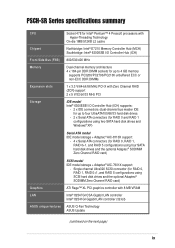
... features ASUS Q-Fan Technology ASUS Update (continued on the next page) ix PSCH-SR Series specifications summary CPU Chipset Socket 478 for Intel® Pentium™ 4 Prescott processors with Hyper-Threading Technology On-die 1MB/512KB L2 cache Northbridge: Intel® E7210 Memory Controller Hub (MCH) Southbridge: Intel® 6300ESB I /O Controller Hub (ICH) supports: - 2 x IDE connectors...
... features ASUS Q-Fan Technology ASUS Update (continued on the next page) ix PSCH-SR Series specifications summary CPU Chipset Socket 478 for Intel® Pentium™ 4 Prescott processors with Hyper-Threading Technology On-die 1MB/512KB L2 cache Northbridge: Intel® E7210 Memory Controller Hub (MCH) Southbridge: Intel® 6300ESB I /O Controller Hub (ICH) supports: - 2 x IDE connectors...

PSCH-SR User Manual English Version
Page 10
... by PME, chassis intrusion ATX power supply (with enhanced ACPI, PnP, DMI2.0, Green PCI 2.2, PCI-X 1.0a, USB 2.0 WfM 2.0. PSCH-SR Series specifications summary Rear panel ports Internal connectors BIOS features Industry standard Manageability Power requirement Form Factor Support CD contents 1 x Serial (COM1) port 2 x LAN (RJ-45) ports... ATA connectors (SATA models only) Firmware Hub Flash ROM (4 Mb for IDE models; 8 Mb for SCSI and SATA models), Award BIOS with 4-pin 12V plug) ATX form factor: 12in x 9.8in (30.5 cm x 25 cm) Device drivers Management software System utilities ASUS contact ...
... by PME, chassis intrusion ATX power supply (with enhanced ACPI, PnP, DMI2.0, Green PCI 2.2, PCI-X 1.0a, USB 2.0 WfM 2.0. PSCH-SR Series specifications summary Rear panel ports Internal connectors BIOS features Industry standard Manageability Power requirement Form Factor Support CD contents 1 x Serial (COM1) port 2 x LAN (RJ-45) ports... ATA connectors (SATA models only) Firmware Hub Flash ROM (4 Mb for IDE models; 8 Mb for SCSI and SATA models), Award BIOS with 4-pin 12V plug) ATX form factor: 12in x 9.8in (30.5 cm x 25 cm) Device drivers Management software System utilities ASUS contact ...
PSCH-SR User Manual English Version
Page 14
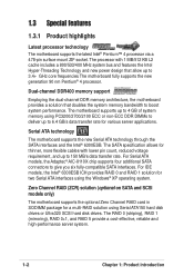
...the SATA interfaces and the Intel® 6300ESB. For Serial ATA models, the Adaptec® AIC-8110X chip supports four additional SATA connectors to 4 GB of system memory using Serial ATA150 hard disk drives or Ultra320 SCSI hard disk drives. Zero Channel RAID (ZCR) ...0 (striping), RAID 1 (mirroring), RAID 0+1, and RAID 5 provide a cost-effective, reliable and high-performance server system. 1-2 Chapter 1: Product introduction For IDE models, the Intel® 6300ESB ICH provides RAID 0 and RAID 1 solution for a multi-RAID solution using PC3200/2700/2100 ECC or non-ECC DDR DIMMs...
...the SATA interfaces and the Intel® 6300ESB. For Serial ATA models, the Adaptec® AIC-8110X chip supports four additional SATA connectors to 4 GB of system memory using Serial ATA150 hard disk drives or Ultra320 SCSI hard disk drives. Zero Channel RAID (ZCR) ...0 (striping), RAID 1 (mirroring), RAID 0+1, and RAID 5 provide a cost-effective, reliable and high-performance server system. 1-2 Chapter 1: Product introduction For IDE models, the Intel® 6300ESB ICH provides RAID 0 and RAID 1 solution for a multi-RAID solution using PC3200/2700/2100 ECC or non-ECC DDR DIMMs...

PSCH-SR User Manual English Version
Page 15
... management card, managing your server motherboard has never been this easy. Server management With the onboard Baseboard Management Connector (BMC) for other I/O operations. ASUS PSCH-SR motherboard user guide 1-3 A chassis intrusion event is backward compatible with USB 1.1. Dual Gigabit LAN solution The Intel®...ASIC. Single-channel Ultra320 SCSI support (on SCSI models only) The Adaptec® AIC-7901X Ultra320 SCSI controller and single-channel SCSI connector are onboard to provide high-speed data transfers to and from the 12Mbps bandwidth on USB 1.1 to a fast 480 Mbps on USB...
... management card, managing your server motherboard has never been this easy. Server management With the onboard Baseboard Management Connector (BMC) for other I/O operations. ASUS PSCH-SR motherboard user guide 1-3 A chassis intrusion event is backward compatible with USB 1.1. Dual Gigabit LAN solution The Intel®...ASIC. Single-channel Ultra320 SCSI support (on SCSI models only) The Adaptec® AIC-7901X Ultra320 SCSI controller and single-channel SCSI connector are onboard to provide high-speed data transfers to and from the 12Mbps bandwidth on USB 1.1 to a fast 480 Mbps on USB...

PSCH-SR User Manual English Version
Page 17
Hardware information It includes details on the switches, jumpers, and connectors on the motherboard. Chapter 2 This chapter describes the hardware setup procedures that you have to perform when installing system components.
Hardware information It includes details on the switches, jumpers, and connectors on the motherboard. Chapter 2 This chapter describes the hardware setup procedures that you have to perform when installing system components.

PSCH-SR User Manual English Version
Page 18
Chapter summary 2.1 Before you proceed 2-1 2.2 Motherboard installation 2-2 2.3 Central Processing Unit (CPU 2-7 2.4 System memory 2-11 2.5 Expansion slots 2-14 2.6 Jumpers 2-17 2.7 Connectors 2-22 ASUS PSCH-SR motherboard
Chapter summary 2.1 Before you proceed 2-1 2.2 Motherboard installation 2-2 2.3 Central Processing Unit (CPU 2-7 2.4 System memory 2-11 2.5 Expansion slots 2-14 2.6 Jumpers 2-17 2.7 Connectors 2-22 ASUS PSCH-SR motherboard
PSCH-SR User Manual English Version
Page 24
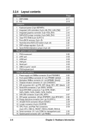
... 2-22 2-22 2-22 2-2223 2-22 Internal connectors 1. LAN1 port 3. Power supply unit SMBus connector (5-pin PSUSMB1) 2-23 2. Serial ATA connectors (7-pin SATA1, SATA2) 2-26 7. Locator connector (6-pin LOCATOR) 2-29 13. USB 2.0 ports 1 and 2 7. IDE connectors (40-1 pin PRI_IDE1 [blue], SEC_IDE1 [black) 2-25 6. Ultra320 SCSI connector (68-pin SCSIA1) 2-29 12. Serial connector (10-1 pin COM2 for management use...
... 2-22 2-22 2-22 2-2223 2-22 Internal connectors 1. LAN1 port 3. Power supply unit SMBus connector (5-pin PSUSMB1) 2-23 2. Serial ATA connectors (7-pin SATA1, SATA2) 2-26 7. Locator connector (6-pin LOCATOR) 2-29 13. USB 2.0 ports 1 and 2 7. IDE connectors (40-1 pin PRI_IDE1 [blue], SEC_IDE1 [black) 2-25 6. Ultra320 SCSI connector (68-pin SCSIA1) 2-29 12. Serial connector (10-1 pin COM2 for management use...
PSCH-SR User Manual English Version
Page 32
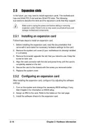
... the bracket opposite the slot that they support. Assign an IRQ to unplug the power cord before adding or removing expansion cards. Align the card connector with the slot and press firmly until the card is already installed in a chassis). 3. Turn on BIOS setup. 2. Secure the card to the chassis with...
... the bracket opposite the slot that they support. Assign an IRQ to unplug the power cord before adding or removing expansion cards. Align the card connector with the slot and press firmly until the card is already installed in a chassis). 3. Turn on BIOS setup. 2. Secure the card to the chassis with...

PSCH-SR User Manual English Version
Page 34
2.5.3 PCI slots The PCI slots support PCI cards such as a LAN card, SCSI card, USB card, and other cards that you install them in the PCI2 slot may interfere with PCI specifications. Long PCI cards installed in the PCIX1 and PCI3 slots. When installing long PCI cards, it is recommended that comply with the SATA connectors. 2-16 Chapter 2: Hardware information
2.5.3 PCI slots The PCI slots support PCI cards such as a LAN card, SCSI card, USB card, and other cards that you install them in the PCI2 slot may interfere with PCI specifications. Long PCI cards installed in the PCIX1 and PCI3 slots. When installing long PCI cards, it is recommended that comply with the SATA connectors. 2-16 Chapter 2: Hardware information

PSCH-SR User Manual English Version
Page 40
... VGA display device. 5. These 4-pin Universal Serial Bus (USB) ports are available for the RJ-45 port LED indications. This purple connector is controlled by the Intel® 82547GI LAN controller. This port is for the LAN port LED indications. VGA port. This port allows ...a Local Area Network (LAN) through a network hub. This port allows Gigabit connection to the table below for connecting USB 2.0 devices. 7. 2.7 Connectors 2.7.1 Rear panel connectors 1 2 7 6 5 4 3 1. This 9-pin COM1 port is controlled by the Intel® 82541GI LAN controller. This green 6-pin...
... VGA display device. 5. These 4-pin Universal Serial Bus (USB) ports are available for the RJ-45 port LED indications. This purple connector is controlled by the Intel® 82547GI LAN controller. This port is for the LAN port LED indications. VGA port. This port allows ...a Local Area Network (LAN) through a network hub. This port allows Gigabit connection to the table below for connecting USB 2.0 devices. 7. 2.7 Connectors 2.7.1 Rear panel connectors 1 2 7 6 5 4 3 1. This 9-pin COM1 port is controlled by the Intel® 82541GI LAN controller. This green 6-pin...

PSCH-SR User Manual English Version
Page 41
Devices communicate with an SMBus host and/or other SMBus devices using the SMBus interface. ® PSCH-SR FPSMB1 1 NC I2C_4_CLK# GND I2C_4_DATA# +5VSB PSCH-SR Front Panel SMBus Connector ASUS PSCH-SR motherboard 2-23 Power supply unit SMBus connector (5-pin PSUSMB1) This connector allows you to connect SMBus (System Management Bus) devices to the power supply unit. Front panel SMBus...
Devices communicate with an SMBus host and/or other SMBus devices using the SMBus interface. ® PSCH-SR FPSMB1 1 NC I2C_4_CLK# GND I2C_4_DATA# +5VSB PSCH-SR Front Panel SMBus Connector ASUS PSCH-SR motherboard 2-23 Power supply unit SMBus connector (5-pin PSUSMB1) This connector allows you to connect SMBus (System Management Bus) devices to the power supply unit. Front panel SMBus...

PSCH-SR User Manual English Version
Page 42
... wish to use the chassis intrusion detection feature, remove the jumper cap from the pins. ® PSCH-SR CHASSIS1 +5VSB CASEOPEN GND (Default) PSCH-SR Chassis Intrusion Connector 2-24 Chapter 2: Hardware information 3. If you remove any chassis component, the sensor triggers and sends ... a chassis intrusion event. Chassis intrusion connector (4-1 pin CHASSIS1) This lead is for a chassis designed with an SMBus host and/or other SMBus devices using the SMBus interface. ® PSCH-SR BPSMB1 1 FAN_PWM I2C_6_CLK# GND I2C_6_DATA# +5V PSCH-SR Backplane SMBus Header 4. By default, ...
... wish to use the chassis intrusion detection feature, remove the jumper cap from the pins. ® PSCH-SR CHASSIS1 +5VSB CASEOPEN GND (Default) PSCH-SR Chassis Intrusion Connector 2-24 Chapter 2: Hardware information 3. If you remove any chassis component, the sensor triggers and sends ... a chassis intrusion event. Chassis intrusion connector (4-1 pin CHASSIS1) This lead is for a chassis designed with an SMBus host and/or other SMBus devices using the SMBus interface. ® PSCH-SR BPSMB1 1 FAN_PWM I2C_6_CLK# GND I2C_6_DATA# +5V PSCH-SR Backplane SMBus Header 4. By default, ...

PSCH-SR User Manual English Version
Page 43
one for the primary IDE connector and another for the jumper settings. ASUS PSCH-SR motherboard 2-25 It is intentional. • For UltraATA IDE devices, use the 80-conductor IDE cable. ® PSCH-SR PSCH-SR IDE Connectors SEC_IDE1 PIN 1 PRI_IDE1 PIN 1 NOTE: Orient the red markings (usually zigzag) on the UltraATA cable connector. Refer to be both master devices with two ribbon cables - You...
one for the primary IDE connector and another for the jumper settings. ASUS PSCH-SR motherboard 2-25 It is intentional. • For UltraATA IDE devices, use the 80-conductor IDE cable. ® PSCH-SR PSCH-SR IDE Connectors SEC_IDE1 PIN 1 PRI_IDE1 PIN 1 NOTE: Orient the red markings (usually zigzag) on the UltraATA cable connector. Refer to be both master devices with two ribbon cables - You...

PSCH-SR User Manual English Version
Page 44
... SATA1 GND RSATA_RXP1 RSATA_RXN1 GND RSATA_TXN1 RSATA_TXP1 GND PSCH-SR SATA Connectors Important notes on Serial ATA • In a legacy operating system (DOS) environment, using the Adaptec HostRAID technology embedded in the Intel® 6300ESB. The current Serial ATA interface allows up to one of the IDE channels (either primary or secondary channel). •...
... SATA1 GND RSATA_RXP1 RSATA_RXN1 GND RSATA_TXN1 RSATA_TXP1 GND PSCH-SR SATA Connectors Important notes on Serial ATA • In a legacy operating system (DOS) environment, using the Adaptec HostRAID technology embedded in the Intel® 6300ESB. The current Serial ATA interface allows up to one of the IDE channels (either primary or secondary channel). •...

PSCH-SR User Manual English Version
Page 45
... for the LAN activity LEDs in the system front panel. ® PSCH-SR LAN_LED1 LAN1_LINKACTLED+ LAN1_LINKACTLEDLAN2_LINKACTLEDLAN2_LINKACTLED+ PSCH-SR LANLED Connector ASUS PSCH-SR motherboard 2-27 These Serial ATA connectors support SATA hard disks that you can configure as CD-ROMs, DVD-ROMs, etc. 8. You cannot enter the SATARaid™ utility and SATA BIOS setup ...
... for the LAN activity LEDs in the system front panel. ® PSCH-SR LAN_LED1 LAN1_LINKACTLED+ LAN1_LINKACTLEDLAN2_LINKACTLEDLAN2_LINKACTLED+ PSCH-SR LANLED Connector ASUS PSCH-SR motherboard 2-27 These Serial ATA connectors support SATA hard disks that you can configure as CD-ROMs, DVD-ROMs, etc. 8. You cannot enter the SATARaid™ utility and SATA BIOS setup ...
PSCH-SR User Manual English Version
Page 46
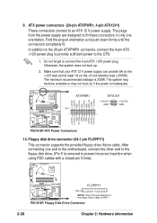
... ribbon cable to connect the 4-pin ATX +12V power plug. Floppy disk drive connector (34-1 pin FLOPPY1) This connector supports the provided floppy drive ribbon cable. The system may become unstable or may not boot up . 2. PSCH-SR Floppy Disk Drive Connector 2-28 Chapter 2: Hardware information Otherwise, the system does not boot up if the...
... ribbon cable to connect the 4-pin ATX +12V power plug. Floppy disk drive connector (34-1 pin FLOPPY1) This connector supports the provided floppy drive ribbon cable. The system may become unstable or may not boot up . 2. PSCH-SR Floppy Disk Drive Connector 2-28 Chapter 2: Hardware information Otherwise, the system does not boot up if the...

PSCH-SR User Manual English Version
Page 47
... drives that you wish to create a SCSI RAID set through the onboard Adaptec® 7901 SCSI controller. By default, this connector comes without a jumper. ® PSCH-SR LOCATOR LOCATORLED1+ LOCATORLED1LOCATORBTN#+ GND LOCATORLED2LOCATORLED2+ PSCH-SR LOCATOR Connector ASUS PSCH-SR motherboard 2-29 The channel can support a maximum of 15 devices as a RAID set , make sure that you may configure as...
... drives that you wish to create a SCSI RAID set through the onboard Adaptec® 7901 SCSI controller. By default, this connector comes without a jumper. ® PSCH-SR LOCATOR LOCATORLED1+ LOCATORLED1LOCATORBTN#+ GND LOCATORLED2LOCATORLED2+ PSCH-SR LOCATOR Connector ASUS PSCH-SR motherboard 2-29 The channel can support a maximum of 15 devices as a RAID set , make sure that you may configure as...
