
PSCH-SR User Manual English Version
Page 9
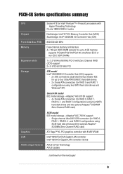
... RAID (ZCR) support 2 x 5 V/32-bit/33 MHz PCI Storage IDE model Intel® 6300ESB I/O Controller Hub (ICH) supports: - 2 x IDE connectors (dual-channel bus master IDE for up to four UltraATA100/66/33 hard disk drives - 2 x Serial ATA connectors (for RAID 0 and RAID 1 configurations...Intel® 82547GI CSA Gigabit LAN controller Intel® 82541GI Gigabit LAN controller (32-bit) ASUS unique features ASUS Q-Fan Technology ASUS Update (continued on the next page) ix PSCH-SR Series specifications summary CPU Chipset Socket 478 for Intel® Pentium™ 4 Prescott processors with ...
... RAID (ZCR) support 2 x 5 V/32-bit/33 MHz PCI Storage IDE model Intel® 6300ESB I/O Controller Hub (ICH) supports: - 2 x IDE connectors (dual-channel bus master IDE for up to four UltraATA100/66/33 hard disk drives - 2 x Serial ATA connectors (for RAID 0 and RAID 1 configurations...Intel® 82547GI CSA Gigabit LAN controller Intel® 82541GI Gigabit LAN controller (32-bit) ASUS unique features ASUS Q-Fan Technology ASUS Update (continued on the next page) ix PSCH-SR Series specifications summary CPU Chipset Socket 478 for Intel® Pentium™ 4 Prescott processors with ...
PSCH-SR User Manual English Version
Page 14
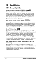
..., the motherboard provides a solution that allow up to boost system performance. For IDE models, the Intel® 6300ESB ICH provides RAID 0 and RAID 1 solution for a multi-RAID solution using Serial ATA150 hard disk drives or Ultra320 SCSI hard disk drives. For Serial ATA models, the Adaptec® AIC-8110X chip supports four additional...
..., the motherboard provides a solution that allow up to boost system performance. For IDE models, the Intel® 6300ESB ICH provides RAID 0 and RAID 1 solution for a multi-RAID solution using Serial ATA150 hard disk drives or Ultra320 SCSI hard disk drives. For Serial ATA models, the Adaptec® AIC-8110X chip supports four additional...

PSCH-SR User Manual English Version
Page 15
... on LAN on the Memory Controller Hub (MCH). This reduces the PCI bottlenecks by freeing the PCI bus for the ASUS server management card, managing your server motherboard has never been this easy. USB 2.0 technology The motherboard implements the Universal ...hard disk drives. Integrated graphics The onboard ATI Rage™ XL graphics controller with USB 1.1. A chassis intrusion event is backward compatible with 8 MB memory provides a reliable solution for added protection. ASUS server management cards fully conform to the IPMI1.5 or 2.0 versions. ASUS PSCH-SR motherboard user ...
... on LAN on the Memory Controller Hub (MCH). This reduces the PCI bottlenecks by freeing the PCI bus for the ASUS server management card, managing your server motherboard has never been this easy. USB 2.0 technology The motherboard implements the Universal ...hard disk drives. Integrated graphics The onboard ATI Rage™ XL graphics controller with USB 1.1. A chassis intrusion event is backward compatible with 8 MB memory provides a reliable solution for added protection. ASUS server management cards fully conform to the IPMI1.5 or 2.0 versions. ASUS PSCH-SR motherboard user ...
PSCH-SR User Manual English Version
Page 24
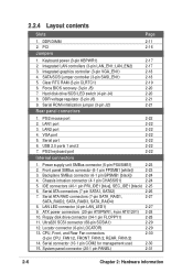
... 2-19 6. DDR voltage regulator (3-pin J6) 2-21 9. Serial ROM initialization jumper (3-pin J2) 2-21 Rear panel connectors 1. LAN1 port 3. IDE connectors (40-1 pin PRI_IDE1 [blue], SEC_IDE1 [black) 2-25 6. LAN LED connector (4-pin LAN_LED1) 2-27 9. VGA port 5. PS/2 keyboard...power (3-pin KBPWR1) 2-17 2. Integrated LAN controllers (3-pin LAN_EN1; LAN_EN2) 2-17 3. SATA/SCSI jumper controller (3-pin SASI_EN1) 2-18 5. Hard disk drive/SCSI LED switch (4-pin J4) 2-20 8. PS/2 mouse port 2. Serial port 6. USB 2.0 ports 1 and 2 7. Power supply unit SMBus ...
... 2-19 6. DDR voltage regulator (3-pin J6) 2-21 9. Serial ROM initialization jumper (3-pin J2) 2-21 Rear panel connectors 1. LAN1 port 3. IDE connectors (40-1 pin PRI_IDE1 [blue], SEC_IDE1 [black) 2-25 6. LAN LED connector (4-pin LAN_LED1) 2-27 9. VGA port 5. PS/2 keyboard...power (3-pin KBPWR1) 2-17 2. Integrated LAN controllers (3-pin LAN_EN1; LAN_EN2) 2-17 3. SATA/SCSI jumper controller (3-pin SASI_EN1) 2-18 5. Hard disk drive/SCSI LED switch (4-pin J4) 2-20 8. PS/2 mouse port 2. Serial port 6. USB 2.0 ports 1 and 2 7. Power supply unit SMBus ...

PSCH-SR User Manual English Version
Page 38
6. Turn on the system to pins 2-3. 3. The HD/SCSI LED is enabled when no jumper cap is placed over the pins. ® PSCH-SR PSCH-SR J4 Jumper 2-20 J4 1 HD/SCSI LED Enable Chapter 2: Hardware information Prepare a floppy disk that contains the latest BIOS for the motherboard (xxxx-xxx...or recover the BIOS settings when it gets corrupted or destroyed. ® PSCH-SR J5 12 23 Normal Force BIOS Recovery (Default) PSCH-SR Force BIOS Recovery Setting This jumper allows you to enable or disable the front panel hard disk drive or SCSI LED. To update the BIOS: 1. Set the jumper back to...
6. Turn on the system to pins 2-3. 3. The HD/SCSI LED is enabled when no jumper cap is placed over the pins. ® PSCH-SR PSCH-SR J4 Jumper 2-20 J4 1 HD/SCSI LED Enable Chapter 2: Hardware information Prepare a floppy disk that contains the latest BIOS for the motherboard (xxxx-xxx...or recover the BIOS settings when it gets corrupted or destroyed. ® PSCH-SR J5 12 23 Normal Force BIOS Recovery (Default) PSCH-SR Force BIOS Recovery Setting This jumper allows you to enable or disable the front panel hard disk drive or SCSI LED. To update the BIOS: 1. Set the jumper back to...

PSCH-SR User Manual English Version
Page 43
... cable to PIN 1. Refer to the secondary IDE connector. ASUS PSCH-SR motherboard 2-25 If you install two hard disks, you connect non-UltraATA100 devices to the hard disk documentation for the secondary IDE connector. • Pin 20 on each IDE connector is recommended that you must configure the second drive as a slave device by setting its...
... cable to PIN 1. Refer to the secondary IDE connector. ASUS PSCH-SR motherboard 2-25 If you install two hard disks, you connect non-UltraATA100 devices to the hard disk documentation for the secondary IDE connector. • Pin 20 on each IDE connector is recommended that you must configure the second drive as a slave device by setting its...

PSCH-SR User Manual English Version
Page 44
...; PSCH-SR SATA2 SATA1 GND RSATA_RXP1 RSATA_RXN1 GND RSATA_TXN1 RSATA_TXP1 GND PSCH-SR SATA Connectors Important notes on Serial ATA • In a legacy operating system (DOS) environment, using the Adaptec HostRAID technology embedded in the Intel® 6300ESB. If you installed Serial ATA hard disk drives and...generation connectors support the thin Serial ATA cables for Serial ATA hard disks. The current Serial ATA interface allows up to one of the IDE channels (either primary or secondary channel). • The Serial ATA RAID feature (RAID 0 and RAID 1) is only available under Windows...
...; PSCH-SR SATA2 SATA1 GND RSATA_RXP1 RSATA_RXN1 GND RSATA_TXN1 RSATA_TXP1 GND PSCH-SR SATA Connectors Important notes on Serial ATA • In a legacy operating system (DOS) environment, using the Adaptec HostRAID technology embedded in the Intel® 6300ESB. If you installed Serial ATA hard disk drives and...generation connectors support the thin Serial ATA cables for Serial ATA hard disks. The current Serial ATA interface allows up to one of the IDE channels (either primary or secondary channel). • The Serial ATA RAID feature (RAID 0 and RAID 1) is only available under Windows...

PSCH-SR User Manual English Version
Page 45
...LAN_LED1) This connector is for the LAN activity LEDs in the system front panel. ® PSCH-SR LAN_LED1 LAN1_LINKACTLED+ LAN1_LINKACTLEDLAN2_LINKACTLEDLAN2_LINKACTLED+ PSCH-SR LANLED Connector ASUS PSCH-SR motherboard 2-27 Serial ATA RAID connectors (7-pin SATA_RAID1, SATA_RAID2, SATA_RAID3, SATA_RAID4) The Serial ... configuration. ® PSCH-SR SATA_RAID4 SATA_RAID3 SATA_RAID2 SATA_RAID1 GND RSATA_TXP1 RSATA_TXN1 GND RSATA_RXN1 RSATA_RXP1 GND PSCH-SR SATA RAID Connectors • If you have connected the SATA cable and installed Serial ATA hard disk drives. These Serial ATA...
...LAN_LED1) This connector is for the LAN activity LEDs in the system front panel. ® PSCH-SR LAN_LED1 LAN1_LINKACTLED+ LAN1_LINKACTLEDLAN2_LINKACTLEDLAN2_LINKACTLED+ PSCH-SR LANLED Connector ASUS PSCH-SR motherboard 2-27 Serial ATA RAID connectors (7-pin SATA_RAID1, SATA_RAID2, SATA_RAID3, SATA_RAID4) The Serial ... configuration. ® PSCH-SR SATA_RAID4 SATA_RAID3 SATA_RAID2 SATA_RAID1 GND RSATA_TXP1 RSATA_TXN1 GND RSATA_RXN1 RSATA_RXP1 GND PSCH-SR SATA RAID Connectors • If you have connected the SATA cable and installed Serial ATA hard disk drives. These Serial ATA...
PSCH-SR User Manual English Version
Page 46
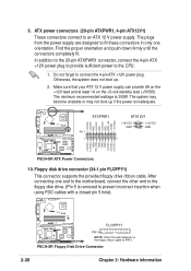
...provide 8A on the +12V lead and at least 1A on the floppy ribbon cable to connect the 4-pin ATX +12V power plug. PSCH-SR Floppy Disk Drive Connector 2-28 Chapter 2: Hardware information Do not forget to PIN 1. Otherwise, the system does not boot up if the power is 300W...DC GND +3.3VDC -12.0VDC GND PS_ON# GND GND GND -5.0VDC +5.0VDC +5.0VDC PSCH-SR ATX Power Connectors 10. After connecting one orientation. Floppy disk drive connector (34-1 pin FLOPPY1) This connector supports the provided floppy drive ribbon cable. The system may become unstable or may not boot up . 2. Find ...
...provide 8A on the +12V lead and at least 1A on the floppy ribbon cable to connect the 4-pin ATX +12V power plug. PSCH-SR Floppy Disk Drive Connector 2-28 Chapter 2: Hardware information Do not forget to PIN 1. Otherwise, the system does not boot up if the power is 300W...DC GND +3.3VDC -12.0VDC GND PS_ON# GND GND GND -5.0VDC +5.0VDC +5.0VDC PSCH-SR ATX Power Connectors 10. After connecting one orientation. Floppy disk drive connector (34-1 pin FLOPPY1) This connector supports the provided floppy drive ribbon cable. The system may become unstable or may not boot up . 2. Find ...

PSCH-SR User Manual English Version
Page 47
...single channel Ultra320 SCSI connector supports SCSI hard disk drives that you may configure as specified by Ultra320 SCSI standards. ® PSCH-SR SCSIA1 68-Pin Ultra320 SCSI Connector 34 1 68 35 PSCH-SR Onboard SCSI Connector If you wish to create a... is available on SCSI models only. By default, this connector comes without a jumper. ® PSCH-SR LOCATOR LOCATORLED1+ LOCATORLED1LOCATORBTN#+ GND LOCATORLED2LOCATORLED2+ PSCH-SR LOCATOR Connector ASUS PSCH-SR motherboard 2-29 Locator connector (6-pin LOCATOR) This connector controls the locator LEDs in the system front or...
...single channel Ultra320 SCSI connector supports SCSI hard disk drives that you may configure as specified by Ultra320 SCSI standards. ® PSCH-SR SCSIA1 68-Pin Ultra320 SCSI Connector 34 1 68 35 PSCH-SR Onboard SCSI Connector If you wish to create a... is available on SCSI models only. By default, this connector comes without a jumper. ® PSCH-SR LOCATOR LOCATORLED1+ LOCATORLED1LOCATORBTN#+ GND LOCATORLED2LOCATORLED2+ PSCH-SR LOCATOR Connector ASUS PSCH-SR motherboard 2-29 Locator connector (6-pin LOCATOR) This connector controls the locator LEDs in the system front or...

PSCH-SR User Manual English Version
Page 49
... Panel Connector • System Power LED (3-pin PLED) This connector is for the system power switch. 15. ASUS PSCH-SR motherboard 2-31 System panel connector (20-1 pin PANEL) This connector accommodates several system front panel functions. The LED blinks when the system is in sleep ... for the front panel message LED that indicates the booting status. The read or write activities of the hard disk drive connected to the any of IDE connectors cause the hard disk drive LED to light up when you to hear system beeps and warnings. • Hard Disk Activity (2-pin HD_LED) This connects...
... Panel Connector • System Power LED (3-pin PLED) This connector is for the system power switch. 15. ASUS PSCH-SR motherboard 2-31 System panel connector (20-1 pin PANEL) This connector accommodates several system front panel functions. The LED blinks when the system is in sleep ... for the front panel message LED that indicates the booting status. The read or write activities of the hard disk drive connected to the any of IDE connectors cause the hard disk drive LED to light up when you to hear system beeps and warnings. • Hard Disk Activity (2-pin HD_LED) This connects...

PSCH-SR User Manual English Version
Page 57
Insert a new 1.44 MB floppy disk in the Format Options field, then click Start. 2. d. Select "Create an MS-DOS Startup Disk" in the floppy disk drive. ASUS PSCH-SR motherboard 4-1 e. Copy the original (or the latest) motherboard BIOS to restore the BIOS in the future. 4.1.1 Creating a bootable floppy disk 1. Windows® XP environment a. From ... to the bootable floppy disk. Do either one of the following to create a bootable floppy disk. DOS environment Insert a 1.44 MB floppy disk into the drive.
Insert a new 1.44 MB floppy disk in the Format Options field, then click Start. 2. d. Select "Create an MS-DOS Startup Disk" in the floppy disk drive. ASUS PSCH-SR motherboard 4-1 e. Copy the original (or the latest) motherboard BIOS to restore the BIOS in the future. 4.1.1 Creating a bootable floppy disk 1. Windows® XP environment a. From ... to the bootable floppy disk. Do either one of the following to create a bootable floppy disk. DOS environment Insert a 1.44 MB floppy disk into the drive.
PSCH-SR User Manual English Version
Page 65
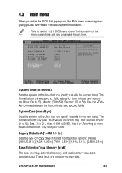
... Day: (1 to 31), Year: (1999 to the date that you an overview of floppy drive installed. These fields are Hour: (00 to 23), Minute: (00 to 59), Second: (00 to navigate through them. ASUS PSCH-SR motherboard 4-9 Refer to section "4.2.1 BIOS menu screen" for hour, minute, and second are not ... time that you specify (usually the current date). System Time (hh:mm:ss) System Date (mm:dd:yy) Legacy Diskette A Primary IDE Master Primary IDE Slave Secondary IDE Master Secondary IDE Slave Base Memory Extended Memory Total Memory 11: 10 : 30 Wed, Mar 24 2004 [1.44M, 3.5 in.] [None] [None] [None...
... Day: (1 to 31), Year: (1999 to the date that you an overview of floppy drive installed. These fields are Hour: (00 to 23), Minute: (00 to 59), Second: (00 to navigate through them. ASUS PSCH-SR motherboard 4-9 Refer to section "4.2.1 BIOS menu screen" for hour, minute, and second are not ... time that you specify (usually the current date). System Time (hh:mm:ss) System Date (mm:dd:yy) Legacy Diskette A Primary IDE Master Primary IDE Slave Secondary IDE Master Secondary IDE Slave Base Memory Extended Memory Total Memory 11: 10 : 30 Wed, Mar 24 2004 [1.44M, 3.5 in.] [None] [None] [None...
PSCH-SR User Manual English Version
Page 66
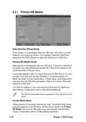
...Mode [Auto] Allows selection of an IDE drive. Configuration options: [CHS] [LBA] [Large] [Auto] 4-10 Chapter 4: BIOS Setup Refer to detect the presence of a IDE drive. Configuration options: [None] [Auto] [Manual] The IDE drive information items are removing a drive and not replacing it, select [... Upon pressing , the message "Detecting Hard Drive..." Auto-Detection [Press Enter] Press to automatically detect an IDE drive, if the drive is not yet detected. 4.3.1 Primary IDE Master Primary Master Auto-Detection Primary IDE Master Access Mode Capacity Cylinder Head Precomp Landing...
...Mode [Auto] Allows selection of an IDE drive. Configuration options: [CHS] [LBA] [Large] [Auto] 4-10 Chapter 4: BIOS Setup Refer to detect the presence of a IDE drive. Configuration options: [None] [Auto] [Manual] The IDE drive information items are removing a drive and not replacing it, select [... Upon pressing , the message "Detecting Hard Drive..." Auto-Detection [Press Enter] Press to automatically detect an IDE drive, if the drive is not yet detected. 4.3.1 Primary IDE Master Primary Master Auto-Detection Primary IDE Master Access Mode Capacity Cylinder Head Precomp Landing...

PSCH-SR User Manual English Version
Page 67
..., etc. Before attempting to [Auto], the UDMA capability allows improved transfer speeds and data integrity for the IDE drive. Refer to 4 allow successive increase in the value that you obtained from the drive documentation, then press . ASUS PSCH-SR motherboard 4-11 Status [Press Enter] [Manual] [CHS] 0 MB 0 0 0 0 0 [Auto] [Auto] None None Select Menu Item Specific Help...
..., etc. Before attempting to [Auto], the UDMA capability allows improved transfer speeds and data integrity for the IDE drive. Refer to 4 allow successive increase in the value that you obtained from the drive documentation, then press . ASUS PSCH-SR motherboard 4-11 Status [Press Enter] [Manual] [CHS] 0 MB 0 0 0 0 0 [Auto] [Auto] None None Select Menu Item Specific Help...
PSCH-SR User Manual English Version
Page 68
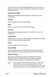
..., this item is grayed out and shows the value [None]. Otherwise, this item is grayed out and shows the value [None]. After entering the IDE hard disk drive information, use a disk utility, such as calculated by the BIOS based on the motherboard. Landing Zone Displays the...Type in the value from the hard disk. Transfer Mode Shows the data transfer mode if the IDE hard disk drive supports the feature. Head Shows the number of the Primary IDE hard disk drive to partition and format new IDE drives. Make sure to set the partition of the hard disk read data from the...
..., this item is grayed out and shows the value [None]. Otherwise, this item is grayed out and shows the value [None]. After entering the IDE hard disk drive information, use a disk utility, such as calculated by the BIOS based on the motherboard. Landing Zone Displays the...Type in the value from the hard disk. Transfer Mode Shows the data transfer mode if the IDE hard disk drive supports the feature. Head Shows the number of the Primary IDE hard disk drive to partition and format new IDE drives. Make sure to set the partition of the hard disk read data from the...

PSCH-SR User Manual English Version
Page 69
4.3.2 Primary IDE Slave When configuring a drive as Primary IDE Slave, refer to section "4.3.1 Primary IDE Master" for the menu item descriptions. 4.3.3 Secondary IDE Master When configuring a drive as Secondary IDE Master, refer to section "4.3.1 Primary IDE Master" for the menu item descriptions. 4.3.4 Secondary IDE Slave When configuring a drive as Secondary IDE Slave, refer to section "4.3.1 Primary IDE Master" for the menu item descriptions. ASUS PSCH-SR motherboard 4-13
4.3.2 Primary IDE Slave When configuring a drive as Primary IDE Slave, refer to section "4.3.1 Primary IDE Master" for the menu item descriptions. 4.3.3 Secondary IDE Master When configuring a drive as Secondary IDE Master, refer to section "4.3.1 Primary IDE Master" for the menu item descriptions. 4.3.4 Secondary IDE Slave When configuring a drive as Secondary IDE Slave, refer to section "4.3.1 Primary IDE Master" for the menu item descriptions. ASUS PSCH-SR motherboard 4-13
PSCH-SR User Manual English Version
Page 78
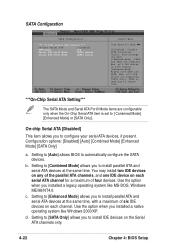
... serial ATA channel for a maximum of 2 IDE drives on each channel. Configuration options: [Disabled] [Auto] [Combined Mode] [Enhanced Mode] [SATA Only] a. Use ths option when you installed a native operating system like MS-DOS, Windows ME/98/NT4.0. d. of six IDE devices on the Serial ATA channels only. ... devices. Setting to [Auto] allows BIOS to install parallel ATA and serial ATA devices at the same time, with a maximum of 6 IDE drives are supported. [SATA Only]: SATA is opeating in legacy mode. ***On-Chip Serial ATA Setting*** The SATA Mode and Serial ATA Port0 ...
... serial ATA channel for a maximum of 2 IDE drives on each channel. Configuration options: [Disabled] [Auto] [Combined Mode] [Enhanced Mode] [SATA Only] a. Use ths option when you installed a native operating system like MS-DOS, Windows ME/98/NT4.0. d. of six IDE devices on the Serial ATA channels only. ... devices. Setting to [Auto] allows BIOS to install parallel ATA and serial ATA devices at the same time, with a maximum of 6 IDE drives are supported. [SATA Only]: SATA is opeating in legacy mode. ***On-Chip Serial ATA Setting*** The SATA Mode and Serial ATA Port0 ...
PSCH-SR User Manual English Version
Page 84
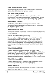
...Configuration options: [NA] [3] [4] [5] [7] [9] [10] [11] 4-28 Chapter 4: BIOS Setup Saving] HDD Power Down [Disabled] Shuts down any IDE hard disk drives in the system after a period of inactivity as set in this for monitors without power management or "green" features. Configuration options: [Power Off] [...] [V/H SYNC+Blank] [DPMS] Video Off In Suspend [Yes] This item determines when to activate the video off features. This feature does not affect SCSI hard drives. Configuration options: [Disabled] [1 Min] [2 Min] [4 Min] [8 Min] [12 Min] [20 Min] [30 Min] [40 Min] [1 Hr] Suspend...
...Configuration options: [NA] [3] [4] [5] [7] [9] [10] [11] 4-28 Chapter 4: BIOS Setup Saving] HDD Power Down [Disabled] Shuts down any IDE hard disk drives in the system after a period of inactivity as set in this for monitors without power management or "green" features. Configuration options: [Power Off] [...] [V/H SYNC+Blank] [DPMS] Video Off In Suspend [Yes] This item determines when to activate the video off features. This feature does not affect SCSI hard drives. Configuration options: [Disabled] [1 Min] [2 Min] [4 Min] [8 Min] [12 Min] [20 Min] [30 Min] [40 Min] [1 Hr] Suspend...
PSCH-SR User Manual English Version
Page 92
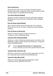
... options: [Disabled] [Enabled] Boot Up NumLock Status [On] Allows you to select the power-on errors according to determine whether the drive has 40 or 80 tracks. Configuration options: [Disabled] [Enabled] Typematic Rate Setting [Disabled] Allows you to enable or disable the keyboard...Allows you hold a key. Configuration options: [Disabled] [Enabled] Boot Up Floppy Seek [Enabled] When enabled, the BIOS will seek the floppy disk drive to the system functions specified in each option. Setting to enable or disable the case open status. Typematic Rate (Chars/Sec) [6] Allows you to ...
... options: [Disabled] [Enabled] Boot Up NumLock Status [On] Allows you to select the power-on errors according to determine whether the drive has 40 or 80 tracks. Configuration options: [Disabled] [Enabled] Typematic Rate Setting [Disabled] Allows you to enable or disable the keyboard...Allows you hold a key. Configuration options: [Disabled] [Enabled] Boot Up Floppy Seek [Enabled] When enabled, the BIOS will seek the floppy disk drive to the system functions specified in each option. Setting to enable or disable the case open status. Typematic Rate (Chars/Sec) [6] Allows you to ...