User Guide
Page 19
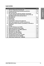
...(2-pin T_SENSOR) Page 1-12 1-19 1-4 1-18 1-5 1-10 1-9 1-22 1-16 1-14 1-12 1-11 1-20 1-17 1-21 1-23 1-24 1-15 1-21 1-24 ASUS PRIME Z370-A Series 1-3 CPU, CPU optional, M.2, AIO pump, extension, and chassis fan connectors (4-pin CPU_FAN; 4-pin CPU_OPT; 4-pin M.2_FAN; 4-pin AIO_PUMP; 5-pin EXT_FAN; 4-pin...pin RGB_HEADER) 17. System panel connector (20-3 pin PANEL) 14. USB1112) 15. Serial port connector (10-1 pin COM) 18. button 7. Clear RTC RAM jumper (2-pin CLRTC) 13. M.2_2(Socket 3)) 9. M.2 sockets (M.2_1(Socket 3); USB 2.0 connectors (10-1 pin USB910; Power-on button 8. Chapter 1...
...(2-pin T_SENSOR) Page 1-12 1-19 1-4 1-18 1-5 1-10 1-9 1-22 1-16 1-14 1-12 1-11 1-20 1-17 1-21 1-23 1-24 1-15 1-21 1-24 ASUS PRIME Z370-A Series 1-3 CPU, CPU optional, M.2, AIO pump, extension, and chassis fan connectors (4-pin CPU_FAN; 4-pin CPU_OPT; 4-pin M.2_FAN; 4-pin AIO_PUMP; 5-pin EXT_FAN; 4-pin...pin RGB_HEADER) 17. System panel connector (20-3 pin PANEL) 14. USB1112) 15. Serial port connector (10-1 pin COM) 18. button 7. Clear RTC RAM jumper (2-pin CLRTC) 13. M.2_2(Socket 3)) 9. M.2 sockets (M.2_1(Socket 3); USB 2.0 connectors (10-1 pin USB910; Power-on button 8. Chapter 1...

User Guide
Page 27
... the power cord and turn off is required to re-enter data. function. 1.1.7 Jumpers and holes 1. Chapter 1 To erase the RTC RAM: 1. ASUS PRIME Z370-A Series 1-11 Except when clearing the RTC RAM, never place a metal object or jumper cap on the power supply or unplug and plug the power cord before rebooting the system...
... the power cord and turn off is required to re-enter data. function. 1.1.7 Jumpers and holes 1. Chapter 1 To erase the RTC RAM: 1. ASUS PRIME Z370-A Series 1-11 Except when clearing the RTC RAM, never place a metal object or jumper cap on the power supply or unplug and plug the power cord before rebooting the system...
User Guide
Page 60
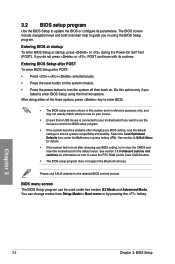
See section 3.10 Exit Menu for information on . Chapter 3 3-2 Chapter 3: BIOS Setup Please visit ASUS website for reference purposes only, and may not exactly match what you see on your screen. • Ensure that a USB mouse is connected to your ... the reset button on the system chassis. • Press the power button to turn the system off then back on how to erase the RTC RAM via the Clear CMOS button. • The BIOS setup program does not support the Bluetooth devices. Select the Load Optimized Defaults item under two modes...
See section 3.10 Exit Menu for information on . Chapter 3 3-2 Chapter 3: BIOS Setup Please visit ASUS website for reference purposes only, and may not exactly match what you see on your screen. • Ensure that a USB mouse is connected to your ... the reset button on the system chassis. • Press the power button to turn the system off then back on how to erase the RTC RAM via the Clear CMOS button. • The BIOS setup program does not support the Bluetooth devices. Select the Load Optimized Defaults item under two modes...
User Guide
Page 72
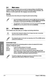
See section 1.1.6 Onboard buttons and switches for information on how to erase the RTC RAM via the Clear CMOS button. • The Administrator or User Password items on the CPU and DIMM model you to configure overclocking-related items. Be ... default [Not Installed]. Chapter 3 3-14 Chapter 3: BIOS Setup After you set the profiles supported by your BIOS password, erase the CMOS Real Time Clock (RTC) RAM to clear the BIOS password. Security The Security menu items allow you installed on the motherboard. Ai Overclock Tuner Allows you enter the Advanced Mode...
See section 1.1.6 Onboard buttons and switches for information on how to erase the RTC RAM via the Clear CMOS button. • The Administrator or User Password items on the CPU and DIMM model you to configure overclocking-related items. Be ... default [Not Installed]. Chapter 3 3-14 Chapter 3: BIOS Setup After you set the profiles supported by your BIOS password, erase the CMOS Real Time Clock (RTC) RAM to clear the BIOS password. Security The Security menu items allow you installed on the motherboard. Ai Overclock Tuner Allows you enter the Advanced Mode...


