
Users Manual English
Page 1
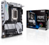
Motherboard PRIME TRX40PRO S
Motherboard PRIME TRX40PRO S

Users Manual English
Page 3
...information...vi About this guide...vii PRIME TRX40-PRO S specifications summary ix Package contents...xiv Installation tools and components xv Chapter 1: Product Introduction 1.1 Before you proceed 1-1 1.2 Motherboard layout 1-2 1.3 Central Processing ... connectors 1-13 Chapter 2: Basic Installation 2.1 Building your PC system 2-1 2.1.1 CPU installation 2-1 2.1.2 Cooling system installation 2-4 2.1.3 Motherboard installation 2-5 2.1.4 DIMM installation 2-6 2.1.5 ATX power connection 2-7 2.1.6 SATA device connection 2-8 2.1.7 Front I/O connector 2-9 2.1.8 Expansion...
...information...vi About this guide...vii PRIME TRX40-PRO S specifications summary ix Package contents...xiv Installation tools and components xv Chapter 1: Product Introduction 1.1 Before you proceed 1-1 1.2 Motherboard layout 1-2 1.3 Central Processing ... connectors 1-13 Chapter 2: Basic Installation 2.1 Building your PC system 2-1 2.1.1 CPU installation 2-1 2.1.2 Cooling system installation 2-4 2.1.3 Motherboard installation 2-5 2.1.4 DIMM installation 2-6 2.1.5 ATX power connection 2-7 2.1.6 SATA device connection 2-8 2.1.7 Front I/O connector 2-9 2.1.8 Expansion...

Users Manual English
Page 6
...disconnect the power cable from the electrical outlet before relocating the system. • When adding or removing devices to or from the motherboard, ensure that all power cables are unplugged. • Seek professional assistance before using an adapter or extension cord. If you are ...and staples away from connectors, slots, sockets and circuitry. • Avoid dust, humidity, and temperature extremes. Operation safety • Before installing the motherboard and adding devices on it may become wet. • Place the product on a stable surface. • If you are connected. If possible,...
...disconnect the power cable from the electrical outlet before relocating the system. • When adding or removing devices to or from the motherboard, ensure that all power cables are unplugged. • Seek professional assistance before using an adapter or extension cord. If you are ...and staples away from connectors, slots, sockets and circuitry. • Avoid dust, humidity, and temperature extremes. Operation safety • Before installing the motherboard and adding devices on it may become wet. • Place the product on a stable surface. • If you are connected. If possible,...

Users Manual English
Page 7
...ASUS website The ASUS website (www.asus.com) provides updated information on the motherboard. • Chapter 2: Basic Installation This chapter lists the hardware setup procedures that may include optional documentation, such as warranty flyers, that you need when installing and configuring the motherboard....Setup This chapter tells how to the following parts: • Chapter 1: Product Introduction This chapter describes the features of the motherboard and the new technology it supports. These documents are also provided. • Chapter 4: RAID Support This chapter describes the ...
...ASUS website The ASUS website (www.asus.com) provides updated information on the motherboard. • Chapter 2: Basic Installation This chapter lists the hardware setup procedures that may include optional documentation, such as warranty flyers, that you need when installing and configuring the motherboard....Setup This chapter tells how to the following parts: • Chapter 1: Product Introduction This chapter describes the features of the motherboard and the new technology it supports. These documents are also provided. • Chapter 4: RAID Support This chapter describes the ...

Users Manual English
Page 14
Package contents Check your motherboard package for the following items. Motherboard Cables Accessories Application DVD Documentation 1 x PRIME TRX40-PRO S motherboard 1 x Addressable LED extension cable 1 x RGB LED extension cable 4 x SATA 6.0Gb/s cables 1 x M.2 Screw package 1 x M.2 E-key Screw package 1 x M.2 22110 vertical bracket 1 x FAN holder 1 x Q-connector 1 x Motherboard support DVD 1 x User guide If any of the above items is damaged or missing, contact your retailer. xiv
Package contents Check your motherboard package for the following items. Motherboard Cables Accessories Application DVD Documentation 1 x PRIME TRX40-PRO S motherboard 1 x Addressable LED extension cable 1 x RGB LED extension cable 4 x SATA 6.0Gb/s cables 1 x M.2 Screw package 1 x M.2 E-key Screw package 1 x M.2 22110 vertical bracket 1 x FAN holder 1 x Q-connector 1 x Motherboard support DVD 1 x User guide If any of the above items is damaged or missing, contact your retailer. xiv

Users Manual English
Page 15
Installation tools and components 1 Bag of screws PC chassis Screwdriver Power supply unit AMD Socket sTRX4 CPU AMD Socket sTRX4 compatible CPU Fan DDR4 DIMM SATA hard disk drive SATA optical disc drive (optional) Graphics card (optional) The tools and components in the table above are not included in the motherboard package. xv
Installation tools and components 1 Bag of screws PC chassis Screwdriver Power supply unit AMD Socket sTRX4 CPU AMD Socket sTRX4 compatible CPU Fan DDR4 DIMM SATA hard disk drive SATA optical disc drive (optional) Graphics card (optional) The tools and components in the table above are not included in the motherboard package. xv

Users Manual English
Page 17
PRIME TRX40-PRO S 1-1 Refer to Package contents section for more information about the contents of the following precautions before touching any component. • Before handling components, use a grounded ... may cause severe damage to do so may require additional purchase. Components shown in the bag that came with the component. • Before you install motherboard components or change any component, ensure that the ATX power supply is switched off or the power cord is detached from the wall socket before...
PRIME TRX40-PRO S 1-1 Refer to Package contents section for more information about the contents of the following precautions before touching any component. • Before handling components, use a grounded ... may cause severe damage to do so may require additional purchase. Components shown in the bag that came with the component. • Before you install motherboard components or change any component, ensure that the ATX power supply is switched off or the power cord is detached from the wall socket before...

Users Manual English
Page 18
1.2 Motherboard layout Chapter 1 Refer to Internal connectors and Rear I/O connection for more information about rear panel connectors and internal connectors. 1-2 Chapter 1: Product Introduction
1.2 Motherboard layout Chapter 1 Refer to Internal connectors and Rear I/O connection for more information about rear panel connectors and internal connectors. 1-2 Chapter 1: Product Introduction

Users Manual English
Page 20
... CPU into the socket to hardware, reduced system performance and/or data loss, corruption or vulnerability 1-4 Chapter 1: Product Introduction Chapter 1 1.3 Central Processing Unit (CPU) The motherboard comes with an AMD Socket sTRX4 for the Socket sTRX4. • The CPU fits in only one correct orientation. Users assume all power cables are...
... CPU into the socket to hardware, reduced system performance and/or data loss, corruption or vulnerability 1-4 Chapter 1: Product Introduction Chapter 1 1.3 Central Processing Unit (CPU) The motherboard comes with an AMD Socket sTRX4 for the Socket sTRX4. • The CPU fits in only one correct orientation. Users assume all power cables are...

Users Manual English
Page 21
Recommended memory configurations PRIME TRX40-PRO S 1-5 A DDR4 memory module is notched differently from a DDR, DDR2, or DDR3 module. Chapter 1 1.4 System memory The motherboard comes with Dual Inline Memory Modules (DIMM) slots designed for DDR4 (Double Data Rate 4) memory modules. DO NOT install a DDR, DDR2, or DDR3 memory module to the DDR4 slot.
Recommended memory configurations PRIME TRX40-PRO S 1-5 A DDR4 memory module is notched differently from a DDR, DDR2, or DDR3 module. Chapter 1 1.4 System memory The motherboard comes with Dual Inline Memory Modules (DIMM) slots designed for DDR4 (Double Data Rate 4) memory modules. DO NOT install a DDR, DDR2, or DDR3 memory module to the DDR4 slot.

Users Manual English
Page 23
Chapter 1 PRIME TRX40-PRO S 1-7 Failure to do so may cause you physical injury and damage motherboard components. 1.5 Expansion slots Unplug the power cord before adding or removing expansion cards.
Chapter 1 PRIME TRX40-PRO S 1-7 Failure to do so may cause you physical injury and damage motherboard components. 1.5 Expansion slots Unplug the power cord before adding or removing expansion cards.

Users Manual English
Page 25
Power button Press the Power button to power up when the system is plugged to a power source, indicating that you should shut down the system and unplug the power cable before removing or installing any motherboard component. The button also lights up the system, or put the system into sleep or softoff mode (depending on the operating system settings). Chapter 1 1.6 Onboard buttons 1. PRIME TRX40-PRO S 1-9
Power button Press the Power button to power up when the system is plugged to a power source, indicating that you should shut down the system and unplug the power cable before removing or installing any motherboard component. The button also lights up the system, or put the system into sleep or softoff mode (depending on the operating system settings). Chapter 1 1.6 Onboard buttons 1. PRIME TRX40-PRO S 1-9

Users Manual English
Page 27
... case to the Q-Code table in the Appendix section for troubleshooting. The actual cause may vary from case to case. • Please refer to case. 2. PRIME TRX40-PRO S 1-11 1.8 Onboard LEDs 1. Q-Code LED The Q-Code LED design provides you with a 2-digit error code that displays the system status. • The Q-Code LEDs provide... probable cause of an error code as a starting point for troubleshooting. Q LEDs The Q LEDs check key components (CPU, DRAM, VGA, and booting devices) during the motherboard booting process.
... case to the Q-Code table in the Appendix section for troubleshooting. The actual cause may vary from case to case. • Please refer to case. 2. PRIME TRX40-PRO S 1-11 1.8 Onboard LEDs 1. Q-Code LED The Q-Code LED design provides you with a 2-digit error code that displays the system status. • The Q-Code LEDs provide... probable cause of an error code as a starting point for troubleshooting. Q LEDs The Q LEDs check key components (CPU, DRAM, VGA, and booting devices) during the motherboard booting process.

Users Manual English
Page 32
DO NOT connect a 1394 cable to 480 MB/s connection speed. Chipset Fan connector The Chipset Fan connector is purchased separately. 7. Chapter 1 6. Doing so will damage the motherboard! The USB 2.0 connector provides data transfer speeds of up to the USB connectors. USB 2.0 connector The USB 2.0 connector allows you to connect a USB module for connecting the chipset fan on the integrated heatsink. 1-16 Chapter 1: Product Introduction The USB 2.0 module is for additional USB 2.0 ports.
DO NOT connect a 1394 cable to 480 MB/s connection speed. Chipset Fan connector The Chipset Fan connector is purchased separately. 7. Chapter 1 6. Doing so will damage the motherboard! The USB 2.0 connector provides data transfer speeds of up to the USB connectors. USB 2.0 connector The USB 2.0 connector allows you to connect a USB module for connecting the chipset fan on the integrated heatsink. 1-16 Chapter 1: Product Introduction The USB 2.0 module is for additional USB 2.0 ports.

Users Manual English
Page 33
...+ connector, then connect the fan connectors to the fan connectors. These are not jumpers! Current 1A 1A 1A 1A 1A 1A 1A 3A Max. PRIME TRX40-PRO S 1-17 Header CPU_FAN CPU_OPT CHA_FAN1 CHA_FAN2 CHA_FAN3 CHIPSET_FAN AIO_PUMP W_PUMP+ Max. Chapter 1 • DO NOT forget to connect the fan cables to ...Fan and Pump connectors allow you to connect fans or pumps to cool the system. 8. Insufficient air flow inside the system may damage the motherboard components. Do not place jumper caps on the fan connectors! • Ensure the cable is fully inserted into the connector. Power 12W ...
...+ connector, then connect the fan connectors to the fan connectors. These are not jumpers! Current 1A 1A 1A 1A 1A 1A 1A 3A Max. PRIME TRX40-PRO S 1-17 Header CPU_FAN CPU_OPT CHA_FAN1 CHA_FAN2 CHA_FAN3 CHIPSET_FAN AIO_PUMP W_PUMP+ Max. Chapter 1 • DO NOT forget to connect the fan cables to ...Fan and Pump connectors allow you to connect fans or pumps to cool the system. 8. Insufficient air flow inside the system may damage the motherboard components. Do not place jumper caps on the fan connectors! • Ensure the cable is fully inserted into the connector. Power 12W ...

Users Manual English
Page 34
...Chapter 1 Visit www.asus.com for more information about the devices and the latest compatibility list. 10. Node connector The Node connector allows you to connect a sensor to monitor the temperature of the devices and the critical components inside the motherboard. Thermal Sensor connector The... Thermal Sensor connector allows you to detect its temperature. Connect the thermal sensor and place it on the device or the motherboard's component to connect a compatible PSU or control a...
...Chapter 1 Visit www.asus.com for more information about the devices and the latest compatibility list. 10. Node connector The Node connector allows you to connect a sensor to monitor the temperature of the devices and the critical components inside the motherboard. Thermal Sensor connector The... Thermal Sensor connector allows you to detect its temperature. Connect the thermal sensor and place it on the device or the motherboard's component to connect a compatible PSU or control a...

Users Manual English
Page 35
The Addressable Gen2 LED connector supports WS2812B addressable RGB LED strips (5V/Data/Ground), with the 5V header on the motherboard. • The addressable RGB LED strip will only light up when the system is powered on. • The addressable RGB LED strip is detached... connector allows you install or remove any component, ensure that the power supply is switched off or the power cord is purchased separately. PRIME TRX40-PRO S 1-19 Before you to the motherboard, peripherals, or components. • Actual lighting and color will vary with LED strip. • If your LED strip does not ...
The Addressable Gen2 LED connector supports WS2812B addressable RGB LED strips (5V/Data/Ground), with the 5V header on the motherboard. • The addressable RGB LED strip will only light up when the system is powered on. • The addressable RGB LED strip is detached... connector allows you install or remove any component, ensure that the power supply is switched off or the power cord is purchased separately. PRIME TRX40-PRO S 1-19 Before you to the motherboard, peripherals, or components. • Actual lighting and color will vary with LED strip. • If your LED strip does not ...

Users Manual English
Page 36
... damage to connect RGB LED strips. The AURA RGB LED connector supports 5050 RGB multi-color LED strips (12V/G/R/B), with the 12V header on the motherboard. • The LED strip will only light up when the system is powered on. • The LED strip is detached from the power supply. Before... you to the motherboard, peripherals, or components. • Actual lighting and color will vary with LED strip. • If your LED strip does not light up, check if the...
... damage to connect RGB LED strips. The AURA RGB LED connector supports 5050 RGB multi-color LED strips (12V/G/R/B), with the 12V header on the motherboard. • The LED strip will only light up when the system is powered on. • The LED strip is detached from the power supply. Before... you to the motherboard, peripherals, or components. • Actual lighting and color will vary with LED strip. • If your LED strip does not light up, check if the...

Users Manual English
Page 37
Connect one end of the motherboard's high-definition audio capability. Front Panel Audio connector The front panel audio connector is for a chassis-mounted front panel audio I /O module cable to avail of the front panel audio I /O module that you connect a high-definition front panel audio module to this connector to this connector. We recommend that supports HD Audio. Chapter 1 14. 13. PRIME TRX40-PRO S 1-21 LED connector The LED connector is for connecting the LED PCB on your I/O cover.
Connect one end of the motherboard's high-definition audio capability. Front Panel Audio connector The front panel audio connector is for a chassis-mounted front panel audio I /O module cable to avail of the front panel audio I /O module that you connect a high-definition front panel audio module to this connector to this connector. We recommend that supports HD Audio. Chapter 1 14. 13. PRIME TRX40-PRO S 1-21 LED connector The LED connector is for connecting the LED PCB on your I/O cover.

Users Manual English
Page 39
Power connectors These Power connectors allow you to connect your motherboard to the CPU minimum power consumption requirement, we recommend using a PSU with 850W or above. The power supply plugs are designed to fit in only one orientation, find the proper orientation and push down firmly until the power supply plugs are fully inserted. • Ensure to connect both 8-pin power plugs. • Due to a power supply. PRIME TRX40-PRO S 1-23 Chapter 1 16.
Power connectors These Power connectors allow you to connect your motherboard to the CPU minimum power consumption requirement, we recommend using a PSU with 850W or above. The power supply plugs are designed to fit in only one orientation, find the proper orientation and push down firmly until the power supply plugs are fully inserted. • Ensure to connect both 8-pin power plugs. • Due to a power supply. PRIME TRX40-PRO S 1-23 Chapter 1 16.


