
PP-DLW User Manual
Page 4
... screen 4-3 4.2.2 Menu bar 4-3 4.2.3 Navigation keys 4-4 4.2.4 General help 4-4 4.2.5 Sub-menu 4-4 4.2.6 Scroll bar 4-4 4.2.7 Pop-up window 4-4 4.3 Main menu 4-5 4.3.1 AMI BIOS 4-5 4.3.2 Processor 4-5 4.3.3 System Memory 4-5 4.3.4 System Time [xx:xx:xxxx 4-5 4.3.5 System Date [Day xx/xx/xxxx 4-5 4.4 Advanced menu 4-6 4.4.1 CPU Configuration 4-6 4.4.2 IDE Configuration 4-7 4.4.3 Floppy Configuration 4-10 4.4.4 Super IO ...
... screen 4-3 4.2.2 Menu bar 4-3 4.2.3 Navigation keys 4-4 4.2.4 General help 4-4 4.2.5 Sub-menu 4-4 4.2.6 Scroll bar 4-4 4.2.7 Pop-up window 4-4 4.3 Main menu 4-5 4.3.1 AMI BIOS 4-5 4.3.2 Processor 4-5 4.3.3 System Memory 4-5 4.3.4 System Time [xx:xx:xxxx 4-5 4.3.5 System Date [Day xx/xx/xxxx 4-5 4.4 Advanced menu 4-6 4.4.1 CPU Configuration 4-6 4.4.2 IDE Configuration 4-7 4.4.3 Floppy Configuration 4-10 4.4.4 Super IO ...
PP-DLW User Manual
Page 8
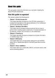
...on the motherboard. • Chapter 3: Powering up This chapter describes the power up sequence and gives information on the BIOS beep codes. • Chapter 4: BIOS setup This chapter tells how to install LAN, USB 2.0, and audio drivers under various operating systems. viii It includes ...it supports. • Chapter 2: Hardware information This chapter lists the hardware setup procedures that you need when installing the ASUS PP-DLW motherboard. About this guide is organized This manual contains the following parts: • Chapter 1: Product introduction This chapter describes the features...
...on the motherboard. • Chapter 3: Powering up This chapter describes the power up sequence and gives information on the BIOS beep codes. • Chapter 4: BIOS setup This chapter tells how to install LAN, USB 2.0, and audio drivers under various operating systems. viii It includes ...it supports. • Chapter 2: Hardware information This chapter lists the hardware setup procedures that you need when installing the ASUS PP-DLW motherboard. About this guide is organized This manual contains the following parts: • Chapter 1: Product introduction This chapter describes the features...
PP-DLW User Manual
Page 11
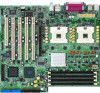
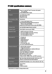
PP-DLW specifications summary CPU Chipsets Front Side Bus (FSB) Memory Onboard LAN Onboard audio Expansion slots Rear panel I/O Internal connectors BIOS features Form Factor Support CD contents Support for dual Intel® Xeon™ processor with speeds up to 3.06 GHz On-die 256KB... IDE LED/Power LED connectors 20-pin Front panel connector Chassis intrusion, SMBus, WOL, and WOR connectors 4Mb Flash ROM, AMI BIOS with ACPI, DMI, Green, PnP features, and Enhanced Server BIOS features Extended ATX form factor: 12 in x 10.5 in (30.5 cm x 26.7 cm) Device drivers Utilities Contact information...
PP-DLW specifications summary CPU Chipsets Front Side Bus (FSB) Memory Onboard LAN Onboard audio Expansion slots Rear panel I/O Internal connectors BIOS features Form Factor Support CD contents Support for dual Intel® Xeon™ processor with speeds up to 3.06 GHz On-die 256KB... IDE LED/Power LED connectors 20-pin Front panel connector Chassis intrusion, SMBus, WOL, and WOR connectors 4Mb Flash ROM, AMI BIOS with ACPI, DMI, Green, PnP features, and Enhanced Server BIOS features Extended ATX form factor: 12 in x 10.5 in (30.5 cm x 26.7 cm) Device drivers Utilities Contact information...
PP-DLW User Manual
Page 18
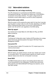
...power Interface (ACPI) provides more energy saving features for less than 4 seconds lets the system enter the soft-off mode, depending on the BIOS setting. Dual function power switch While the system is ON, pressing the power switch for operating systems that provides more than 4 seconds puts ... and HD/SCSI/MO/ZIP/CD/Floppy boot selection, and is removed. The system fan rotations per minute (RPM) is monitored by the ASUS ASIC to the memory and processor. Concurrent PCI This feature allows multiple PCI transfers from PCI master buses to prevent overheating and damage. 1.3.2...
...power Interface (ACPI) provides more energy saving features for less than 4 seconds lets the system enter the soft-off mode, depending on the BIOS setting. Dual function power switch While the system is ON, pressing the power switch for operating systems that provides more than 4 seconds puts ... and HD/SCSI/MO/ZIP/CD/Floppy boot selection, and is removed. The system fan rotations per minute (RPM) is monitored by the ASUS ASIC to the memory and processor. Concurrent PCI This feature allows multiple PCI transfers from PCI master buses to prevent overheating and damage. 1.3.2...

PP-DLW User Manual
Page 19
ASUS PP-DLW motherboard user guide 1-5 Color-coded connectors and descriptive icons make identification easy as required by the PC '99 specification. Compliance Both the BIOS and the hardware levels of the motherboard meet the stringent requirements for Windows NT/2000/XP. The new SDG 2.0 requirements for systems and components are based on the following high-level goals: support for Plug-and-Play compatibility and power management for configuring and managing all system components, 32-bit device drivers, and installation procedures for SDG 2.0 certification.
ASUS PP-DLW motherboard user guide 1-5 Color-coded connectors and descriptive icons make identification easy as required by the PC '99 specification. Compliance Both the BIOS and the hardware levels of the motherboard meet the stringent requirements for Windows NT/2000/XP. The new SDG 2.0 requirements for systems and components are based on the following high-level goals: support for Plug-and-Play compatibility and power management for configuring and managing all system components, 32-bit device drivers, and installation procedures for SDG 2.0 certification.
PP-DLW User Manual
Page 23
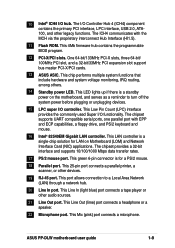
... This Line In (light blue) port connects a tape player or other devices. 19 RJ-45 port. This 4Mb firmware hub contains the programmable BIOS program. 12 PCI-X/PCI slots. This LED lights up if there is a standby power on Motherboard (LOM) and Network Interface Card (NIC) ...among others. 14 Standby power LED. The chipset provides a 32-bit interface and supports 10/100/1000 Mbps data transfer rates. 17 PS/2 mouse port. ASUS PP-DLW motherboard user guide 1-9 This Low Pin Count (LPC) interface provides the commonly used Super I /O hub. This Mic (pink) port connects a microphone. ...
... This Line In (light blue) port connects a tape player or other devices. 19 RJ-45 port. This 4Mb firmware hub contains the programmable BIOS program. 12 PCI-X/PCI slots. This LED lights up if there is a standby power on Motherboard (LOM) and Network Interface Card (NIC) ...among others. 14 Standby power LED. The chipset provides a 32-bit interface and supports 10/100/1000 Mbps data transfer rates. 17 PS/2 mouse port. ASUS PP-DLW motherboard user guide 1-9 This Low Pin Count (LPC) interface provides the commonly used Super I /O hub. This Mic (pink) port connects a microphone. ...

PP-DLW User Manual
Page 28
..., 100MHz 3V) Bridge Hub J16 AUDIO_COM1 J18 PCI-X3 (64-bit, 100MHz 3V) LED4 ASUS ASIC with Hardware Monitor PCI-X4 (64-bit, 133MHz 3V) 4Mbit Flash BIOS J20 PCI1 (32-bit, 33MHz 5V) FAN5 GAME1 J26 J33 PP-DLW J25 J31 BATTERY1 Intel I/O Controller Hub (ICH4) BUZZ1 J21 J22 J23 J24 FLOPPY Primary...
..., 100MHz 3V) Bridge Hub J16 AUDIO_COM1 J18 PCI-X3 (64-bit, 100MHz 3V) LED4 ASUS ASIC with Hardware Monitor PCI-X4 (64-bit, 133MHz 3V) 4Mbit Flash BIOS J20 PCI1 (32-bit, 33MHz 5V) FAN5 GAME1 J26 J33 PP-DLW J25 J31 BATTERY1 Intel I/O Controller Hub (ICH4) BUZZ1 J21 J22 J23 J24 FLOPPY Primary...
PP-DLW User Manual
Page 37
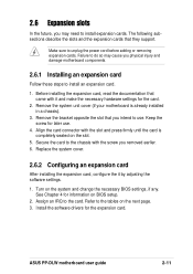
...cover. 2.6.2 Configuring an expansion card After installing the expansion card, configure the it and make the necessary hardware settings for later use . ASUS PP-DLW motherboard user guide 2-11 Before installing the expansion card, read the documentation that you intend to use . 4. Align the card connector with...installed in a chassis). 3. Remove the system unit cover (if your motherboard is completely seated on the system and change the necessary BIOS settings, if any. Make sure to the card. The following subsections describe the slots and the expansion cards that they support. ...
...cover. 2.6.2 Configuring an expansion card After installing the expansion card, configure the it and make the necessary hardware settings for later use . ASUS PP-DLW motherboard user guide 2-11 Before installing the expansion card, read the documentation that you intend to use . 4. Align the card connector with...installed in a chassis). 3. Remove the system unit cover (if your motherboard is completely seated on the system and change the necessary BIOS settings, if any. Make sure to the card. The following subsections describe the slots and the expansion cards that they support. ...
PP-DLW User Manual
Page 42
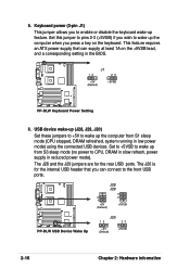
...the +5VSB lead, and a corresponding setting in the BIOS. Set to +5VSB to wake up the computer when you wish to wake up from S1 sleep mode (CPU stopped, DRAM refreshed, system running in reduced power mode). J28 J29 2 1 +5V (Default) 3 2 +5VSB PP-DLW PP-DLW USB Device Wake Up J20 12 23 +5V (... allows you can supply at least 1A on the keyboard. The J20 is for the rear USB ports. J1 12 23 +5V (Default) +5VSB PP-DLW PP-DLW Keyboard Power Setting 6. 5. The J28 and the J29 jumpers are for the internal USB header that can connect to CPU, DRAM in slow refresh, ...
...the +5VSB lead, and a corresponding setting in the BIOS. Set to +5VSB to wake up the computer when you wish to wake up from S1 sleep mode (CPU stopped, DRAM refreshed, system running in reduced power mode). J28 J29 2 1 +5V (Default) 3 2 +5VSB PP-DLW PP-DLW USB Device Wake Up J20 12 23 +5V (... allows you can supply at least 1A on the keyboard. The J20 is for the rear USB ports. J1 12 23 +5V (Default) +5VSB PP-DLW PP-DLW Keyboard Power Setting 6. 5. The J28 and the J29 jumpers are for the internal USB header that can connect to CPU, DRAM in slow refresh, ...
PP-DLW User Manual
Page 43
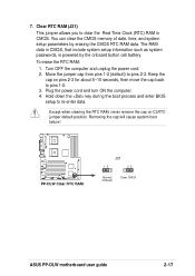
...pins 1-2 (default) to pins 1-2. 3. Keep the cap on CLRTC jumper default position. Hold down the key during the boot process and enter BIOS setup to clear the Real Time Clock (RTC) RAM in CMOS, that include system setup information such as system passwords, is powered by erasing...You can clear the CMOS memory of date, time, and system setup parameters by the onboard button cell battery. PP-DLW PP-DLW Clear RTC RAM J21 12 23 Normal (Default) Clear CMOS ASUS PP-DLW motherboard user guide 2-17 Plug the power cord and turn ON the computer. 4. Turn OFF the computer and ...
...pins 1-2 (default) to pins 1-2. 3. Keep the cap on CLRTC jumper default position. Hold down the key during the boot process and enter BIOS setup to clear the Real Time Clock (RTC) RAM in CMOS, that include system setup information such as system passwords, is powered by erasing...You can clear the CMOS memory of date, time, and system setup parameters by the onboard button cell battery. PP-DLW PP-DLW Clear RTC RAM J21 12 23 Normal (Default) Clear CMOS ASUS PP-DLW motherboard user guide 2-17 Plug the power cord and turn ON the computer. 4. Turn OFF the computer and ...
PP-DLW User Manual
Page 45
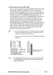
... for the jumper settings. PIN 1 PIN 1 Secondary IDE Connector Primary IDE Connector PP-DLW PP-DLW IDE Connectors NOTE: Orient the red markings (usually zigzag) on the UltraDMA/100/66 cable is intentional. ASUS PP-DLW motherboard user guide 2-19 You may configure two hard disks to the hard disk ...connect the gray connector to the UltraDMA/100/66 slave device (hard disk drive) and the black connector to the secondary IDE connector. BIOS supports specific device bootup. Pin 20 on each IDE connector is recommended that you connect the cables. 2. 3. one for the primary...
... for the jumper settings. PIN 1 PIN 1 Secondary IDE Connector Primary IDE Connector PP-DLW PP-DLW IDE Connectors NOTE: Orient the red markings (usually zigzag) on the UltraDMA/100/66 cable is intentional. ASUS PP-DLW motherboard user guide 2-19 You may configure two hard disks to the hard disk ...connect the gray connector to the UltraDMA/100/66 slave device (hard disk drive) and the black connector to the secondary IDE connector. BIOS supports specific device bootup. Pin 20 on each IDE connector is recommended that you connect the cables. 2. 3. one for the primary...
PP-DLW User Manual
Page 49
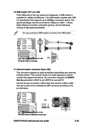
... connection speed. J26 Front View Back View IRTX GND IRRX +5V 1 PP-DLW PP-DLW Infrared Module Connector ASUS PP-DLW motherboard user guide IRTX GND IRRX +5V (NC) 2-23 Use the five pins as shown in BIOS to the USB header. USB+5V LDM1 LDP1 GND NC PP-DLW PP-DLW USB 2.0 Header 1 5 J25 6 10 USB+5V LDM2 LDP2 GND 11...
... connection speed. J26 Front View Back View IRTX GND IRRX +5V 1 PP-DLW PP-DLW Infrared Module Connector ASUS PP-DLW motherboard user guide IRTX GND IRRX +5V (NC) 2-23 Use the five pins as shown in BIOS to the USB header. USB+5V LDM1 LDP1 GND NC PP-DLW PP-DLW USB 2.0 Header 1 5 J25 6 10 USB+5V LDM2 LDP2 GND 11...
PP-DLW User Manual
Page 52
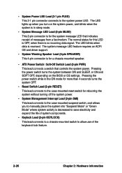
... power LED. • System Power LED Lead (3-1 pin PLED) This 3-1 pin connector connects to the case-mounted suspend switch, and allows you turn on the BIOS or OS settings. Pressing the power switch while in the ON mode for more than 4 seconds turns the system OFF. • Reset Switch Lead (2-pin...
... power LED. • System Power LED Lead (3-1 pin PLED) This 3-1 pin connector connects to the case-mounted suspend switch, and allows you turn on the BIOS or OS settings. Pressing the power switch while in the ON mode for more than 4 seconds turns the system OFF. • Reset Switch Lead (2-pin...

PP-DLW User Manual
Page 53
Powering up sequence and gives information on the BIOS beep codes. Chapter 3 This chapter describes the power up
Powering up sequence and gives information on the BIOS beep codes. Chapter 3 This chapter describes the power up

PP-DLW User Manual
Page 55
...BIOS Setup. While the tests are off after Windows shuts down to a power outlet that all the connections, replace the system case cover. 2. If you use Windows 2000/XP, click the Start button, click Shut Down, then click the OK button to the power connector at the back of the chassis). 6. ASUS PP-DLW... on . 3.1 Starting up for assistance. 7. The system then runs the power-on the screen. After making all switches are running, the BIOS beeps or additional messages appear on tests. If you do not see anything within 30 seconds from the time you can now safely turn off ...
...BIOS Setup. While the tests are off after Windows shuts down to a power outlet that all the connections, replace the system case cover. 2. If you use Windows 2000/XP, click the Start button, click Shut Down, then click the OK button to the power connector at the back of the chassis). 6. ASUS PP-DLW... on . 3.1 Starting up for assistance. 7. The system then runs the power-on the screen. After making all switches are running, the BIOS beeps or additional messages appear on tests. If you do not see anything within 30 seconds from the time you can now safely turn off ...

PP-DLW User Manual
Page 57
BIOS setup Chapter 4 This chapter tells how to change system settings through the BIOS Setup menus. Detailed descriptions of the BIOS parameters are also provided.
BIOS setup Chapter 4 This chapter tells how to change system settings through the BIOS Setup menus. Detailed descriptions of the BIOS parameters are also provided.

PP-DLW User Manual
Page 58
Chapter summary 4.1 Managing and updating your BIOS 4-1 4.2 BIOS Setup program 4-5 4.3 Main menu 4-8 4.4 Advanced menu 4-9 4.5 PCI PnP menu 4-19 4.6 Boot menu 4-22 4.7 Security menu 4-27 4.8 Chipset menu 4-28 4.9 Power menu 4-33 4.10 Exit menu 4-34 ASUS PP-DLW motherboard
Chapter summary 4.1 Managing and updating your BIOS 4-1 4.2 BIOS Setup program 4-5 4.3 Main menu 4-8 4.4 Advanced menu 4-9 4.5 PCI PnP menu 4-19 4.6 Boot menu 4-22 4.7 Security menu 4-27 4.8 Chipset menu 4-28 4.9 Power menu 4-33 4.10 Exit menu 4-34 ASUS PP-DLW motherboard

PP-DLW User Manual
Page 59
... you wish to obtain BIOS updates for this motherboard. 4. ASUS PP-DLW motherboard user guide 4-1 Visit the ASUS website (www.asus.com) to update current BIOS on the motherboard. Type the command line afudos /filename.rom, where "filename.rom" means the original or latest BIOS file with the new BIOS. The screen displays the...5. The screen displays the status of the utility. 3. Press Enter. Insert the floppy disk into a floppy disk. 2. 4.1 Managing and updating your BIOS To update the BIOS, use the AFUDOS.EXE utility in DOS mode. 1. Copy the AFUDOS.EXE utility and the latest...
... you wish to obtain BIOS updates for this motherboard. 4. ASUS PP-DLW motherboard user guide 4-1 Visit the ASUS website (www.asus.com) to update current BIOS on the motherboard. Type the command line afudos /filename.rom, where "filename.rom" means the original or latest BIOS file with the new BIOS. The screen displays the...5. The screen displays the status of the utility. 3. Press Enter. Insert the floppy disk into a floppy disk. 2. 4.1 Managing and updating your BIOS To update the BIOS, use the AFUDOS.EXE utility in DOS mode. 1. Copy the AFUDOS.EXE utility and the latest...

PP-DLW User Manual
Page 60
... to configure your system using the provided utility described in section "4.1 Managing and updating your BIOS." It is designed to make your selections among the predetermined choices. Use the BIOS Setup program when you may not exactly match what you can update using this last option...This requires you can scroll through the various sub-menus and make it as easy to "Run Setup". Because the BIOS software is constantly being updated, the following BIOS setup screens and descriptions are installing a motherboard, reconfiguring your system, or prompted to use the Setup program, you...
... to configure your system using the provided utility described in section "4.1 Managing and updating your BIOS." It is designed to make your selections among the predetermined choices. Use the BIOS Setup program when you may not exactly match what you can update using this last option...This requires you can scroll through the various sub-menus and make it as easy to "Run Setup". Because the BIOS software is constantly being updated, the following BIOS setup screens and descriptions are installing a motherboard, reconfiguring your system, or prompted to use the Setup program, you...

PP-DLW User Manual
Page 61
ASUS PP-DLW motherboard user guide 4-3 4.2.1 BIOS menu screen Menu bar General help Menu items Field setting Navigation keys 4.2.2 Menu bar The menu bar on top of the screen has the following ...
ASUS PP-DLW motherboard user guide 4-3 4.2.1 BIOS menu screen Menu bar General help Menu items Field setting Navigation keys 4.2.2 Menu bar The menu bar on top of the screen has the following ...


