
PP-DLW User Manual
Page 3
... viii ASUS contact information x PP-DLW specifications summary xi Chapter 1: Product introduction 1.1 Welcome 1-1 1.2 Package contents 1-1 1.3 Special features 1-2 1.3.1 Product highlights 1-2 1.3.2 Value-added solutions 1-4 Chapter 2: Hardware information 2.1 Motherboard installation 2-1 2.1.1 Placement direction 2-1 2.1.2 Screw holes 2-1 2.2 Motherboard layout 2-2 2.3 Before you proceed 2-3 2.4 Central Processing Unit (CPU 2-4 2.4.1 Overview 2-4 2.4.2 Installing the CPU 2-5 2.4.3 Installing the CPU heatsink and fan 2-6 2.5 System memory 2-8 2.5.1 Overview 2-8 2.5.2 Memory...
... viii ASUS contact information x PP-DLW specifications summary xi Chapter 1: Product introduction 1.1 Welcome 1-1 1.2 Package contents 1-1 1.3 Special features 1-2 1.3.1 Product highlights 1-2 1.3.2 Value-added solutions 1-4 Chapter 2: Hardware information 2.1 Motherboard installation 2-1 2.1.1 Placement direction 2-1 2.1.2 Screw holes 2-1 2.2 Motherboard layout 2-2 2.3 Before you proceed 2-3 2.4 Central Processing Unit (CPU 2-4 2.4.1 Overview 2-4 2.4.2 Installing the CPU 2-5 2.4.3 Installing the CPU heatsink and fan 2-6 2.5 System memory 2-8 2.5.1 Overview 2-8 2.5.2 Memory...

PP-DLW User Manual
Page 4
... 4-1 4.2 BIOS Setup program 4-2 4.2.1 BIOS menu screen 4-3 4.2.2 Menu bar 4-3 4.2.3 Navigation keys 4-4 4.2.4 General help 4-4 4.2.5 Sub-menu 4-4 4.2.6 Scroll bar 4-4 4.2.7 Pop-up window 4-4 4.3 Main menu 4-5 4.3.1 AMI BIOS 4-5 4.3.2 Processor 4-5 4.3.3 System Memory 4-5 4.3.4 System Time [xx:xx:xxxx 4-5 4.3.5 System Date [Day xx/xx/xxxx 4-5 4.4 Advanced menu 4-6 4.4.1 CPU Configuration 4-6 4.4.2 IDE Configuration 4-7 4.4.3 Floppy Configuration 4-10 4.4.4 Super IO Configuration 4-10 4.4.5 ACPI...
... 4-1 4.2 BIOS Setup program 4-2 4.2.1 BIOS menu screen 4-3 4.2.2 Menu bar 4-3 4.2.3 Navigation keys 4-4 4.2.4 General help 4-4 4.2.5 Sub-menu 4-4 4.2.6 Scroll bar 4-4 4.2.7 Pop-up window 4-4 4.3 Main menu 4-5 4.3.1 AMI BIOS 4-5 4.3.2 Processor 4-5 4.3.3 System Memory 4-5 4.3.4 System Time [xx:xx:xxxx 4-5 4.3.5 System Date [Day xx/xx/xxxx 4-5 4.4 Advanced menu 4-6 4.4.1 CPU Configuration 4-6 4.4.2 IDE Configuration 4-7 4.4.3 Floppy Configuration 4-10 4.4.4 Super IO Configuration 4-10 4.4.5 ACPI...
PP-DLW User Manual
Page 11
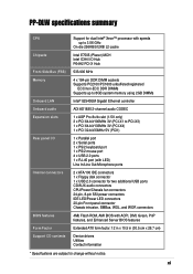
xi PP-DLW specifications summary CPU Chipsets Front Side Bus (FSB) Memory Onboard LAN Onboard audio Expansion slots Rear panel I/O Internal connectors BIOS features Form Factor Support CD contents Support for dual Intel® Xeon™ processor ... PCI-X Hub 533/400 MHz 4 x 184-pin DDR DIMM sockets Supports PC2100/PC1600 unbuffered/registered ECC/non-ECC DDR DIMMs Supports up to 8GB system memory using 2GB DIMMs Intel® 82540EM Gigabit Ethernet controller ADI AD1885 2-channel audio CODEC 1 x AGP Pro 8x/4x slot (1.5V only) 3 x PCI 64-bit/100MHz...
xi PP-DLW specifications summary CPU Chipsets Front Side Bus (FSB) Memory Onboard LAN Onboard audio Expansion slots Rear panel I/O Internal connectors BIOS features Form Factor Support CD contents Support for dual Intel® Xeon™ processor ... PCI-X Hub 533/400 MHz 4 x 184-pin DDR DIMM sockets Supports PC2100/PC1600 unbuffered/registered ECC/non-ECC DDR DIMMs Supports up to 8GB system memory using 2GB DIMMs Intel® 82540EM Gigabit Ethernet controller ADI AD1885 2-channel audio CODEC 1 x AGP Pro 8x/4x slot (1.5V only) 3 x PCI 64-bit/100MHz...

PP-DLW User Manual
Page 16
...Intel® 82540EM Gigabit LAN controller to deliver the required bandwidth for more information. DDR memory support Employing the Double Data Rate (DDR) memory technology, the PP-DLW motherboard supports up to 8GB of system memory using PC2100/1600 unbuffered/registered ECC/non-ECC DDR DIMMs. The ultra-fast 266MHz... memory bus doubles the speed of its predecessor AGP 4X. AGP Pro 8x/4X slot The ...
...Intel® 82540EM Gigabit LAN controller to deliver the required bandwidth for more information. DDR memory support Employing the Double Data Rate (DDR) memory technology, the PP-DLW motherboard supports up to 8GB of system memory using PC2100/1600 unbuffered/registered ECC/non-ECC DDR DIMMs. The ultra-fast 266MHz... memory bus doubles the speed of its predecessor AGP 4X. AGP Pro 8x/4X slot The ...
PP-DLW User Manual
Page 18
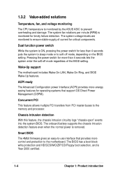
.../SCSI/MO/ZIP/CD/Floppy boot selection, and is removed. 1.3.2 Value-added solutions Temperature, fan, and voltage monitoring The CPU temperature is monitored by the ASUS ASIC to the memory and processor.
.../SCSI/MO/ZIP/CD/Floppy boot selection, and is removed. 1.3.2 Value-added solutions Temperature, fan, and voltage monitoring The CPU temperature is monitored by the ASUS ASIC to the memory and processor.
PP-DLW User Manual
Page 22
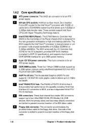
...to deliver up to 4.2GBps or 3.2GBps data transfer rates. The P64H2 is PCI/PCI-X 64-bit Hub 2 that allows up to 8GB system memory. 4 8-pin 12V SSI power connector. One side of the connector is designed for the floppy disk drive. These dual-channel bus master IDE ...incorrect insertion of the floppy disk cable. 1-8 Chapter 1: Product introduction Both the primary (blue) and secondary (black) connectors are slotted to 8GB system memory using unbuffered/registered ECC/non-ECC PC2100/1600 DDR DIMMs. 6 AGP Pro 8X slot. These four 184-pin DIMM sockets support up to prevent incorrect...
...to deliver up to 4.2GBps or 3.2GBps data transfer rates. The P64H2 is PCI/PCI-X 64-bit Hub 2 that allows up to 8GB system memory. 4 8-pin 12V SSI power connector. One side of the connector is designed for the floppy disk drive. These dual-channel bus master IDE ...incorrect insertion of the floppy disk cable. 1-8 Chapter 1: Product introduction Both the primary (blue) and secondary (black) connectors are slotted to 8GB system memory using unbuffered/registered ECC/non-ECC PC2100/1600 DDR DIMMs. 6 AGP Pro 8X slot. These four 184-pin DIMM sockets support up to prevent incorrect...
PP-DLW User Manual
Page 26
Chapter summary 2.1 Motherboard installation 2-1 2.2 Motherboard layout 2-2 2.3 Before you proceed 2-3 2.4 Central Processing Unit (CPU 2-4 2.5 System memory 2-8 2.6 Expansion slots 2-11 2.7 Jumpers 2-14 2.8 Connectors 2-18 ASUS PP-DLW motherboard
Chapter summary 2.1 Motherboard installation 2-1 2.2 Motherboard layout 2-2 2.3 Before you proceed 2-3 2.4 Central Processing Unit (CPU 2-4 2.5 System memory 2-8 2.6 Expansion slots 2-11 2.7 Jumpers 2-14 2.8 Connectors 2-18 ASUS PP-DLW motherboard
PP-DLW User Manual
Page 34
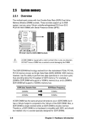
... 184-pin footprint compared to the 168-pin of SDR memory. DO NOT force a DIMM into a socket to 8GB system memory using 184-pin unbuffered/registered ECC/non-ECC PC2100/1600 DIMMs with Serial Presence Detect (SPD). 80 Pins 104 Pins PP-DLW PP-DLW 184-Pin DDR DIMM Sockets A DDR DIMM is double ...notched. The DDR SDRAM technology evolved from the mainstream PC66, PC100, PC133 memory known as an SDR DIMM, but it fits in only one clock cycle, ...
... 184-pin footprint compared to the 168-pin of SDR memory. DO NOT force a DIMM into a socket to 8GB system memory using 184-pin unbuffered/registered ECC/non-ECC PC2100/1600 DIMMs with Serial Presence Detect (SPD). 80 Pins 104 Pins PP-DLW PP-DLW 184-Pin DDR DIMM Sockets A DDR DIMM is double ...notched. The DDR SDRAM technology evolved from the mainstream PC66, PC100, PC133 memory known as an SDR DIMM, but it fits in only one clock cycle, ...

PP-DLW User Manual
Page 35
.../CPU FSB synchronization CPU FSB 533 MHz 400 MHz DDR DIMM Type PC2100 PC1600 Memory Frequency 266 MHz 200 MHz ASUS PP-DLW motherboard user guide 2-9 2.5.2 Memory Configurations You may cause memory sizing error or system boot failure. Make sure that the memory frequency matches the CPU FSB (Front Side Bus). Refer to Table 2 below. 4. Installing DDR...
.../CPU FSB synchronization CPU FSB 533 MHz 400 MHz DDR DIMM Type PC2100 PC1600 Memory Frequency 266 MHz 200 MHz ASUS PP-DLW motherboard user guide 2-9 2.5.2 Memory Configurations You may cause memory sizing error or system boot failure. Make sure that the memory frequency matches the CPU FSB (Front Side Bus). Refer to Table 2 below. 4. Installing DDR...
PP-DLW User Manual
Page 43
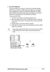
...) This jumper allows you to pins 1-2. 3. The RAM data in CMOS. Plug the power cord and turn ON the computer. 4. PP-DLW PP-DLW Clear RTC RAM J21 12 23 Normal (Default) Clear CMOS ASUS PP-DLW motherboard user guide 2-17 Hold down the key during the boot process and enter BIOS setup to pins 2-3. Move the... in CMOS, that include system setup information such as system passwords, is powered by erasing the CMOS RTC RAM data. You can clear the CMOS memory of date, time, and system setup parameters by the onboard button cell battery.
...) This jumper allows you to pins 1-2. 3. The RAM data in CMOS. Plug the power cord and turn ON the computer. 4. PP-DLW PP-DLW Clear RTC RAM J21 12 23 Normal (Default) Clear CMOS ASUS PP-DLW motherboard user guide 2-17 Hold down the key during the boot process and enter BIOS setup to pins 2-3. Move the... in CMOS, that include system setup information such as system passwords, is powered by erasing the CMOS RTC RAM data. You can clear the CMOS memory of date, time, and system setup parameters by the onboard button cell battery.

PP-DLW User Manual
Page 63
ASUS PP-DLW motherboard user guide 4-5 Refer to section "4.2.1 BIOS menu screen" for information on the menu screen items and how to navigate through them. 4.3.1 AMI BIOS This item displays the auto-detected BIOS information. 4.3.2 Processor This item displays the auto-detected CPU specification. 4.3.3 System Memory This item displays the auto-detected system memory installed. 4.3.4 System...
ASUS PP-DLW motherboard user guide 4-5 Refer to section "4.2.1 BIOS menu screen" for information on the menu screen items and how to navigate through them. 4.3.1 AMI BIOS This item displays the auto-detected BIOS information. 4.3.2 Processor This item displays the auto-detected CPU specification. 4.3.3 System Memory This item displays the auto-detected system memory installed. 4.3.4 System...

PP-DLW User Manual
Page 74
... required for the PCI device latency timer register. configuration options: [Disabled] [Enabled] 4-16 Chapter 4: BIOS Setup When set to change the advanced settings for shadow memory. Configuration options: [32] [64] [96] [128] [160] [192] [224] [248] 4.5.3 Pallete Snooping [Enabled] When set to [Disabled] deactivates this feature. The menu includes setting IRQ...
... required for the PCI device latency timer register. configuration options: [Disabled] [Enabled] 4-16 Chapter 4: BIOS Setup When set to change the advanced settings for shadow memory. Configuration options: [32] [64] [96] [128] [160] [192] [224] [248] 4.5.3 Pallete Snooping [Enabled] When set to [Disabled] deactivates this feature. The menu includes setting IRQ...

PP-DLW User Manual
Page 75
Configuration options: [Disabled] [Enabled] ASUS PP-DLW motherboard user guide 4-17 Configuration options: [Disabled] [Enabled] 4.5.5 Onboard LAN Option ROM Keep [Enabled] This item allows you to enable or disable copying the PCI device option ROM to shadow memory. 4.5.4 Slot 1, Slot 2, Slot 3, Slot 4, Slot 5 Option ROM Keep [Enabled] These items allow you to enable or disable copying the onboard LAN option ROM to shadow memory.
Configuration options: [Disabled] [Enabled] ASUS PP-DLW motherboard user guide 4-17 Configuration options: [Disabled] [Enabled] 4.5.5 Onboard LAN Option ROM Keep [Enabled] This item allows you to enable or disable copying the PCI device option ROM to shadow memory. 4.5.4 Slot 1, Slot 2, Slot 3, Slot 4, Slot 5 Option ROM Keep [Enabled] These items allow you to enable or disable copying the onboard LAN option ROM to shadow memory.


