

User Guide
Page 6
... Extreme Memory Profile (XMP) * Hyper DIMM support is damaged or missing, contact your retailer. Supports DVI-D with max. PIO-B85M specifications summary CPU Chipset Memory Graphics Expansion slots Storage LAN LGA1150 socket for the 4th Generation Intel® CoreTM i7/ CoreTM ... Controller (continued on the CPU types. ** Refer to www.asus.com for the latest Memory QVL (Qualified Vendors List). Package contents Check your motherboard package for the following items. Motherboard Cables Accessories Application DVD Documentation ASUS PIO-B85M motherboard 1 x Serial ATA 6.0 Gb/s cable 1 x ...
... Extreme Memory Profile (XMP) * Hyper DIMM support is damaged or missing, contact your retailer. Supports DVI-D with max. PIO-B85M specifications summary CPU Chipset Memory Graphics Expansion slots Storage LAN LGA1150 socket for the 4th Generation Intel® CoreTM i7/ CoreTM ... Controller (continued on the CPU types. ** Refer to www.asus.com for the latest Memory QVL (Qualified Vendors List). Package contents Check your motherboard package for the following items. Motherboard Cables Accessories Application DVD Documentation ASUS PIO-B85M motherboard 1 x Serial ATA 6.0 Gb/s cable 1 x ...
User Guide
Page 9
ASUS PIO-B85M 1-1 Failure to do so may cause severe damage to avoid touching the ICs on a grounded antistatic pad or in the bag that came with the ...
ASUS PIO-B85M 1-1 Failure to do so may cause severe damage to avoid touching the ICs on a grounded antistatic pad or in the bag that came with the ...

User Guide
Page 11
...12. USB 3.0 connector (20-1 pin USB3_12) Page 1-15 1-4 1-17 1-7 1-17 1-18 1-21 1-16 1-12 1-20 1-20 1-16 1-19 1-18 ASUS PIO-B85M 1-3 System panel connector (10-1 pin F_PANEL) 8. Speaker connector (4-pin SPEAKER) 9. Clear RTC RAM (2-pin CLRTC) 10. USB 2.0 connector (10-1 pin USB1314) 14... Serial ATA 3.0Gb/s connectors (7-pin SATA3G_1~2) 6. 1.2.3 Motherboard layout 1 21.1cm(8.3n) PCIEX16_1 2 34 CPU_FAN KBMS DIGI +VRM ATX12V PIO-B85M EATXPWR DDR3 DIMM_B1 (64bit, 240-pin module) DDR3 DIMM_A1 (64bit, 240-pin module) DVI VGA BATTERY USB1314 USB3_12 14 USB910 13 USB3_56 ...
...12. USB 3.0 connector (20-1 pin USB3_12) Page 1-15 1-4 1-17 1-7 1-17 1-18 1-21 1-16 1-12 1-20 1-20 1-16 1-19 1-18 ASUS PIO-B85M 1-3 System panel connector (10-1 pin F_PANEL) 8. Speaker connector (4-pin SPEAKER) 9. Clear RTC RAM (2-pin CLRTC) 10. USB 2.0 connector (10-1 pin USB1314) 14... Serial ATA 3.0Gb/s connectors (7-pin SATA3G_1~2) 6. 1.2.3 Motherboard layout 1 21.1cm(8.3n) PCIEX16_1 2 34 CPU_FAN KBMS DIGI +VRM ATX12V PIO-B85M EATXPWR DDR3 DIMM_B1 (64bit, 240-pin module) DDR3 DIMM_A1 (64bit, 240-pin module) DVI VGA BATTERY USB1314 USB3_12 14 USB910 13 USB3_56 ...

User Guide
Page 15
...) Dual Inline Memory Module (DIMM) sockets. The figure illustrates the location of the DDR3 DIMM sockets: DIMM_A1 DIMM_B1 Channel Sockets Channel A DIMM_A1 PIO-B85M Channel B DIMM_B1 PIO-B85M 240-pin DDR3 DIMM sockets ASUS PIO-B85M 1-7 To uninstall the CPU heatsink and fan assembly 1 2 A B B A 1.4 System memory 1.4.1 Overview This motherboard comes with less power consumption. A DDR3 module has...
...) Dual Inline Memory Module (DIMM) sockets. The figure illustrates the location of the DDR3 DIMM sockets: DIMM_A1 DIMM_B1 Channel Sockets Channel A DIMM_A1 PIO-B85M Channel B DIMM_B1 PIO-B85M 240-pin DDR3 DIMM sockets ASUS PIO-B85M 1-7 To uninstall the CPU heatsink and fan assembly 1 2 A B B A 1.4 System memory 1.4.1 Overview This motherboard comes with less power consumption. A DDR3 module has...

User Guide
Page 17
1.4.3 1 Installing a DIMM 2 3 To remove a DIMM B A ASUS PIO-B85M 1-9
1.4.3 1 Installing a DIMM 2 3 To remove a DIMM B A ASUS PIO-B85M 1-9

User Guide
Page 19
shared - - - - - - - - shared - - - - shared - - - - IRQ assignments for this motherboard IGD Audio controller EHCI controller 1 EHCI controller 2 XHCI controller SATA controller PCIE X16_1 RTL8111GR A B C D E F G H shared - - - - - - - - - - - - - shared - - - - - shared - - - - - - ASUS PIO-B85M 1-11 shared - - - - - - - - shared - - - - - - - -
shared - - - - - - - - shared - - - - shared - - - - IRQ assignments for this motherboard IGD Audio controller EHCI controller 1 EHCI controller 2 XHCI controller SATA controller PCIE X16_1 RTL8111GR A B C D E F G H shared - - - - - - - - - - - - - shared - - - - - shared - - - - - - ASUS PIO-B85M 1-11 shared - - - - - - - - shared - - - - - - - -

User Guide
Page 21
... link Orange Linked Orange Data activity (Blinking) Orange Ready to a Local Area Network (LAN) through a network hub. Line In port (light blue). Microphone port (pink). ASUS PIO-B85M 1-13 PS/2 Mouse port (green). This port is for a VGA monitor or other audio sources. 5. This port allows Gigabit connection to (Blinking then wake up...
... link Orange Linked Orange Data activity (Blinking) Orange Ready to a Local Area Network (LAN) through a network hub. Line In port (light blue). Microphone port (pink). ASUS PIO-B85M 1-13 PS/2 Mouse port (green). This port is for a VGA monitor or other audio sources. 5. This port allows Gigabit connection to (Blinking then wake up...

User Guide
Page 23
...system will not boot up if the power is inadequate. • If you intend to the Recommended Power Supply Wattage Calculator at http://support.asus. ASUS PIO-B85M 1-15 The system may become unstable or may not boot up . • We recommend that you use a PSU with higher power output...for ATX power supply plugs. ATX12V EATXPWR +12V DC +12V DC +3 Volts +12 Volts +12 Volts PIO-B85M +5V Standby Power OK GND PIN 1 +5 Volts GND GND GND +5 Volts GND +3 Volts +3 Volts PIN 1 PIO-B85M ATX power connectors GND +5 Volts +5 Volts +5 Volts -5 Volts GND GND GND PSON# GND -12 ...
...system will not boot up if the power is inadequate. • If you intend to the Recommended Power Supply Wattage Calculator at http://support.asus. ASUS PIO-B85M 1-15 The system may become unstable or may not boot up . • We recommend that you use a PSU with higher power output...for ATX power supply plugs. ATX12V EATXPWR +12V DC +12V DC +3 Volts +12 Volts +12 Volts PIO-B85M +5V Standby Power OK GND PIN 1 +5 Volts GND GND GND +5 Volts GND +3 Volts +3 Volts PIN 1 PIO-B85M ATX power connectors GND +5 Volts +5 Volts +5 Volts -5 Volts GND GND GND PSON# GND -12 ...

User Guide
Page 25
Only 4-pin CPU fans and chassis fans support the ASUS FAN Xpert feature. 5. PIO-B85M SATA3G_2 GND RSATA_TXP2 RSATA_TXN2 GND RSATA_RXN2 RSATA_RXP2 GND SATA3G_1 GND RSATA_TXP1 RSATA_TXN1 GND RSATA_RXN1 RSATA_RXP1 GND PIO-B85M SATA 3.0Gb/s connectors When using hot-plug and NCQ, set the ...fan power. The CPU_FAN connector supports a CPU fan of the connector. See section 2.6.3 SATA Configuration for details. These are not jumpers! ASUS PIO-B85M 1-17 Intel® B85 Serial ATA 3.0Gb/s connectors (7-pin SATA3G_1~2 [dark brown]) These connectors connect to [AHCI]. CPU and ...
Only 4-pin CPU fans and chassis fans support the ASUS FAN Xpert feature. 5. PIO-B85M SATA3G_2 GND RSATA_TXP2 RSATA_TXN2 GND RSATA_RXN2 RSATA_RXP2 GND SATA3G_1 GND RSATA_TXP1 RSATA_TXN1 GND RSATA_RXN1 RSATA_RXP1 GND PIO-B85M SATA 3.0Gb/s connectors When using hot-plug and NCQ, set the ...fan power. The CPU_FAN connector supports a CPU fan of the connector. See section 2.6.3 SATA Configuration for details. These are not jumpers! ASUS PIO-B85M 1-17 Intel® B85 Serial ATA 3.0Gb/s connectors (7-pin SATA3G_1~2 [dark brown]) These connectors connect to [AHCI]. CPU and ...

User Guide
Page 27
USB 2.0 connector (10-1 pin USB1314) This connector is purchased separately. PIO-B85M USB1314 NC GND USB_P13+ USB_P13USB+5V GND USB_P14+ USB_P14USB+5V PIN 1 PIO-B85M USB2.0 connector Never connect a 1394 cable to 480Mbps connection speed. Doing so will damage the motherboard! ASUS PIO-B85M 1-19 This USB connector complies with USB 2.0 specifications and supports up to the USB connectors. The USB 2.0 module is for USB 2.0 ports. Connect the USB module cable to this connector, then install the module to a slot opening at the back of the system chassis. 8.
USB 2.0 connector (10-1 pin USB1314) This connector is purchased separately. PIO-B85M USB1314 NC GND USB_P13+ USB_P13USB+5V GND USB_P14+ USB_P14USB+5V PIN 1 PIO-B85M USB2.0 connector Never connect a 1394 cable to 480Mbps connection speed. Doing so will damage the motherboard! ASUS PIO-B85M 1-19 This USB connector complies with USB 2.0 specifications and supports up to the USB connectors. The USB 2.0 module is for USB 2.0 ports. Connect the USB module cable to this connector, then install the module to a slot opening at the back of the system chassis. 8.

User Guide
Page 29
PWR_BTN PWR_LED+ PWR_LEDPWR GND PIO-B85M PIN 1 HDD_LED+ HDD_LED- ASUS PIO-B85M 1-21 Ground HWRST# (NC) +HDD_LED- Connect the HDD Activity LED cable to this connector. The system power LED lights up or flashes when data is ... mode. • Hard disk drive activity LED (2-pin +HDD_LED-) This 2-pin connector is for the chassis-mounted reset button for the system power LED. RESET PIO-B85M System panel connector • System power LED (2-pin +PWR_LED-) This 2-pin connector is for system reboot without turning off button (2-pin PWR_BTN) This connector is...
PWR_BTN PWR_LED+ PWR_LEDPWR GND PIO-B85M PIN 1 HDD_LED+ HDD_LED- ASUS PIO-B85M 1-21 Ground HWRST# (NC) +HDD_LED- Connect the HDD Activity LED cable to this connector. The system power LED lights up or flashes when data is ... mode. • Hard disk drive activity LED (2-pin +HDD_LED-) This 2-pin connector is for the chassis-mounted reset button for the system power LED. RESET PIO-B85M System panel connector • System power LED (2-pin +PWR_LED-) This 2-pin connector is for system reboot without turning off button (2-pin PWR_BTN) This connector is...

User Guide
Page 31
...flash disk in case you can also manually update the saved BIOS and select a boot logo when the system goes into POST. ASUS PIO-B85M 2-1 BIOS information 2.1 Managing and updating your motherboard's softwares, drivers and the BIOS version easily. Copy the original motherboard BIOS using the... ASUS Update utility. 2.1.1 EZ Update EZ Update is a utility that allows you to update the BIOS EZ Update requires an Internet connection ...
...flash disk in case you can also manually update the saved BIOS and select a boot logo when the system goes into POST. ASUS PIO-B85M 2-1 BIOS information 2.1 Managing and updating your motherboard's softwares, drivers and the BIOS version easily. Copy the original motherboard BIOS using the... ASUS Update utility. 2.1.1 EZ Update EZ Update is a utility that allows you to update the BIOS EZ Update requires an Internet connection ...
User Guide
Page 33
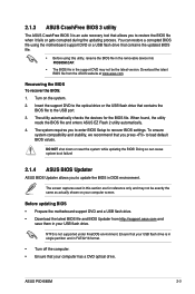
... the motherboard support DVD or a USB flash drive that contains the BIOS file to load default BIOS values. You can cause system boot failure! 2.1.4 ASUS BIOS Updater ASUS BIOS Updater allows you to update the BIOS in FAT32/16 format. • Turn off the computer. • Ensure that you press to the... drive. Before updating BIOS • Prepare the motherboard support DVD and a USB flash drive. • Download the latest BIOS file and BIOS Updater from the ASUS website at www.asus.com. ASUS PIO-B85M 2-3
... the motherboard support DVD or a USB flash drive that contains the BIOS file to load default BIOS values. You can cause system boot failure! 2.1.4 ASUS BIOS Updater ASUS BIOS Updater allows you to update the BIOS in FAT32/16 format. • Turn off the computer. • Ensure that you press to the... drive. Before updating BIOS • Prepare the motherboard support DVD and a USB flash drive. • Download the latest BIOS file and BIOS Updater from the ASUS website at www.asus.com. ASUS PIO-B85M 2-3
User Guide
Page 35
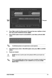
...The BIOS Backup feature is done, press to exit BIOS Updater. 6. When BIOS update is not supported due to ensure system compatibility and stability. ASUS PIO-B85M 2-5 Press to switch from Drives panel to Files panel then press keys to confirm the BIOS update. Are you sure you want to prevent ... the system while updating the BIOS to update the BIOS? See section 2.10 Exit Menu for DOS V1.30 [2014/01/01] Current ROM BOARD: PIO-B85M VER: 0307 (H :00 B :00) DATE: 12/09/2014 PATH: C:\ Update ROM BOARD: Unknown VER: Unknown DATE: Unknown C: FORMAN~1 D: PIOB85M.CAP 16779264 2014-...
...The BIOS Backup feature is done, press to exit BIOS Updater. 6. When BIOS update is not supported due to ensure system compatibility and stability. ASUS PIO-B85M 2-5 Press to switch from Drives panel to Files panel then press keys to confirm the BIOS update. Are you sure you want to prevent ... the system while updating the BIOS to update the BIOS? See section 2.10 Exit Menu for DOS V1.30 [2014/01/01] Current ROM BOARD: PIO-B85M VER: 0307 (H :00 B :00) DATE: 12/09/2014 PATH: C:\ Update ROM BOARD: Unknown VER: Unknown DATE: Unknown C: FORMAN~1 D: PIOB85M.CAP 16779264 2014-...
User Guide
Page 37
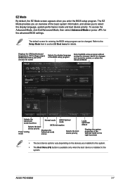
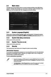
... setup program without saving the changes, saves the changes and resets the system, or enters the Advanced Mode Selects the Advanced mode functions Normal mode ASUS Optimal mode Selects the boot SATA information device priority Displays the Power saving Advanced mode mode menus Selects the boot device priority Loads optimized default... BIOS setup program. EZ Mode By default, the EZ Mode screen appears when you to the Setup Mode item in section 2.8 Boot menu for details. ASUS PIO-B85M 2-7
... setup program without saving the changes, saves the changes and resets the system, or enters the Advanced Mode Selects the Advanced mode functions Normal mode ASUS Optimal mode Selects the boot SATA information device priority Displays the Power saving Advanced mode mode menus Selects the boot device priority Loads optimized default... BIOS setup program. EZ Mode By default, the EZ Mode screen appears when you to the Setup Mode item in section 2.8 Boot menu for details. ASUS PIO-B85M 2-7

User Guide
Page 39
..., Boot, Tool, and Exit) on the menu bar have done in BIOS. A configurable field is a brief description of the menu screen is highlighted when selected. ASUS PIO-B85M 2-9 To display the submenu, select the item and press . Configuration fields These fields show the values for that you last modified and saved in the...
..., Boot, Tool, and Exit) on the menu bar have done in BIOS. A configurable field is a brief description of the menu screen is highlighted when selected. ASUS PIO-B85M 2-9 To display the submenu, select the item and press . Configuration fields These fields show the values for that you last modified and saved in the...
User Guide
Page 41
... security settings. 2.4.1 System Language [English] Allows you have forgotten your BIOS password, erase the CMOS Real Time Clock (RTC) RAM to clear the BIOS password. ASUS PIO-B85M 2-11 Otherwise, you enter the administrator password for information on how to erase the RTC RAM. • The Administrator or User Password items on top...
... security settings. 2.4.1 System Language [English] Allows you have forgotten your BIOS password, erase the CMOS Real Time Clock (RTC) RAM to clear the BIOS password. ASUS PIO-B85M 2-11 Otherwise, you enter the administrator password for information on how to erase the RTC RAM. • The Administrator or User Password items on top...
User Guide
Page 43
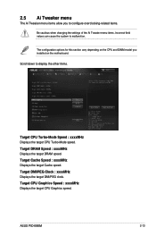
Target Cache Speed : xxxxMHz Displays the target Cache speed. ASUS PIO-B85M 2-13 Target CPU Graphics Speed : xxxxMHz Displays the target CPU Graphics speed. Target DMI/PEG Clock : xxxxMHz Displays the target DMI/PEG clock. Target DRAM ...
Target Cache Speed : xxxxMHz Displays the target Cache speed. ASUS PIO-B85M 2-13 Target CPU Graphics Speed : xxxxMHz Displays the target CPU Graphics speed. Target DMI/PEG Clock : xxxxMHz Displays the target DMI/PEG clock. Target DRAM ...
User Guide
Page 45
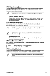
... item to configure a higher frequency for extra power support. Probe] Select to maintain the VRM thermal balance. [Extreme] Select to maintain the current VRM balance. ASUS PIO-B85M 2-15
... item to configure a higher frequency for extra power support. Probe] Select to maintain the VRM thermal balance. [Extreme] Select to maintain the current VRM balance. ASUS PIO-B85M 2-15

User Guide
Page 47
... the idle power-in Response [Auto] Allows you to improve power saving on the Fully Integrated Voltage Regulator as the processor enters low current mode. ASUS PIO-B85M 2-17 Configuration options: [Auto] [Disabled] [Enabled] Idle Power-in response. Use the and keys to adjust the value. 2.5.7 [Auto] [Disabled] [Enabled] CPU Spread Spectrum [Auto...
... the idle power-in Response [Auto] Allows you to improve power saving on the Fully Integrated Voltage Regulator as the processor enters low current mode. ASUS PIO-B85M 2-17 Configuration options: [Auto] [Disabled] [Enabled] Idle Power-in response. Use the and keys to adjust the value. 2.5.7 [Auto] [Disabled] [Enabled] CPU Spread Spectrum [Auto...


