
User Manual
Page 13
... with the list below. 1.2 Package contents Check your motherboard package for the following items. User Manual ASUS P8Z68 Deluxe motherboard User guide Support DVD 4 x Serial ATA 6.0 Gb/s cables 2 x Serial ATA 3.0 Gb/s cables 1 x ASUS SLI™ bridge connector 1 x ASUS Q-Shield 1 x ASUS front panel USB 3.0 box 1 x 2-in the long line of the above items is damaged or missing...
... with the list below. 1.2 Package contents Check your motherboard package for the following items. User Manual ASUS P8Z68 Deluxe motherboard User guide Support DVD 4 x Serial ATA 6.0 Gb/s cables 2 x Serial ATA 3.0 Gb/s cables 1 x ASUS SLI™ bridge connector 1 x ASUS Q-Shield 1 x ASUS front panel USB 3.0 box 1 x 2-in the long line of the above items is damaged or missing...
User Manual
Page 15
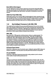
With iGPU on P8Z68 Deluxe motherboards, DIGI+ VRM intelligently adjust Vcore PWM, integrated graphics voltages and frequency modulation to a digital standard. DIGI+ VRM New ASUS DIGI+ VRM upgrades motherboard power delivery to minimize power loss through BIOS tuning and the ... reaches its full potential, adjusting frequencies dynamically and cutting EM interference by half to enhance system stability through enabled spread spectrum. ASUS P8Z68 Deluxe 1-3 New generation Dual Intelligent Processors 2 with DIGI+ VRM digital power design launch control into a new era, empowering users ...
With iGPU on P8Z68 Deluxe motherboards, DIGI+ VRM intelligently adjust Vcore PWM, integrated graphics voltages and frequency modulation to a digital standard. DIGI+ VRM New ASUS DIGI+ VRM upgrades motherboard power delivery to minimize power loss through BIOS tuning and the ... reaches its full potential, adjusting frequencies dynamically and cutting EM interference by half to enhance system stability through enabled spread spectrum. ASUS P8Z68 Deluxe 1-3 New generation Dual Intelligent Processors 2 with DIGI+ VRM digital power design launch control into a new era, empowering users ...
User Manual
Page 17
... beyond traditional keyboard-only BIOS controls to update the BIOS without the usual "fingers" - ASUS Q-Connector ASUS Q-Connector allows you to enable more environmentally-friendly. ASUS P8Z68 Deluxe 1-5 The exclusive EZ Mode displays frequently-accessed setup info, while the Advanced Mode is put...discrete graphics are needed, the graphics card is for the Intel® Sandy Bridge platform's powerful integrated graphics. ASUS Q-Design ASUS Q-Design enhances your motherboard against static electricity and shields it convenient and easy to the best available graphics resources ...
... beyond traditional keyboard-only BIOS controls to update the BIOS without the usual "fingers" - ASUS Q-Connector ASUS Q-Connector allows you to enable more environmentally-friendly. ASUS P8Z68 Deluxe 1-5 The exclusive EZ Mode displays frequently-accessed setup info, while the Advanced Mode is put...discrete graphics are needed, the graphics card is for the Intel® Sandy Bridge platform's powerful integrated graphics. ASUS Q-Design ASUS Q-Design enhances your motherboard against static electricity and shields it convenient and easy to the best available graphics resources ...

User Manual
Page 19
ASUS P8Z68 Deluxe 2-1 Chapter 2: Chapter 2 Hardware information 2.1 Before you proceed Take note of the following precautions before you install or remove any component, ensure that came with the ...
ASUS P8Z68 Deluxe 2-1 Chapter 2: Chapter 2 Hardware information 2.1 Before you proceed Take note of the following precautions before you install or remove any component, ensure that came with the ...

User Manual
Page 23
A DDR3 module is notched differently from a DDR or DDR2 module. Recommended memory configurations Chapter 2 ASUS P8Z68 Deluxe 2-5 DO NOT install a DDR or DDR2 memory module to the DDR3 slot. 2.2.3 System memory The motherboard comes with four Double Data Rate 3 (DDR3) Dual Inline Memory Modules (DIMM) slots.
A DDR3 module is notched differently from a DDR or DDR2 module. Recommended memory configurations Chapter 2 ASUS P8Z68 Deluxe 2-5 DO NOT install a DDR or DDR2 memory module to the DDR3 slot. 2.2.3 System memory The motherboard comes with four Double Data Rate 3 (DDR3) Dual Inline Memory Modules (DIMM) slots.
User Manual
Page 25
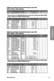
... • • 9-9-9-28 1.65 • • 9 1.65 • • • 9-11-9-27 1.66 • • • P8Z68 Deluxe Motherboard Qualified Vendors Lists (QVL) DDR3 1866(O.C.) MHz capability Vendor Part No. G.SKILL F3-16000CL9T-6GBPS(XMP) 6GB(3 x 2GB) DS - - G.SKILL F3-...• • • 1.65 • • • 1.65 • • 1.65 • • • 1.65 • • ASUS P8Z68 Deluxe 2-7 G.SKILL F3-16000CL6Q-8GBPIS(XMP) 8GB ( 4x 2GB ) SS - - Size SS/ Chip DS Brand CORSAIR CMT6GX3M3A1866C9(XMP) 6GB ( 3x 2GB ) DS - G....
... • • 9-9-9-28 1.65 • • 9 1.65 • • • 9-11-9-27 1.66 • • • P8Z68 Deluxe Motherboard Qualified Vendors Lists (QVL) DDR3 1866(O.C.) MHz capability Vendor Part No. G.SKILL F3-16000CL9T-6GBPS(XMP) 6GB(3 x 2GB) DS - - G.SKILL F3-...• • • 1.65 • • • 1.65 • • 1.65 • • • 1.65 • • ASUS P8Z68 Deluxe 2-7 G.SKILL F3-16000CL6Q-8GBPIS(XMP) 8GB ( 4x 2GB ) SS - - Size SS/ Chip DS Brand CORSAIR CMT6GX3M3A1866C9(XMP) 6GB ( 3x 2GB ) DS - G....

User Manual
Page 31
...) VGA configuration Single VGA/PCIe card Dual VGA/PCIe card PCI Express operating mode PCIe 2.0 x16_1 x16 (Recommend for single VGA) x8 PCIe 2.0 x16_2 N/A x8 ASUS P8Z68 Deluxe 2-13 Failure to unplug the power cord before adding or removing expansion cards. 2.2.4 Expansion slots Ensure to do so may cause you physical injury and...
...) VGA configuration Single VGA/PCIe card Dual VGA/PCIe card PCI Express operating mode PCIe 2.0 x16_1 x16 (Recommend for single VGA) x8 PCIe 2.0 x16_2 N/A x8 ASUS P8Z68 Deluxe 2-13 Failure to unplug the power cord before adding or removing expansion cards. 2.2.4 Expansion slots Ensure to do so may cause you physical injury and...

User Manual
Page 33
... you to power up or wake up when the system is ideal for overclockers and gamers who continually change settings to enhance system performance. 1. Chapter 2 ASUS P8Z68 Deluxe 2-15 The illustration below shows the location of the onboard power-on switch that you should shut down the system and unplug the power cable...
... you to power up or wake up when the system is ideal for overclockers and gamers who continually change settings to enhance system performance. 1. Chapter 2 ASUS P8Z68 Deluxe 2-15 The illustration below shows the location of the onboard power-on switch that you should shut down the system and unplug the power cable...

User Manual
Page 35
Refer to section 2.2.6 Onboard LEDs for fast, yet stable clock speeds. Chapter 2 4. ASUS P8Z68 Deluxe 2-17 However, the system will be activated after the next system bootup. • You may use the last setting you have made. TPU switch Turning ...
Refer to section 2.2.6 Onboard LEDs for fast, yet stable clock speeds. Chapter 2 4. ASUS P8Z68 Deluxe 2-17 However, the system will be activated after the next system bootup. • You may use the last setting you have made. TPU switch Turning ...

User Manual
Page 37
This user-friendly design provides an intuitional way to the motherboard design. 2.2.6 Onboard LEDs 1. ID LEDs The ID LEDs provide an elegant embellishment to locate the root problem within a second. 2. If an error is found , the LED next to the error device will continue lighting until the problem is solved. Chapter 2 ASUS P8Z68 Deluxe 2-19 POST State LEDs The POST State LEDs of CPU, DRAM, VGA card, and HDD indicate key components status during POST (Power-on Self Test).
This user-friendly design provides an intuitional way to the motherboard design. 2.2.6 Onboard LEDs 1. ID LEDs The ID LEDs provide an elegant embellishment to locate the root problem within a second. 2. If an error is found , the LED next to the error device will continue lighting until the problem is solved. Chapter 2 ASUS P8Z68 Deluxe 2-19 POST State LEDs The POST State LEDs of CPU, DRAM, VGA card, and HDD indicate key components status during POST (Power-on Self Test).
User Manual
Page 39
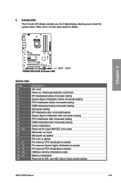
... - 2F 30 Description Not used Power on. 5. Q-Code LEDs The Q-Code LED design provides you the 2-digit display, allowing you to the Q-Code table below ) ASUS P8Z68 Deluxe 2-21 Refer to know the system status.
... - 2F 30 Description Not used Power on. 5. Q-Code LEDs The Q-Code LED design provides you the 2-digit display, allowing you to the Q-Code table below ) ASUS P8Z68 Deluxe 2-21 Refer to know the system status.

User Manual
Page 41
... started SCSI Reset SCSI Detect SCSI Enable Setup Verifying Password Start of Setup Reserved for ASL (see ASL Status Codes section below) Setup Input Wait ASUS P8Z68 Deluxe 2-23
... started SCSI Reset SCSI Detect SCSI Enable Setup Verifying Password Start of Setup Reserved for ASL (see ASL Status Codes section below) Setup Input Wait ASUS P8Z68 Deluxe 2-23

User Manual
Page 43
... is available only if you can create a RAID 0, 1, 5, and 10 configuration with the Intel® Rapid Storage Technology through the onboard Intel® Z68 chipset. ASUS P8Z68 Deluxe 2-25
... is available only if you can create a RAID 0, 1, 5, and 10 configuration with the Intel® Rapid Storage Technology through the onboard Intel® Z68 chipset. ASUS P8Z68 Deluxe 2-25
User Manual
Page 45
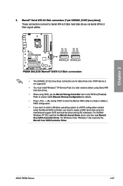
... driver disk using the Marvell SATA controller, you have to [Enabled]. For Windows Vista / Windows 7 OS, load only the Marvell 91xx SATA Controller Driver. Chapter 2 3. ASUS P8Z68 Deluxe 2-27 Refer to section 3.5.6 Onboard Devices Configuration for data drives only. For 32/64bit Windows XP OS, load first the Marvell shared library driver, and...
... driver disk using the Marvell SATA controller, you have to [Enabled]. For Windows Vista / Windows 7 OS, load only the Marvell 91xx SATA Controller Driver. Chapter 2 3. ASUS P8Z68 Deluxe 2-27 Refer to section 3.5.6 Onboard Devices Configuration for data drives only. For 32/64bit Windows XP OS, load first the Marvell shared library driver, and...

User Manual
Page 47
... to a slot opening at the back of the system chassis. Chapter 2 Never connect a USB cable to a slot opening at the back of the system chassis. ASUS P8Z68 Deluxe 2-29 Digital audio connector (4-1 pin SPDIF_OUT) This connector is for an additional Sony/Philips Digital Interface (S/PDIF) port(s). Connect the IEEE 1394a module cable to...
... to a slot opening at the back of the system chassis. Chapter 2 Never connect a USB cable to a slot opening at the back of the system chassis. ASUS P8Z68 Deluxe 2-29 Digital audio connector (4-1 pin SPDIF_OUT) This connector is for an additional Sony/Philips Digital Interface (S/PDIF) port(s). Connect the IEEE 1394a module cable to...

User Manual
Page 49
... in the BIOS setup to [HD]. 10. The power supply plugs are for a chassis-mounted front panel audio I /O module cable to [AC97]. Connect one orientation. ASUS P8Z68 Deluxe 2-31 Front panel audio connector (10-1 pin AAFP) This connector is set the item to this connector. • We recommend that supports either HD Audio...
... in the BIOS setup to [HD]. 10. The power supply plugs are for a chassis-mounted front panel audio I /O module cable to [AC97]. Connect one orientation. ASUS P8Z68 Deluxe 2-31 Front panel audio connector (10-1 pin AAFP) This connector is set the item to this connector. • We recommend that supports either HD Audio...

User Manual
Page 51
... on or puts the system in sleep mode. • Hard disk drive activity LED (2-pin IDE_LED) This 2-pin connector is for the system power button. ASUS P8Z68 Deluxe 2-33 Chapter 2 • System power LED (2-pin PLED) This 2-pin connector is for system reboot without turning off button (2-pin PWRSW) This connector is for...
... on or puts the system in sleep mode. • Hard disk drive activity LED (2-pin IDE_LED) This 2-pin connector is for the system power button. ASUS P8Z68 Deluxe 2-33 Chapter 2 • System power LED (2-pin PLED) This 2-pin connector is for system reboot without turning off button (2-pin PWRSW) This connector is for...

User Manual
Page 53
DO NOT install a LGA1156 CPU on the LGA1155 socket. 1 A B 2 3 ASUS P8Z68 Deluxe 2-35 Chapter 2 2.3.2 CPU installation The LGA1156 CPU is incompatible with the LGA1155 socket.
DO NOT install a LGA1156 CPU on the LGA1155 socket. 1 A B 2 3 ASUS P8Z68 Deluxe 2-35 Chapter 2 2.3.2 CPU installation The LGA1156 CPU is incompatible with the LGA1155 socket.

User Manual
Page 55
To install the CPU heatsink and fan assembly 1 A B 2 B A 3 4 ASUS P8Z68 Deluxe 2-37 Chapter 2 2.3.3 CPU heatsink and fan assembly installation Apply the Thermal Interface Material to the CPU heatsink and CPU before you install the heatsink and fan if necessary.
To install the CPU heatsink and fan assembly 1 A B 2 B A 3 4 ASUS P8Z68 Deluxe 2-37 Chapter 2 2.3.3 CPU heatsink and fan assembly installation Apply the Thermal Interface Material to the CPU heatsink and CPU before you install the heatsink and fan if necessary.

User Manual
Page 57
2.3.4 1 DIMM installation 2 Chapter 2 3 To remove a DIMM B A ASUS P8Z68 Deluxe 2-39
2.3.4 1 DIMM installation 2 Chapter 2 3 To remove a DIMM B A ASUS P8Z68 Deluxe 2-39


